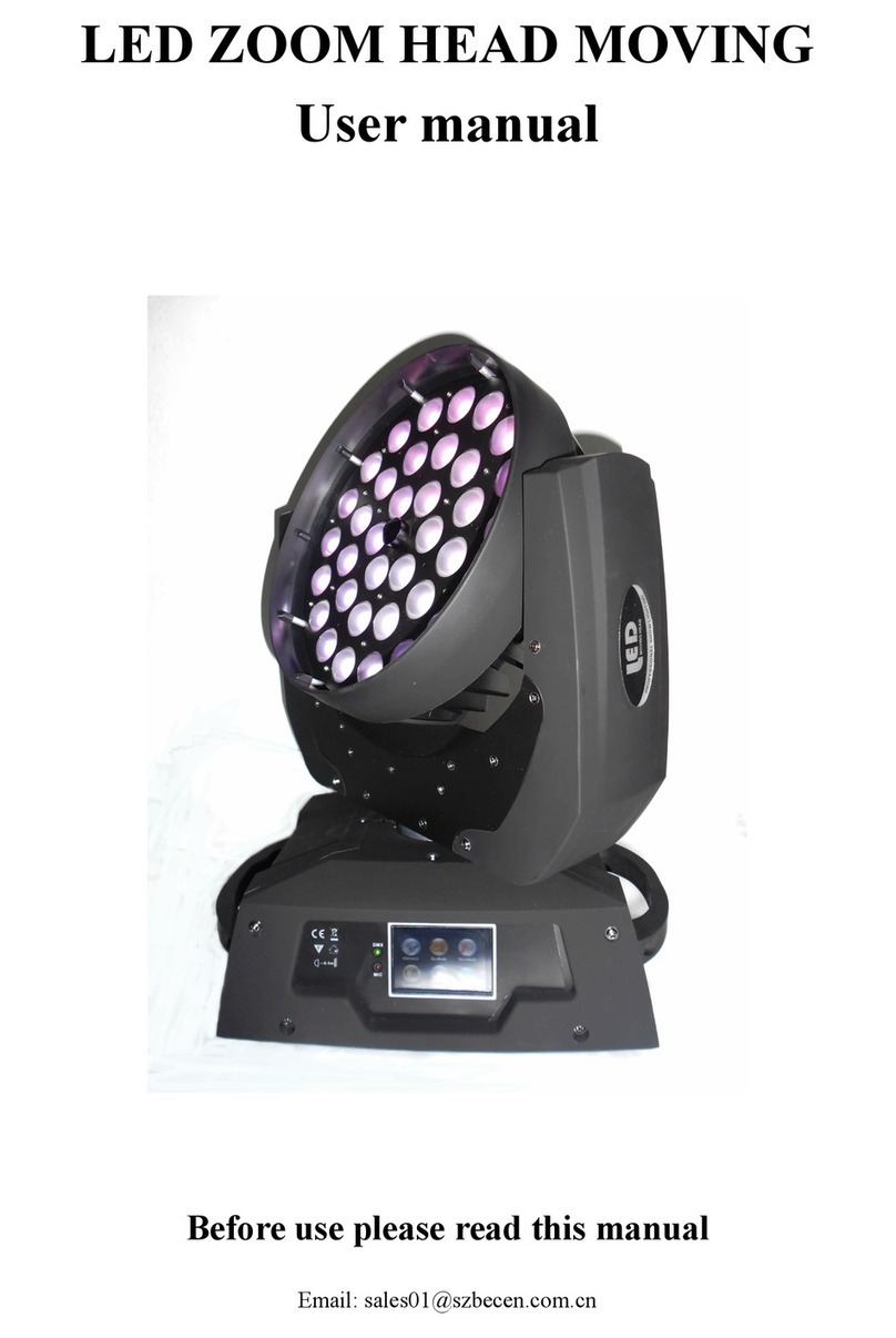
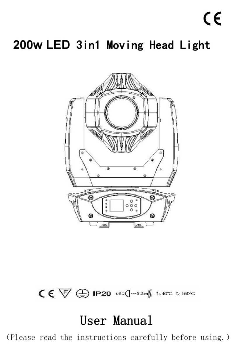
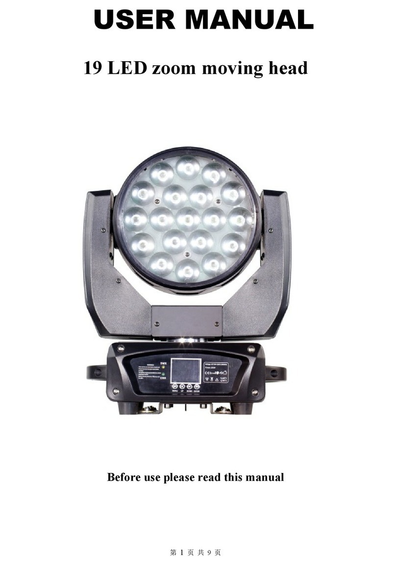
Becen BC-280A User manual

280W Beam moving head light
User manual

Catalog
Chapter 1 Consideratios and Instroll..........................................................................................1
1.1 Maintaining.......................................................................................................................1
1.2 Statement......................................................................................................................... 1
1.3 Products Notice...............................................................................................................1
1.4 Products intruducion.......................................................................................................1
1.5 Signal line connection(DMX)................................................................................... 2
1.6 Lamp installation............................................................................................................. 2
Chapter 2 Panel Operation.......................................................................................................... 4
2.1 Overview...........................................................................................................................4
2.2 Operation..........................................................................................................................4
2.2.1 Using intuitive touch or key to operate lamp..............................................................4
2.2.2 Parameter value input........................................................................................... 4
2.2.3 Setting parameter of Boolean value....................................................................5
2.2.4 Sub-page(Parameter)...................................................................................... 5
2.3 Function operate and parameter setting.....................................................................6
2.3.1 Address setting:setting DMX address code....................................................6
2.3.2 Operation mode:setting working mode of lamp............................................. 7
2.3.3 Display setting:Setting pannel display settting...............................................7
2.3.4 Test mode:Test mode.........................................................................................8
2.3.5Advanced setting:Setting working parameter of lamp................................... 9
2.3.6 State information:Checking current status of lamp..................................... 10
Chapter 3 Channel Description.................................................................................................11
3.1 Channel ........................................................................................................................ 11
3.1.1 Color channel(COLOR)................................................................................. 12
3.1.2 Gobo channel (GOBO)........................................................................................13
3.2 Channel chart Attension.............................................................................................. 14
Common malfunction and use attension ..................................................................................14
4.1 Common malfunction treatment................................................................................... 1
4.1.1 lamp not light up...................................................................................................14
4.1.2 beam function too dim.........................................................................................14
4.1.3 gobo function too blurred ..................................................................................14
4.1.4 Lamps work intermittently...................................................................................14
4.1.5 The lamp does not accept the control of the console after normal reset... 15
4.1.6 Lamps can not be started................................................................................... 15
4.2 Precautions for use...................................................................................................... 15

Page 1
Chapter 1 considerations and installation
1.1 Maintaining
his lamp shall be kept dry to avoid work in wet conditions.
Intermittent use will effectively extend the life of this lamp.
In order to get good ventilation effects and lighting effects, need to clean fans , fan nets
and lenses frequently. not use alcohol and other organic solvents to scrub the lamp shell to
avoid damage.
1.2 Statement
The performance is good and the packaging is complete when the product is in the
factory . All users shall strictly abide by the warning and operation stated above, any
damage caused by misuse is not within the warranty of our company, and the failures and
problems caused by neglect operation also are not the responsibility of dealers.
This manual is subject to technical change without prior notice.
No further notice if this manual has technical change.
1.3 Products consideration
ÿÿ In order to guarantee the life of product , pls do not put this in damp or leaking place,
further more ,can't work in the environment over 60 degrees temperature
ÿÿ Do not place this product where easy to loose or easy to vibrate.Do not place this
product where easy to loose or easy to vibrate.
ÿÿ In order to avoid the risk of electric shock, pls consult professional people for the
product maintenance.
ÿÿ Power source voltage change shouldn't over ±10%, voltage too high,will shorten the
life of bulb; too low,will affect the lighting effect of blub.
ÿÿ Need 20 minutes for lamp to cooled sufficiently when off the power ,then to reuse.
ÿÿ In order to guarantee the normal use of this product please read the instructions
carefully.
1.4 Products introduce
Bulb:Philips MSD Platinum 10R (life:2200 hour ,color temperature: 8000K);
Pan scanning:540°(16bit precision scanning) electronic error correction;
Tilt scanning:270° (16bit precision) electronic error correction ;
Color plate:1 color plate,14 color sheet per color plate;
Gobo wheel:1 Gobo wheel,17 Gobo
Effect wheel: bi-prism self-rotatione; effect moving,Atomization function;
0—100% machine dimming, support mechanical flash and adjustable speed flash
effect, support flash macro function
lens optics system,power-driven focus,beam angle 0-4 degree
Over-heat protection;
Voltage:100-240V,50/60HZ;
Power:400 W
IP protection rate:IP20;
Inductance ballast and AC/DC switch source

Page 2
1.5 signal line connection(DMX)
Use standard RS-485 cable:With screening, 120 ohm characteristic impedance, 22
and 24 AWG, low capacitive reactance.Don't use the microphone cable or cable with
different type characteristics .Terminal connection must use 3 or 5 needle type
male/female XLR connectors. Between Terminal plug terminal 2 and 3 must be inserted
into a 120 ohm impedance matching resistance (lowest 1/4 W).
Important tips: lines can not touch with each other or contact with metal shell.
Picture 1 DMX signal line connection sketch map
1.6 Lamp install
Lamps can be placed horizontally, hang on and hanging upside down. Always pay
attention to the installation when hang on and hanging upside down.
As shown in picture 2, before positing the lamps ,need to ensure the stability of the
installation place, when for the reverse hanging installation , ensure the lamp don't fell
from the brace ,
need to use safety rope through the brace and handle of lamp for insisting hanging to
make sure safety of prevent fall and slide of lamps.
In the installation and debugging,of the lamp, pedestrians are prohibited from passing
through, and regularly check if the safety ropes are worn or if the hook screws are
loose.
We are not liable for any consequences arising from the fall of the lamp due to the
unstable install.
Picture 2 lamp hang upside down sketch map

Page 3
Chapter 2 Panel operation
2.1 Overview
Lamp Panel sketch map as picture 3 showing, left side is TFT display,support touch
operation,right side is key,can operate lamp directly or setting system parameters.
Display and operation is similar to “Android cooperation system ” ,Click on the
corresponding item with your fingertips or blunt hard objects.
Notice:Do not use sharp objects to click on the display to avoid damage。
Picture 3 Display panel sketch map
2.2 Operation
2.2.1 Use intuitive touch or key to operate lamp
The left district is the TFT display and the touch district. Click on the panel contents
with the finger or the blunt objection to complete the operation of parameter setting or
status Viewing.
The right district is as for assist input function, if do not use TFT self-touch
function,can operate it by key.
2.2.2 Parameters value input
It will open the window like picture 4 showing when select parameter item need to
input some values.
Picture 4 Values setting page
Value setting :can be fastly setting the require values by pulling slider,also can be click
“up”or “down” key for precisely setting or use the keys on right side .

Page 4
Application value :when finish setting values by “up”or “down” key ,and press “apply”
application key in the bottom left corner, value will be sent to lamp immediately,but not be
save.
Save value: At any time,Click “confirm” key in the bottom right corner, current value will be
save to the internal storage, and this saved values will be applied to the lamp for the next
time starting up.
2.2.3 Setting Boolean parameter
When the setting parameter is a Boolean value (such as ON or OFF), you can directly click
the corresponding item to switch value, which will be saved to the internal storage. Press the
parameter option on the right, and the corresponding options will become gray. When the
hand is released, the corresponding parameters will change and save. If the parameter
option is not the parameter you want, you can move your finger to the rest of the screen, and
the corresponding parameters will not change.
The confirmation of important Boolean parameters will be set by the confirmation window,
as shown in picture 5 below:
Picture 5 confirm input window
2.2.4 Sub-page(parameter)
Click main menu to enter page of sub-menu,like picture 6 showing,total page is 6
page ,including different kinds of parameters and state like below:
Picture 6 page picture

Page 5
(ADDRESS):set up DMX address of lamp;
WORKMODE):Set up work-mode、master-slave mode of lamp;
DISPLAY:set up parameter of display interface,like language, screen-saver mode and so on.
TEST MODE:mainly use in test lamp, imitate the value of the corresponding DMX channel, and
corresponding functions of channel value can refer to channel function chart.
ADVANCED:set up operate parameter of lamp;
STATUS :Checking current status of lamp
2.3 Function operation and parameters setting
Enter setting interface ,like picture 6 showing
In main interface ,can enter setting interface of corresponding parameter by
touch/press 6 buttons
In setting interface of parameter,can press blue button in the left to quickly switch to
other setting interface.
2.3.1 Address setting : set up DMX address code
Click selection“address(ADDR)”,can enter setting page of DMX address code, address code value
range 1~512,address code can’t greater than (512-channel number )otherwise, lamp will be
uncontrollable, specific setting operation as below:
Enter DMX Settings interface, as shown in picture 7, click the white area on the right, It will pop-up
parameter Settings window as shown in picture 4 , you can directly pull the red diamond in the progress
bar to set up value of DMX address code , or press the "up" or "down" button to precisely setting DMX
address code you want , then press “Enter” key to save ,and to finish operation of address code setting.
Picture 7 address code setting page
2.3.2 operation mode:set up working mode of lamp
It is the page for set up operation mode 、bulb control and channel mode of lamp through picture 8
page , lamp support 3 operation mode(DMX mode、self-repelled and sound), detailed parameter value
setting pls refer to last chapter, specific parameter description as below:

Page 6
Picture 8 operation mode setting page
ÿÿDMX mode :lamp will receive data from console,and running according to this date.
ÿÿSelf-repelled :lamp do not receive data from console, and self -running with its internal fixed
program.
ÿÿSound:lamp do not receive data from console, when having stronger sound , lamp will operate 1
scene, ,otherwise will keep the last scene.
ÿÿMaster-salve selection:“Master-slave” selection only working in “self-repelled” or “sound” mode.
Closed--Internal program data of lamp operation will not sent to other lamp by DMX data line (default
setting)
Open--> data sending to other lamp in real time, other lamp(slave) will follow this lamp( master) operate
synchronously.
ÿÿ Bulb switch: can be control bulb’s open and close by this item setting.
Notice:Lamp can’t not switch more often which will shorten bulb’s life , bulb’s internal installation has set
up time interval is 30 minutes, so multiple open、close will be neglected,and will save the last time
operation.
ÿÿ Channel mode: lamp support 2 channel modes.
simplify--> 16 channel(default setting)
extend--> 20 channel
2.3.3 display setting:setting panel display setting
Lamp support Chinese-English bilingual, ,reversal lamp display,ect. enter parameter setting like
picture 9 for setting corresponding parameter.
Picture 9 display setting page
language(Language):select to display in Chinese or English ,immediate effect after
selection.
Screen-saver:will enter screen-saver status after 10 seconds of no any setting on lamp

Page 7
Close ---> no screen-saver, will display main interface all the time.
Mode1--> close the screen,Screen Blackout,saving mode.
Mode2--> display current DMX address code and operation mode.
Mode 3-->Display beam light icon and current operation mode (default setting)
Screen rotation: To select whether screen is display with 180 degree rotation, when lamp hang
upside down, this setting will make the content more clear.
Open---> normal display(default setting)
Close ---> 180 degree reversal display.
Touch switch :select “close”, touch function of display screen will be close, can used the encoder
knobs can only.
Open ---> touch function available (default setting)
Close ---> touch function unavailable, can use key or knob to operate only.。(choose)
Touch screen calibration:Click this item ,Entering the calibration page to re-calibrate the touch
accuracy of the touch screen. Normally, please do not enter this page.
2.3.4 Test mode: test lamp
Enter the page like picture 10, lamp will enter test mode,under this mode, lamp do
not receive DMX console data, parameters on the page is corresponding to value of DMX
channel, Can be change data s of corresponding parameter to control lamp cooperation.
图10 测试模式页面
X axis motor:Value(0~255);
Y axis motor:value(0~255);
Focus:value(0~255);
Color plate:value(0~255);
Gobo wheel:value (0~255);
Prism:value(0~255),prism will self -rotation at the same time after insert prism;
Fog Fihers:values(0~255);
Strobe:value(0~255);
2.3.5 Advanced setting: set up working parameter of lamp
Enter the page as shown in picture 11, adjusting actual parameter of the lamps for
conveniently actual installation

Page 8
Picture 11 Advanced setting page
X axis reverse-rotation:The initial position of X axis motor exchange with terminal position of X
axis, reverse-direction setting.
Close--> X axis motor is rotating in the forward direction(default setting)
Open--> X axis motor is rotating in the forward direction
Y axis:The initial position of Y axis motor exchange with terminal position of Y axis, ;
Close--> Y axis is rotating in the forward direction.(Default setting)
Open--> Y axis is rotating in the forward direction.
Optocoupler calibration:select whether to use optocoupler to automatically calibrate position of
X、Y
Open--> The lamp will automatically correct the position of the X or Y axis when the motor is offset
by the missing step. (default Setting)
Close--> The lamp will automatically correct the position of the X or Y axis when the motor is offset
by the missing step. (choose Settings)
X axis offset: setting the offset Angle of the initial position of the X axis motor, and the default value:
010.
Y axis offset:setting the offset Angle of the initial position of the Y axis motor, and the default value:
010.
Light mode:When setting up the power, the switch state of the bulb;
Set-up power light-up--> bulb will light when switch on.(default)
Hand-operated--> Need to hand-operated to light up the bulb after opening
Light up when reset --> blub Will light up after finish reset.
Data -hold:Setting the lamp’s position when turn off DMX signal(unplug console)
close--> lamp will return to the middle position when turn off the DMX signal (unplug console)
(Default setting)
Open--> Lamp will keep the current position state with turn off the DMX signal (unplug console)
Factory setting: Parameter of Initialize lamp
2.3.6 State information:checking lamp’s current status.
Enter page like picture 12 :
Picture 12 status information page

Page 9
Operation mode: Display current working mode of lamp.
Address code:Display current DMX address of lamp.
Software version:display current software version of lamp.
Set-up time:display total set-up time for this time.
Operation time:display total operated time of lamp.
Chapter 3 Channel Description
3.1 Channel chart
Channel chart of this lamp like chart 1 as below:
Channel
Name
Value
Description
CH1
X axis
0-255
0-540 degree
CH2
Y axis
0-255
0-270 degree
CH3
X axis fine
0-255
0-2 degree
CH4
Y axis fine
0-255
0-1 degree
CH5
XY speed
0-255
From fast to slow
CH6
Atomization
0-127
no
128-255
insert atomization
CH7
Strobe
0-3
Close optical shutter
4-103
From slow to fast pulse flash
104-107
Open optical shutter
108-207
From slow to fast gradual
flash
208-212
Open optical shutter
213-251
From slow to fast random
flash
252-255
Open optical shutter
CH8
dimmer
0-255
0-100% dimming
CH9
color
0-4
White light
5-9
White light + color 1
10-14
Color 1
15-19
Color 1 + color 2
20-24
Color 2
25-29
Color 2 + color 3
When<advanced setting -data hold>set to <open> ,DMX zero
clearing, can made the lamp return to mmidle position.
Make all motors reset of lamp.

Page 10
30-34
Color 3
35-39
Color 3 + color 4
40-44
Color 4
45-49
Color 4 + color 5
50-54
Color 5
55-59
Color 5 + color 6
60-64
Color 6
65-69
Color 6 + color 7
70-74
Color 7
75-79
Color 7 + color 8
80-84
Color 8
85-89
Color 8 + color 9
90-94
Color 9
95-99
Color 9 + Color 10
100-104
Color 10
105-109
Color 10 + Color 11
110-114
Color 11
115-119
Color 11 + Color12
120-124
Color 12
125-129
Color 12 + Color 13
130-134
Color 13
135-139
Color 13 + Color 14
140-199
from fast to slow forward
water-flow
200-255
from slow to fast reversal
water-flow
CH10
Gobo
0-4
White light
5-9
Gobo 1
10-14
Gobo 2
15-19
Gobo 3
20-24
Gobo 4
25-29
Gobo 5
30-34
Gobo 6
35-39
Gobo7
40-44
Gobo 8
45-49
Gobo 9
50-54
Gobo10
55-59
Gobo 11
60-64
Gobo12
65-69
Gobo 13
70-74
Gobo14
75-79
Gobo 15

Page 11
80-125
from fast to slow forward
water-flow
126-130
stop
131-180
from slow to fast reversal
water-flow
181-185
from slow to fast jitter Gobo
2
186-190
from slow to fast jitter Gobo
3
191-195
from slow to fast jitter Gobo
4
196-200
from slow to fast jitter Gobo
5
201-205
from slow to fast jitter Gobo
6
206-210
from slow to fast jitter Gobo
7
211-215
from slow to fast jitter Gobo
8
216-220
from slow to fast jitter Gobo
9
221-225
from slow to fast jitter Gobo
10
226-230
from slow to fast jitter Gobo
11
231-235
from slow to fast jitter Gobo
12
236-240
from slow to fast jitter Gobo
13
241-245
from slow to fast jitter Gobo
14
246-250
from slow to fast jitter Gobo
15
251-255
from slow to fast jitter Gobo
16
CH11
Prism 1
0-127
remove prism
128-255
insert prim 1
CH12
Prism
rotation
0-127
0-400 degree
128-187
from fast to slow forward
water-flow
188-195
stop
196-255
from slow to fast reverse
water-flow
CH13
Prism 2
0-127
remove prism

Page 12
128-255
insert prism 2
CH14
Prism 2
rotation
0-127
0-400 degree
128-187
from fast to slow forward
water-flow
188-195
stop
196-255
from slow to fast reverse
water-flow
CH15
focus
0-255
from far to near
CH16
reset
100-105
close bulb if over 3 sec.
200-205
open bulb if over 3 sec.
255
reset if over 3 sec.
CH17
reset
100-105
3 seconds lamp off
255
3 seconds lamp on
3 seconds reset
Chart 1 channel chart
Chapter 4 Common malfunction &use attention
4.1 Common malfunction treatment
The lamp have professional components such as microcomputer circuit
board and high voltage power supply. For your safety and product life,
non-professionals should not remove lamps and accessories without
authorization
.
4.1.1 bulb does not light
Possible reason:Bulb not totally cooling ,or bulb has reached life, treatment as following:
ÿÿ Due to improper operation, the bulb has not been completely cooling. Leave the lamp be cooled for
more than 10 minutes to made the bulb can fully recover to normal state, and then restart the power
supply.
ÿÿ Checking whether the bulb has reached the service life and should replace the new bulb;
ÿÿ Check whether the bulb and the lamp lighter are leaking, shedding or lose contact;
ÿÿ Replace the new lamplighter.
4.1.2 Beam look dim
Possible reason: use time of lamp is long or light path is not clean ,treatment as following:
ÿÿ Check whether the bulb has reached the service life and should replace the new bulb;
ÿÿ Checking whether optical part or bulb is clean and checking whether bulbs and other optical devices
have accumulated dust, and the lamps and components should be cleaned regularly.

Page 13
4.1.3 Gobo projection is fuzzy
ÿÿ Checking whether the electron focus channel value is suitable for the current range of the
projection.
4.1.4 The lamps work intermittently
Possible reasons: the internal circuit enters the protection state and treatment as following:
Checking whether the fan is working normally or dirty which made the internal temperature of the
lamp rise.
Checking whether the internal temperature control switch is closed;
Checking weather the bulb has reached the service life and should replace the new bulb.
4.1.5 Not accept console control after Lamp normally reset
Possible reason: the signal line malfunction or the lamp’s parameter setting is not normal, treatment as
following:
Checking the connection of the address code and the DMX signal line (whether the cord cable is in
good condition, and whether connection of Ka Nong head is loose);
Add signal amplifier, add120 ohm terminal resistor;
Checking the parameters of the lamp, make sure the lamps are in "DMX mode", and make sure that
the "CH20 operation mode" channel of DMX channel is located in the "DMX mode" data segment "0
~ 49".
4.1.6 Lamp can’t start
Possible reason: bad power circuit, treatment as following:
Checking whether the insurance of power input socket is fusing ,replace insurance.
Line Contact bad as vibration after lamp is in the long distance transportation.
Check the input power, computer board, etc service.
4.2 Precautions for use
Checking whether the local power supply is reach the requirements of rated voltage,
leakage protector、Load requirements of over-current protector for this products.
Do not use power lines with damaged insulation ,and power lines can not be
overlapped on the other wire;
Lamps USES is strong wind cooling,so accumulate dirt easily, must clean it once a
month, especially the cooling tuyere, otherwise,will be in a dust jam, which lead to
bad heat dissipation,and the lamps will be abnormal.
When install lamps, fixed screw must be tightened, and adds the safety rope, and
check regularly ;
When lamp is installing and positioning , any point on the surface of lamps keep the
minimum distance of 10 meters with anything easy to burn the explosive, and

Page 14
irradiation distance of 2.5 meters, please do not make the lamps directly install on the
surface of something combustible;
Using switching valve, closed time should be not more than 5 minutes, if you need to
close for a longer time ,pls use console( bulb control channel)to close bulb.
In order to ensure many sets of lamps follow scene effect better, lamps should not in
the unfinished scene all the time,while to start the next scene action,and it is better
not more than 3 minutes for this status to make sure many sets lamps can operate
synchronously.
In the process of use, such as lamps has abnormal condition, should stop using
lamps in time to prevent other malfunctions.
This manual suits for next models
1
Table of contents
Other Becen Dj Equipment manuals
