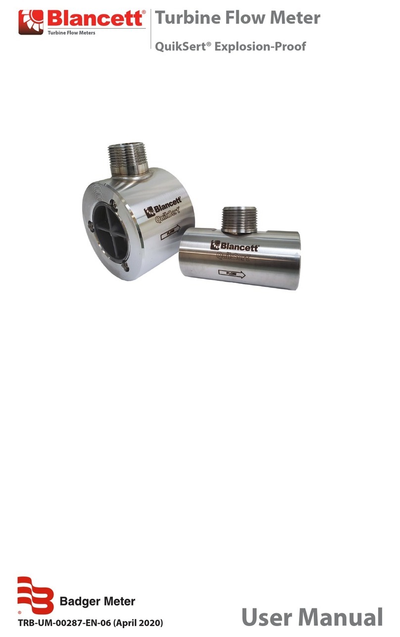
Blancett QUIKSERT User manual

QUIKSERT™FLOW METER
OPERATION & INSTALLATION
MANUAL
8635 Washington Ave.
Racine, Wisconsin 53406
Technical Toll-Free: 877.722.4631
Sales Toll-Free: 800.235.1638
Phone: 262.639.6770 Fax: 262.639.2267
www.blancett.com

2
TABLE OF CONTENTS
Introduction…..…………………..…………………..3
Specifications.………………………..…………….....4
Illustrations…...………….…………………………...5
Installation Instructions……………..…………….....6
Operational Startup…….……………………………9
Calibration…….……………………………………...9
Troubleshooting……………………………………...10
Part Numbering Information………………….……11
Repair Kit Information…….………………………..12
Statement of Warranty……………………………...13
Note: Blancett reserves the right to make any changes or
improvements to the product described in this manual at any
time without notice.

3
INTRODUCTION
The QuikSert™ turbine flow meter is designed with wear resis-
tant moving parts to provide trouble free operation and long ser-
vice life. The Quiksert™ Meter Repair Kit is designed for easy
field service of a damaged flow meter, rather than replacing the
entire flow meter (see Appendix C for repair kit information).
Repair parts are constructed of stainless steel alloy and tungsten
carbide.
Fluid moving through the turbine flow meter causes the rotor to
turn at a speed proportional to the flow rate. The rotor blade cuts
the magnetic field of the magnetic pick-up, which in turn gener-
ates a frequency output signal that is directly proportional to the
speed. The signal is used to represent flow rate and/or totaliza-
tion of fluid passing through the turbine flow meter and is always
expressed as the number of electric pulses that the meter produces
per US gallon. This value is constant over each flow meter’s
range and is unique to the meter.

4
SPECIFICATIONS
Temperature:
-150 ºF to 350 ºF (-101 ºC to 177 ºC)
Not to be used on temperatures below the freezing point of the liquid
Accuracy:
1% of reading
Repeatability:
0.1%
Pressure:
Varies based on class of ANSI flanges used for mounting. See table below
Meter Construction:
Internal Parts: Stainless Steel; Tungsten Carbide
Pulsation:
Severe pulsation will affect accuracy and shorten the life of the meter
Vibration and Shock:
Severe mechanical vibration may decrease service life of the meter
Filtration:
Install a strainer upstream of meter if small particles are present
Note: Pressure in excess of allowable rating may cause the
housing to burst and cause serious personal injury.
FLANGE RATING
(ANSI) 150# 300# 600# 900# 1500#
Working Pressure (psi) 285 740 1480 2220 3705
Working Pressure (Mpa) 1.97 5.10 10.20 15.31 25.55
*Test Pressure (psi) 427.5 1110 2220 3330 5557.5
*Test pressure (Mpa) 2.95 7.65 15.31 22.96 38.32
Note: Incompatible fluids will deteriorate internal parts, and
cause the meter to read inaccurately.

5
ILLUSTRATIONS
FIGURE 2 - Models B132-050
through B139-900
FIGURE 1 - Models B131-038
through B131-100

6
INSTALLATION INSTRUCTIONS
Before installation, the flow meter should be checked internally
for foreign material and to be sure that the rotor spins freely.
Fluid lines should also be cleared of all debris. The flow meter
must be installed with the flow indication arrow, etched on the
exterior of the meter body, pointing in the correct direction of
flow. The preferred mounting orientation is to have the meter
installed in horizontal piping, with the pick-up facing upward.
However, the meter will function in any position.
The liquid that is to be measured must be free from any large par-
ticles that may obstruct rotation of the rotor. If particles are pre-
sent, a mesh strainer should be installed upstream before opera-
tion of the flow meter (See Table 1).
TABLE 1
PART NUMBER STRAINER MESH CLEARANCE
B131-038 60 .0092
B131-050 60 .0092
B131-075 60 .0092
B131-088 60 .0092
B131-100 60 .0092
B132-050 60 .0092
B131-075 60 .0092
B132-088 60 .0092
B132-100 40 .0092
B132-150 20 .0340
B132-200 20 .0650
B133-300 10 .0900
B134-400 10 .0650
B136-600 4 .1875
B139-900 4 .0900
B138-800 4 .0900

7
The preferred plumbing setup is one containing a by-pass line
(Fig. 3) that allows meter inspection and repair without interrupt-
ing flow. If a by-pass line is not utilized, it is important that all
control valves be located down-stream of the flow meter (Fig. 4).
This is true with any restriction in the flow line that may cause
the liquid to flash. If necessary, air eliminators should be in-
stalled to ensure that the meter is no incorrectly measuring en-
trained air or gas.
It is recommended that a minimum length, equal to 10 (10) pipe
diameters of straight pipe, be installed on the up-stream side and
five (5) diameters on the down-stream side of the flow meter.
Otherwise meter accuracy may be affected. Piping should be the
same size as the flange size.
Do not locate the flow meter or connection cable close electronic
motors, transforming, sparking devices, high voltage lines, or
place connecting cable in conduit with wires furnishing power for
such devices. These devices can induce false signals in the flow
meter coil or cable, causing the meter to read inaccurately.
If problems arise with the flow meter and monitor consult Appen-
dix A (Trouble Shooting Guide). If further problems arise, con-
sult factory. Turbine Meter Repair Kits are also available, see
Appendix C. If the internal components of the turbine flow me-
ter are damaged beyond repair, these repair kits are available.
Information pertaining the turbine meter repair kits are referenced
in Appendix C.
Caution: Damage can be caused by striking an empty me-
ter with high velocity flow stream.

8
FIGURE 3 - Meter installation utilizing
a bypass line
FIGURE 4 - Meter installation without
utilizing a bypass line.

9
OPERATIONAL STARTUP
The following practices should be observed when installing and
starting the meter.
1. After meter installation, close the isolation valves, and open
the by-pass valve. Flow liquid through the by-pass valve for
sufficient time to eliminate any air or gas in the flow line.
2. Open up-stream isolating valve slowly to eliminate hydraulic
shock while charging the meter with the liquid. Open the
valve to full open.
3. Open down-stream isolating valve to permit meter to operate.
4. Close the bypass valve to a full position.
5. Adjust the downstream valve to provide the required flow rate
through the meter. Note: The downstream valve may be used
as a control valve.
CALIBRATION
The meter is calibrated on water at the factory and tagged with a
K-Factor (pulses per US Gallon). Also all attached electronics
have been calibrated to match the flow meter’s K-Factor. For
maximum accuracy, the meter should be calibrated with the ac-
tual fluid being measured. The QuikSert™ meter can be recali-
brated by any conventional meter proving processes used to cali-
brate standard meters.
Caution: High velocity air or gas may damage the internal
components of the meter.
Warning: Make sure that fluid flow has been shut off and
pressure in the line released before attempting to install
the meter in an existing system.

10
APPENDIX A
TROUBLE SHOOTING GUIDE
Trouble Remedy
Meter indicates
higher than actual
rate
• Increase back pressure
• Clean meter
• Clean meter
• Install gas eliminator ahead of meter
System works per-
fect, except indicates
lower flow over en-
tire range
Repair or replace bypass valves, or
faulty solenoid valves
Meter indicating high
flow, upstream pip-
ing at meter smaller
than meter bore
Change piping
Opposite effects of
above Change temperature, change fluid or
recalibrate meter
Possible Cause
• Cavitation
• Debris on rotor support
• Build up of foreign ma-
terial on meter bore
• Gas in liquid
Bypass flow, leak
Fluid jet impingement on
rotor
Viscosity lower than cali-
brated
Meter indicates lower
than actual flow rate
• Debris on rotor
• Worn bearing
• Viscosity higher than
calibrated
• Clean meter and add filter
• Recalibrate monitor
Erratic system indica-
tion, meter alone
works well (remote
monitor application
only)
Ground loop in shielding Ground shield one place only. Look
for internal electronic instrument
ground. Reroute cables away from
electrical noise
Indicator shows flow
when shut off
Mechanical vibration
causes rotor to oscillate
without turning
Isolate meter
Erratic indication at
low flow , good indi-
cation at high flow
Rotor has foreign material
wrapped around it Clean meter and add filter
No flow indication Faulty pick-up Replace pick-up
No flow indication.
Full or partial open
position
Fluid shock, full flow into
dry meter or impact
caused bearing separation
or broken rotor shaft
Rebuild meter with repair kit and re-
calibrate monitor. Move to loation
where monitor is full on start-up or add
downstream flow control valve

11
APPENDIX B
PART NUMBER INFORMATION

12
APPENDIX C
REPAIR KIT INFORMATION

13
STATEMENT OF WARRANTY
Blancett Flow Meters, Division of Racine Federated, Inc. warrants to
the end purchaser, for a period of one year from the date of shipment
from the factory, that all flow meters manufactured by it are free from
defects in materials and workmanship. This Warranty does not cover
products that have been damaged due to defects caused by abnormal
use, misapplication, abuse, lack of maintenance, modified or im-
proper installation. Blancett’s obligation under this warranty is lim-
ited to the repair of replacement of a defective product, at no charge
to the end purchase, if the product is inspected by Blancett and found
to be defective. Repair or replacement is at Blancett’s discretion. A
return goods authorization (RGA) number must be obtained from
Blancett before any product may be returned for warranty repair or
replacement. The product must be thoroughly cleaned and any proc-
ess chemicals removed before it will be accepted for return.
The purchaser must determine the applicability of the product for its
desired use and assumes all risks in connection therewith. Blancett
assumes no responsibility or liability for any omissions or errors in
connection with the use of its products. Blancett will under no cir-
cumstances be liable for any incidental, consequential, contingent or
special damages or loss to any person or property arising out of the
failure of any product, component or accessory.
All expressed or implied warranties, including the implied warranty
of merchantability and the implied warranty of fitness for a par-
ticular purpose or application are expressly disclaimed and shall
not apply to any products sold or services rendered by Blancett.
The above warranty supersedes and is in lieu of all other warranties,
either expressed or implied and all other obligations or liabilities. No
agent or representative has any authority to alter the terms of this war-
ranty in any way.

14
NOTES

15

16
8635 Washington Avenue • Racine, Wisconsin 53406
Technical Toll-Free: 877.722.4631
Sales Toll-Free: 800.235.1638
Phone: 262.639.6770 • Fax: 262.639.2267
www.blancett.com
Form: QuikSert Manual
Revision 03/06
Table of contents
Other Blancett Measuring Instrument manuals

Blancett
Blancett FloClean Service manual

Blancett
Blancett B2800 Standard User manual

Blancett
Blancett B2800 Standard User manual

Blancett
Blancett 1100 Series Service manual

Blancett
Blancett 900 Series User manual

Blancett
Blancett 1100 Series Service manual

Blancett
Blancett B1750 User manual

Blancett
Blancett QuikSert B131-038 User manual

Blancett
Blancett B1750 Service manual

Blancett
Blancett B2800 Standard User manual