Sigma Metalytics Precious Metal Verifier INVESTOR 3012 User manual

MANUAL
MODEL #3012

2
Contents
Caution......................................................................................................3
Device Diagram............................................................................................4
PMV Investor Functions...........................................................................5
How to Get the Most out of Your PMV.................................................6
Power On and Calibrate...........................................................................7
Setup...................................................................................................8
Metal Selection.............................................................................................9
Weight Entry...............................................................................................10
Measurement Screen..............................................................................12
Resistivity Testing....................................................................................14
Wand Use.....................................................................................................20
PC Interface.................................................................................................21
Investor Best Practices..........................................................................22
Common Questions..................................................................................24
Warranty....................................................................................................26

3
CAUTION
Read Before Use
The onboard sensor bridge is sensitive to
stress. DO NOT force it left or right, place
heavy objects on it, lift the device by the bridge.
Stress can cause miscalibration and damage.
make no claim, guarantee, or promise that measurements
any sample is or is not genuine. Measurement results, whether
within or without the bounds consistent with the selected
about or action taken with regard to any sample is entirely the
responsibility of the user. To ensure accuracy, thoroughly read
the included instructions and be aware of the special conditions
which may affect the readings.
4
Calibration
mm 10 50454035302505 2015 6055 80757065 100959085
s
a
m
p
l
e
m
u
s
t
c
o
v
e
r
i
n
n
e
r
c
i
r
c
l
e
[ █]
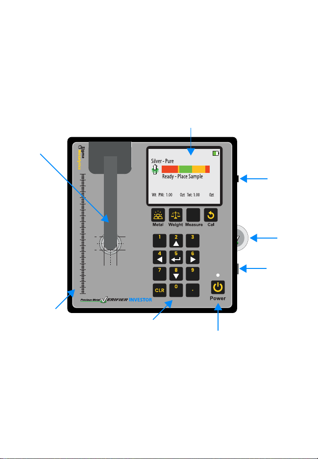
Device Diagram
Wand Port
Cal. Disk
USB C Port
Power Button
Keypad
Sizing Scale
Sensor Arm
Display
The arrow keys are used for
menu navigation and the
number keys are used for
weight entry.

5
PMV INVESTOR Functions
to determine if a coin or bar is consistent with genuine
precious metals.
The four measurements are:
1.
measure the sample’s resistivity just under the surface
of the metal. This ensures there are no contaminants or
foreign metals in or near the surface.
2.
sensor in the arm and in the base of the device to measure
the sample’s bulk resistivity. This measurement checks
the entirety of the sample and ensures there are no
contaminants or foreign metals anywhere between the two
sensors.
3.
electronically measures the thickness of the sample using
the average thickness of the face of the sample.
4.
density. The user must enter the measured weight of the
sample to perform this test.

6
How to get the most out of
your PMV INVESTOR
pass both resistivity and density testing. It’s important to
use the right settings and sensors to make sure your PMV
1. Power on the device and make sure it’s able to calibrate
Press the power button to turn the device on.
PMV calibrates itself while turning on, so be sure there
are no samples onboard. Read the Power On and Calibrate
section (Pg. 7) for more.
2.
Select the expected alloy of the sample and and enter the
weight. Follow the steps in the Metal Selection (Pg. 9)
and Weight Entry (Pg. 10) to do so. If you don’t know the
expected alloy or weight, refer to the Testing Best Practices
section (Pg. 20) for advice.
3. Perform
the resistivity testing by following the steps in the Resistivity
Testing section (Pg. 12). If possible, test the sample’s
(Pg. 14). Use the Results Interpretation section (Pg. 13) to
understand the results from the PMV.
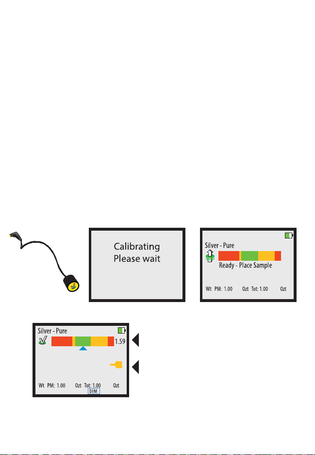
7
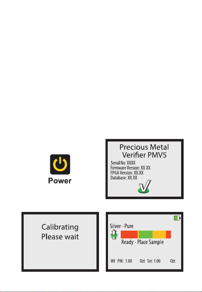
Power On and Calibrate
POWER button.
during the power on stage. While the device is powering on,
ensure there are no samples on the device and that the arm is
in the upright and resting position. This calibration checks the
internal components and prepares the device for use. When
complete, the device will show the READY screen.
8
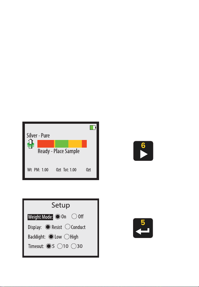
Setup
You may change some settings in the SETUP screen. To access
the SETUP screen, press the RIGHT button on the READY
screen. Use the UP and DOWN buttons to select the category,
and use the RIGHT and LEFT buttons to change the selection
within a category. Press the ENTER button when done to exit
the SETUP screen.
the settings are saved between uses.
9
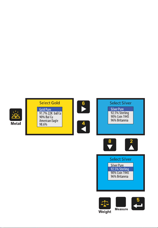
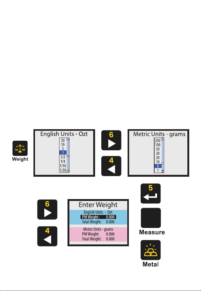
Metal Selection
Prior to taking a measurement, you must select the appropriate
metal or alloy from the metal selection database. Choose the
metal you expect the sample to be. Press the button to
open the selection menu. Use the LEFT and RIGHT buttons to
navigate between metal categories, and use the UP and DOWN
press the ENTER, , or WEIGHT
selection.
[ █]
10
Weight Entry
Press the WEIGHT button to enter the weight of a sample. You
can either select from the options listed in the English Units
(Ozt) and Metric Units (grams) categories, or you can manually
enter a weight on your own. Use the LEFT and RIGHT buttons to
navigate between categories, and use the UP and DOWN buttons
to select options within a category. When ready, press the
ENTER, , or
Entering the correct weight is important to accurately testing
dimensions.
[ █]
11
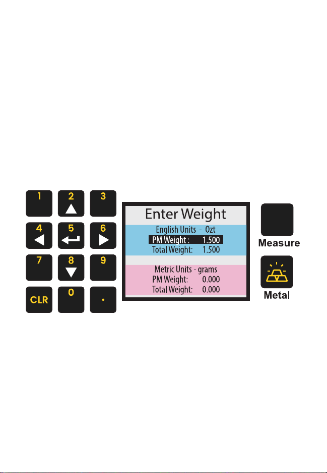
Manual Weight Entry
To manually enter weight, use the UP and DOWN buttons to
select the type of weight you want to enter. Press the ENTER
button to change the indicated weight. Use the buttons
to enter the desired weight. Press the WEIGHT button when
or button to continue use.
[ █]
PM Weight is the precious metal
weight in the sample.

12
Sample consistent with
selected metal
sample, like size, weight, and markings.
Sample inconsistent
with selected metal
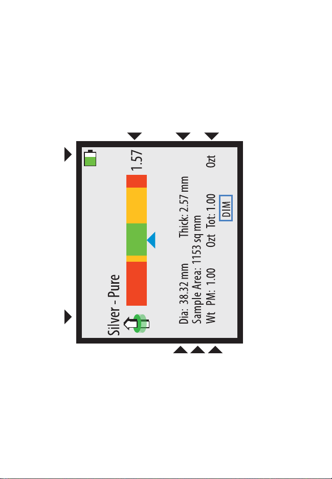
Measurement Screen
The screen will display when taking a reading.
Below is a basic explanation of each part of the screen. The
screen will not display the diameter, thickness, or weight if
weight mode is turned off. When using a Wand attachment, only
Blue Arrow
Indicates the device is getting a
reliable reading.
Red Arrow
Indicates the device is getting an unreliable
reading, treat result with caution.
Sideways Arrow
Indicates the result is off the
13
Calculated Diameter
Calculated Sample Area
Total Weight
Battery Indicator

14
Resistivity Testing
characteristic resistivity of precious metal coins and bars. Each
precious metal alloy has an expected resistivity value; the PMV’s
sensors test the sample’s resistivity and compare it to the known
resistivity of the selected alloy. To properly test your sample,
follow these steps:
1. Select the expected alloy of the
sample. Follow the steps in the Metal Selection (Pg. 9) to do
so. If you don’t know the expected alloy, refer to the Testing
Best Practices section (Pg. 20) for advice.
2. Place the sample on the
onboard sensor or touch the face of a Wand to the sample.
Refer to the Wand Use section (Pg. 18) for how to use a
wand.
Note: the sample does not need to physically touch the
sensor or wand. The PMV can read through plastic and
cardboard and can read through most cases. You do not
need to remove the sample from the case to test.
3. Refer to the Resistivity Testing
Interpretation section (Pg. 13) for details on determining
the results of your sample’s resistivity test. Generally, green
is good, yellow is caution, and red is questionable.
15
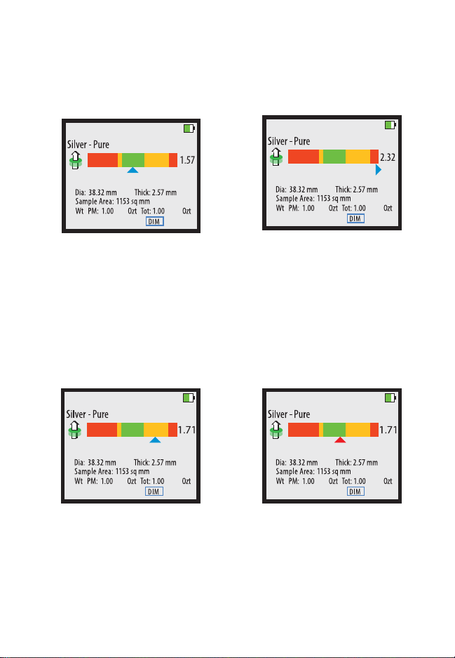
Results Interpretation
Reliable Reading,
Good Sample
The device is getting a
reliable reading and the
reading is consistent with the
selected metal.
Reliable Reading,
Questionable Sample
The device is getting a
reliable reading but the
sample is testing outside
of the expected range and
is inconsistent with the
selected alloy.
Reliable Reading,
The device is getting a
reliable reading but the
result is in the caution range.
sample. If it passes this is a
good sample.
Unreliable Reading
The arrow turns red when
the device is getting an
the testing conditions are
correct before trusting the
results.

16
Dimension Verification
To verify the dimensions of a sample, the correct metal must be
selected and the correct weight must be entered. To verify the
dimensions of a sample, press the button while the
device is reading the sample with the onboard sensor.
device will automatically select the mode that applies to the
using the Wand attachments.
17
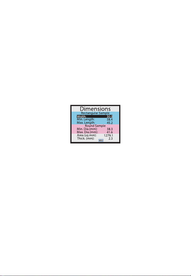
Numerical Dimension
Verification
To verify the dimensions of a sample, the correct metal must
be selected and the correct weight must be entered and the
sample must be tested using the onboard sensor. To verify the
dimensions of a sample, press the button while
the device’s onboard sensor is reading the sample. Once the
screen appears, you may move the sample away
from the sensor. The following will be displayed:
You may use the scale printed on the face of the device to
sample’s dimensions are within the dimensions calculated by
Measure the width of your sample.
Press the ENTER button and use the buttons to enter
the measured width. Press the WEIGHT
within the range. If it is not, then the sample is the wrong density.
Measure the diameter of your sample to
wrong density.

18
Visual Dimension Verification
Select the shape of the sample using the UP and DOWN buttons.
away from the sensor.
• align the right edge of the sample to
screen. The left edge of the sample is expected to fall within
the green range indicated on the screen. If the edge falls
within the range, then the sample’s density is consistent
with the selected metal. If the left edge falls outside of the
green range, then the sample’s density is inconsistent with
the selected metal.
• align the right edge of the
black line on the top edge of the screen. Use the UP and
DOWN buttons to adjust the indicated width on the screen
to match the width of the sample. While adjusting the width,
if the device determines that the sample is too long for the
mode. With the top edge, the right edge, and width aligned
properly, the sample’s left edge should fall somewhere
within the green range. If the edge falls within the range,
then the sample’s density is consistent with the selected
metal. If the left edge falls outside of the green range, then
the sample’s density is inconsistent with the selected metal.
If a sample fails the density test, double check to make sure
the correct weight is entered and the correct alloy is selected.
Then, test again before assessing the sample.

19
Round Sample
Visual Dimension Verification
Diagram
[ █]
Rectangular Sample
20
Wand Use
a Wand attachment, plug the Wand into the Wand Connector on
the device will self calibrate. Ensure the head of the Wand is
at least one inch away from any metal during this calibration
process. When the READY screen is displayed, you may touch
the face of the Wand to a sample.
When measuring with the Wand, only the
reading will display. There will also be a yellow Wand
indicator on the screen indicating the device is using the Wand’s
sensor. Wands are not able to perform density testing.
Wand Icon
Bullion
Wand Reading Screen
When the Wand is touched to metal, the screen
will change to show the results of the reading.
There is only one bar and a yellow icon appears
to indicate that the wand is in use.
Table of contents
Other Sigma Metalytics Measuring Instrument manuals


Popular Measuring Instrument manuals by other brands


PCB Piezotronics
PCB Piezotronics IMI SENSORS EX607A11 Installation and operating manual

Omron
Omron H7E manual

Fluidwell
Fluidwell F013-P user manual

Amprobe
Amprobe PRM-4 user manual

Powerbeat
Powerbeat POWERBEAT 1.0 user manual

Precision Digital Corporation
Precision Digital Corporation PD663 instruction manual