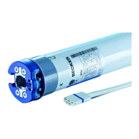
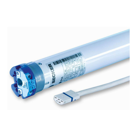
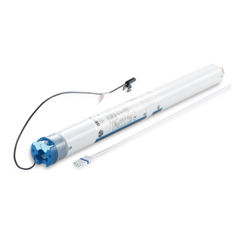
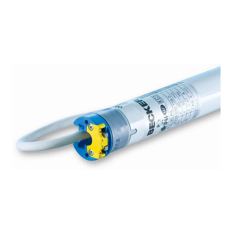
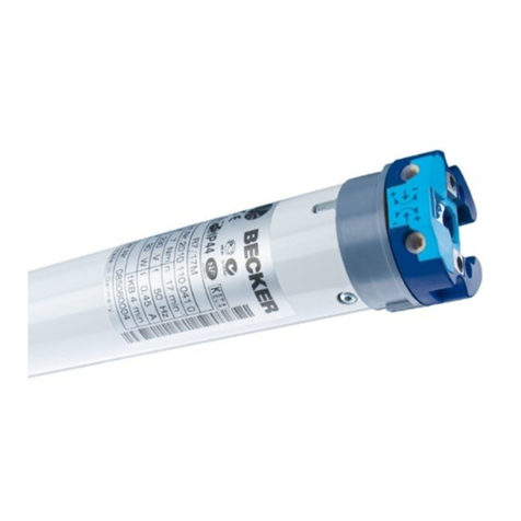
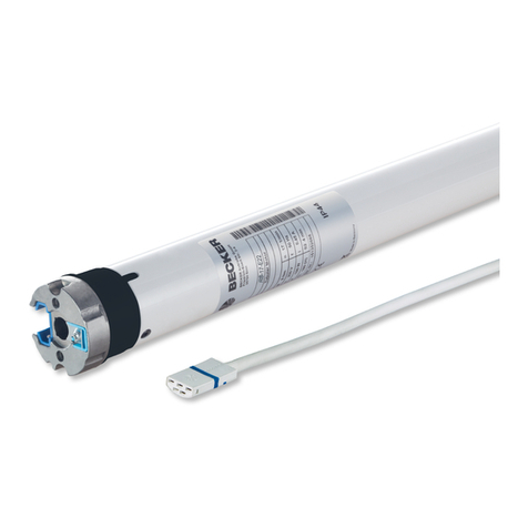
Becker R12/17HK User manual

DE
FR
GB
NL
Handleiding
Betriebsanleitung
Operating Instructions
Instructions d’utilisation
Rohrantriebe mit
Handkurbelbetätigung
Tubular Drives
With Hand Crank
Moteurs tubulaires
à commande de secours
Buismotoren met
noodhandbediening
R12/17HK -
R120/11HK
Wichtige Informationen für den Elektroanschluss
Important information about the electric supply
connection
Informations importantes pour le branchement
électrique
Belangrijke informaties voor de elektrische
aansluitingen

2
Inhaltsverzeichnis
Contents
Installation and Operating Instructions for R12/17HK to R120/11HK Tubular Drives with Hand Crank
Page
Introduction .............................................................................................................................................................................................................................................. 12
Warranty .................................................................................................................................................................................................................................................... 12
Safety Information.................................................................................................................................................................................................................................. 13
Intended Use ............................................................................................................................................................................................................................................. 13
Mounting Instructions........................................................................................................................................................................................................................... 14
Setting the End Limits ........................................................................................................................................................................................................................... 16
Using the Hand Crank ........................................................................................................................................................................................................................... 17
Information for the Electrician .......................................................................................................................................................................................................... 17
Technical Data .......................................................................................................................................................................................................................................... 18
Wiring Diagram ........................................................................................................................................................................................................................................ 18
zur Montage- und Betriebsanleitung der Rohrantriebe mit Handkurbelbetätigung R12/17HK bis R120/11HK
Seite
Einleitung ................................................................................................................................................................................................................................................... 4
Gewährleistung ........................................................................................................................................................................................................................................ 4
Sicherheitshinweise................................................................................................................................................................................................................................ 5
Bestimmungsgemäße Verwendung .................................................................................................................................................................................................. 6
Montageanleitung .................................................................................................................................................................................................................................. 6
Positionierung der Endlagen ............................................................................................................................................................................................................... 8
Einsatz der Handkurbel ......................................................................................................................................................................................................................... 9
Hinweise für den Elektro- und Rollladenfachmann.................................................................................................................................................................... 9
Technische Daten .................................................................................................................................................................................................................................... 10
Anschlussbeispiele .................................................................................................................................................................................................................................. 10

3
DE
GB
FR
NL
Sommaire
Inhoudsopgave
bij de montage- en gebruiksaanwijzing voor de Buismotoren met noodhandbediening R12/17HK tot R120/11HK
Pagina
Inleiding ...................................................................................................................................................................................................................................................... 28
Garantiegegevens.................................................................................................................................................................................................................................... 28
Veiligheidsrichtlijnen ............................................................................................................................................................................................................................. 29
Doelmatig gebruik ................................................................................................................................................................................................................................... 29
Montage-instructies .............................................................................................................................................................................................................................. 30
Positionering van de eindposities...................................................................................................................................................................................................... 32
Gebruik van de handkruk...................................................................................................................................................................................................................... 33
Aanwijzingen voor de elektricien en de rolluikmonteur ........................................................................................................................................................... 33
Technische gegevens .............................................................................................................................................................................................................................. 34
Aansluitvoorbeelden............................................................................................................................................................................................................................... 34
des instructions de montage et d'utilisation des moteurs tubulaires à commande de secours R12/17HK à R120/11HK
Page
Introduction .............................................................................................................................................................................................................................................. 20
Prestation de Garantie .......................................................................................................................................................................................................................... 20
Instructions de sécurité ........................................................................................................................................................................................................................ 21
Utilisation conforme aux prescriptions ........................................................................................................................................................................................... 21
Instructions de montage ...................................................................................................................................................................................................................... 22
Réglage des positions finales .............................................................................................................................................................................................................. 24
Utilisation de la manivelle ................................................................................................................................................................................................................... 25
Informations pour l’électricien et le spécialiste en volets roulants ...................................................................................................................................... 25
Caractéristiques techniques ................................................................................................................................................................................................................ 26
Exemples de raccordement .................................................................................................................................................................................................................. 26

4
Betriebsanleitung
Inhaltsverzeichnis
Einleitung
zur Montage- und Betriebsanleitung der Rohrantriebe mit Handkurbelbetätigung R12/17HK bis R120/11HK
Seite
Einleitung ................................................................................................................................................................................................................................................... 4
Gewährleistung ........................................................................................................................................................................................................................................ 4
Sicherheitshinweise................................................................................................................................................................................................................................ 5
Bestimmungsgemäße Verwendung .................................................................................................................................................................................................. 6
Montageanleitung .................................................................................................................................................................................................................................. 6
Positionierung der Endlagen ............................................................................................................................................................................................................... 8
Einsatz der Handkurbel ......................................................................................................................................................................................................................... 9
Hinweise für den Elektro- und Rollladenfachmann.................................................................................................................................................................... 9
Technische Daten .................................................................................................................................................................................................................................... 10
Anschlussbeispiele .................................................................................................................................................................................................................................. 10
Vielen Dank für den Kauf dieses BECKER Produktes
Die Rohrantriebe mit Handkurbelbetätigung R12/17HK bis R120/11HK sind hochwertige Qualitätsprodukte mit vielen Leistungsmerkmalen:
• Für den Einsatz im Rollladenbereich
• Für den Einsatz im Sonnenschutzbereich
• Für den Einsatz im Torbereich
• Leichte Endschaltereinstellung am Antrieb
• Kompatibel mit allen BECKER-Steuerungen für Rollladen- und Sonnenschutzanwendungen
Beachten Sie bitte bei der Installation sowie bei der Einstellung des Gerätes die vorliegende Betriebsanleitung.
Gewährleistung
BECKER-Antriebe GmbH ist von der gesetzlichen und vertraglichen Gewährleistung für Sachmängel und Produkthaftung befreit, wenn ohne
unsere vorherige Zustimmung eigene bauliche Veränderungen und/oder unsachgemäße Installationen gegen unsere vorgegebenen Montage-
richtlinien vorgenommen, ausgeführt oder veranlasst werden.
Der Weiterverarbeiter hat darauf zu achten, dass alle für die Herstellung und Kundenberatung erforderlichen gesetzlichen und behördlichen
Vorschriften, insbesondere die EMV-Vorschriften, eingehalten werden.
Das vorliegende Produkt unterliegt technischen Weiterentwicklungen und Verbesserungen, informieren Sie sich in den aktuellen Verkaufsunter-
lagen über die genaue Produktspezifikationen.
Trotz umfangreicher Tests kann die Funktion der Antriebe in Verbindung mit Fremdsteuerungen nicht pauschal garantiert werden. Bitte wenden
Sie sich in solchen Fällen vor der Installation an uns, wir beraten Sie gerne.

5
Betriebsanleitung
DE
GB
FR
NL
Sicherheitshinweise
Die folgenden Sicherheitshinweise und Warnungen dienen zur Abwendung von Gefahren sowie zur Vermeidung von Personen- und Sachschäden.
Diese Anleitung aufbewahren.
Vorsicht
Achtung
Hinweis
Wichtige Sicherheitshinweise für den Benutzer.
Vorsicht! Nichtbeachten kann zu ernsthaften Verletzungen führen.
• Arbeiten, einschließlich Wartungsarbeiten, an der Elektroinstallation dürfen nur von autorisiertem Elektro-Fachpersonal
durchgeführt werden.
• Erlauben Sie Kindern nicht, mit Steuerungen zu spielen.
• Überprüfen Sie die Rollladen- oder Sonnenschutzanlage regelmäßig auf Verschleiß und Beschädigungen.
• Beschädigte Anlagen unbedingt bis zur Instandsetzung stilllegen.
• Rollladen- oder Sonnenschutzanlagen nicht betreiben, wenn sich Personen oder Gegenstände im Gefahrenbereich befin-
den.
• Gefahrenbereich der Rollladen- oder Sonnenschutzanlage während des Betriebs beobachten.
• Rollladen- oder Sonnenschutzanlage stillsetzen und vom Versorgungsnetz trennen, soweit dies durch Lösen einer Steck-
verbindung möglich ist, wenn Wartungs- und Reinigungsarbeiten entweder an der Anlage selbst oder in deren unmittel-
barer Nähe durchgeführt werden.
• Ausreichend Abstand (mindestens 40cm) zwischen bewegten Teilen und benachbarten Gegenständen sicherstellen.
• Quetsch- und Scherstellen sind zu vermeiden oder zu sichern.
Wichtige Sicherheitshinweise für den Monteur.
Vorsicht! Nichtbeachten kann zu ernsthaften Verletzungen führen.
Sicherheitshinweise der EN 60 335-2-97:2000 beachten
• Arbeiten an der Elektro-Installation dürfen nur von qualifiziertem Fachpersonal durchgeführt werden.
• Beim Betrieb elektrischer oder elektronischer Anlagen und Geräte stehen bestimmte Bauteile unter gefährlicher elektri-
scher Spannung. Bei unqualifiziertem Eingreifen oder Nichtbeachtung der Warnhinweise können Körperverletzungen
oder Sachschäden entstehen.
• Alle geltenden Normen und Vorschriften für die Elektroinstallation sind zu befolgen.
• Es dürfen nur Ersatzteile, Werkzeuge und Zusatzeinrichtungen verwendet werden, die von der Firma BECKER freigegeben
sind.
• Für nicht freigegebene Fremdprodukte oder Veränderungen am Zubehör haftet der Hersteller oder Anbieter nicht für
entstandene Personen- oder Sachschäden sowie Folgeschäden.
• Alle zum Betrieb nicht zwingend erforderlichen Leitungen und Steuereinrichtungen vor der Installation außer Betrieb
setzen.
• Steuereinrichtungen in Sichtweite des angetriebenen Produktes in einer Höhe von über 1,5m anbringen.
• Ausreichend Abstand (mindestens 40cm) zwischen bewegten Teilen und benachbarten Gegenständen sicherstellen.
• Nennmoment und Einschaltdauer müssen auf die Anforderungen des angetriebenen Produkts abgestimmt sein.
• Technische Daten - Nennmoment und Betriebsdauer finden Sie auf dem Typenschild des Rohrantriebs.
• Bewegende Teile von Antrieben die unter einer Höhe von 2,5 m vom Boden oder einer anderen Ebene betrieben werden,
müssen geschützt sein.
• Quetsch- und Scherstellen sind zu vermeiden oder zu sichern.
• Sicherheitsabstände gem. DIN EN 294 einhalten.
• Ergänzende Hinweise entnehmen Sie bitte auch den BECKER Produktinformationen.
• Bei Toranwendungen ist insbesondere die Norm EN 12453 zu beachten.
Bezeichnet eine mögliche gefährliche Situation. Wenn sie nicht gemieden wird, können Verletzun-
gen die Folge sein.
Bezeichnet eine mögliche gefährliche Situation. Wenn sie nicht gemieden wird, kann das Produkt
oder etwas in seiner Umgebung beschädigt werden.
Bezeichnet Anwendungstips und andere nützliche Informationen.

6
Betriebsanleitung
2
Montageanleitung
Montage des Rohrantriebes
Der Monteur muß sich vorher von der erforderlichen Festigkeit des Mauerwerks bzw. des
Rollladenkastens (Drehmoment des Antriebs plus Gewicht des Rollladens) überzeugen.
Vorsicht
Elektroanschlüsse dürfen nur von einer Elektrofachkraft durchgeführt
werden. Vor der Montage ist die Stromzuleitung spannungsfrei zu
schalten. Bitte geben Sie die beiliegenden Anschlußinformationen dem
ausführenden Elektroinstallateur.
1. Ermitteln Sie den seitlichen Platzbedarf (M) des Kopfstückes (Abb1.), des Gegen-
lagers und des Motorlagers, um die benötigte Länge der Wickelwelle zu errechnen.
Das lichte Maß des Rollladenkastens (X) minus der Gesamtlänge von Wandlager,
Kopfstück (M) und Gegenlager (G) ergibt die Länge (L) der Wickelwelle:
L=X-(G+M) (Abb. 2).
Messen Sie den Abstand von Wandlager und Anschlußkopf selbst aus, da diese je
nach Kombination von Motor und Lager variieren können.
2. Befestigen Sie dann Wand- und Gegenlager.
Achtung
Die Befestigungselemente (Wandhalterungen) müssen so ausgerichtet
und befestigt werden, dass beim Verschrauben des Handkurbel-Gehäu-
ses keine Verspannungen auftreten können.
Sofern Rollladen mit Hochschiebesicherungen zum Einsatz kommen, müssen Wand-
und Gegenlager dauerhaft fest mit der Wand verbunden und gegen Ausheben/
Hochschieben gesichert werden. Verwenden Sie dafür nur geeignete Lager und Pan-
zer.
Bitte beachten Sie bei der Montage des Antriebes folgende Punkte:
• Montage des Mitnehmers mit Mitnehmersicherung bei den Antrieben
R12/17HK bis R25/17HK:
Die Einschubrichtung der Mitnehmersicherung ist durch seine Form vorgegeben. Bei
Einschieben der Mitnehmersicherung achten Sie auf das Einrasten der Rastnase.
Dies ist durch ein Klicken hörbar. Überprüfen Sie den festen Sitz der Sicherung durch
Ziehen am Mitnehmer (Abb. 3).
• Montage des Mitnehmers mit Schraubverbindung bei den Antrieben
R30/17HK bis R120/11HK:
Hier erfolgt die Befestigung mit einer Schraube M6x12. Diese wird mit einer Unter-
legscheibe M6 und einer entsprechenden Zahnscheibe gesichert (Abb. 3).
1
M
ML
X
G
3
Rastbohrung
Rastnase
Mitnehmersicherung
R12/17HK bis R25/17HK
Mitnehmer
Schraube M6x12
Unterlegscheibe
Zahnscheibe
R30/17HK bis R120/11HK
Mitnehmer
Bestimmungsgemäße Verwendung
Die Rohrantriebe der Typen R12/17HK bis R120/11HK sind ausschließlich für den Betrieb von Rollladen, Rolltoren und Markisen bestimmt.
Die Handkurbel ist nur für die bequeme Handbedienung bei Stromausfall vorgesehen. Ein Dauerbetrieb oder Einsatz von Werkzeugen (z.B.
Bohrmaschinen zum Betätigen der Kurbel) ist verboten, da dies nach entsprechender Zeit zum Ausfall der Handfunktion und damit des Rohran-
triebes führt.
Eine andere oder eine darüber hinausgehende Benutzung gilt nicht als bestimmungsgemäß.
Werden die Antriebe für andere als die oben genannten Einsätze verwendet oder werden Veränderungen an den Geräten vorgenommen, die die
Sicherheit der Anlage beeinflussen, so haftet der Hersteller oder Anbieter nicht für entstandene Personen- oder Sachschäden sowie Folgeschä-
den.
Für den Betrieb der Anlage oder Instandsetzung sind die Angaben der Betriebsanleitung zu beachten. Bei unsachgemäßem Handeln haftet der
Hersteller oder Anbieter nicht für entstandene Personen- oder Sachschäden sowie Folgeschäden.

7
Betriebsanleitung
DE
GB
FR
NL
4
6
7,5mm
8,5mm
11mm
18mm
R12/17HK - R50/11HK
R44/14HK - R120/11HK
5
7
3. Vor dem Einbau in die Welle, das Maß vom Wellenende bis zur Mitte des Mitnehmers
abnehmen und auf der Welle anzeichnen (Abb. 4).
• Bei Profilwellen:
Toleranzen der Nutbreiten in verschiedenen Wickelwellen lassen sich bei einigen
Mitnehmern durch Drehen des Mitnehmers in eine andere Nutausnehmung ausglei-
chen. Diese Nutausnehmungen haben verschiedene Maße und ermöglichen Ihnen
einen paßgenauen Einbau des Antriebes (Abb. 5).
• Bei Rundwellen:
Klinken Sie vorher das Rohr auf der Motorseite aus, damit der Nocken des Laufringes
mit in die Welle geschoben werden kann. Der Nocken des Laufringes darf zur Welle
kein Spiel haben (Abb. 6).
4. Montieren Sie den Antrieb mit entsprechendem Laufring (A) und Mitnehmer (B).
Schieben Sie den Antrieb mit dem vormontierten Laufring und Mitnehmer form-
schlüssig in die Welle ein. Achten Sie auf guten Sitz des Laufringes und des Mitneh-
mers in der Welle (Abb. 7).
Verbinden Sie den Mitnehmer des Rohrantriebes grundsätzlich, wie folgt, mit der
Wickelwelle:
Achtung
Beim Anbohren der Wickelwelle nie im Bereich des Rohrantriebs boh-
ren! Der Antrieb darf beim Einschieben in die Wickelwelle nicht einge-
schlagen und nicht fallen gelassen werden! (Abb. 4 und 7)
Die Fa. BECKER empfiehlt, auch das Gegenlager mit der Wickelwelle zu verschrau-
ben.
5. Hängen Sie die montierte Baueinheit bestehend aus Welle, Rohrantrieb und Gegen-
lager, wie folgt, in den Rollladenkasten ein (Abb. 8).
1. Führen Sie zuerst den Lagerbolzen in das Gegenlager ein (1.).
2. Anschließend montieren Sie das Handkurbel-Gehäuse mit mindestens 2 Schrau-
ben M6 an das jeweilige Befestigungselement (2.).
3. Fixieren Sie nun das Gegenlager
Achtung
Bei der Verwendung von Hochschiebesicherungen müssen geschlossene
Lagerstellen eingesetzt werden. Der Rohrantrieb drückt den Panzer bei
geschlossenem Rollladen nach unten, um ein Untergreifen bzw. Hoch-
schieben zu verhindern. Verwenden Sie nur ausreichend stabile Panzer,
beispielsweise aus Aluminium, Stahl oder Holz. Um eine Beschädigung
des Panzers zu vermeiden, muß der Panzer auf ganzer Höhe in Führungs-
schienen laufen.
6. Sichern Sie den Antrieb entsprechend der Befestigungsart des Wandlagers mit Splint
oder Federstecker. Die Inbetriebnahme kann mit der BECKER-Schaltergarnitur (Art.-
Nr. 4901 002 181 0) oder dem vorgesehenen Bedienelement erfolgen.
Achtung
Die Schaltergarnitur ist nicht für die dauerhafte Bedienung geeignet,
sondern nur für die Inbetriebnahme vorgesehen!
7. Verbinden Sie die Anschlußlitzen des Rohrantriebs farbengleich mit denen der
Schaltergarnitur bzw. des Bedienelements und schalten Sie die Netzspannung ein
(Abb. 9).
A
B
C
B
8
1.2.
AB
9
-sbeirtnA
]mm[eßörg
Ø-nellewlekciW
]mm[
tnemomherD
]mN[.xam
nebuarhcssgnugitsefeB
).kctS4(remhentiM
54Ø -ffotstsnuKmm07-06
remhentiM-ßugkcurDredo 05 ebuarhcshcelB-kneS
2897NID01x3,6TS
85Ø mm021-36
remhentiM-ßugkcurD 021 ebuarhcshcelB-kneS
2897NID01x5,9TS
85Ø mm331-58
remhentiM-ulA 021 nebuarhcskneS
1997NID61x8M

8
Betriebsanleitung
10
Hinweis
Achten Sie bei der Montage des Rollladens und der Markise immer darauf, daß das Motoranschlußkabel nicht bei Betrieb der
Anlage beschädigt werden kann.
Decken Sie scharfe Kanten, über die das Kabel geführt wird, mit entsprechendem Schutzband ab. Bei eventuellen Beschädi-
gungen der Netzanschlußleitung darf ein Austausch dieser nur durch den Hersteller erfolgen. Verlegen Sie das Kabel zum
Motor hin ansteigend, bzw. bilden Sie mit dem Kabel eine Schlaufe, damit Regen am unteren Punkt ablaufen kann.
Einstellung der oberen Endlage
Betätigen Sie den Schalter für die AUF-Richtung. Der Antrieb läuft aufwärts und rollt den Rollladen bzw. den Behang auf. Erweitern oder
vermindern Sie den Abschaltpunkt durch Drehen der entsprechenden Einstellschraube.
Hinweis
Die Länge des Rollladenpanzers darf die Fensterhöhe plus die lichte Höhe des Rollladenkastens nicht überschreiten. Bei der
Verwendung von Hochschiebesicherungen darf der Panzer in geschlossener Stellung nicht über die Führungsschienen heraus-
stehen, da sonst die Gefahr besteht, daß das Gelenk zwischen den beiden obersten Lamellen zu stark belastet wird.
Entfernen Sie, um eventuelle Längenänderungen des Rollladenpanzers zu berücksichtigen, die Anschlagwinkel oder Stopper
an der Endleiste. Sichern Sie die einzelnen Lamellen gegen seitliches Verschieben.
Achten Sie bei der Inbetriebnahme und bei späterem Gebrauch auf einen leichtgängigen und störungsfreien Lauf des
Rollladenpanzers in AUF- und AB-Richtung.
Funktionsprüfung
Lassen Sie zur Endkontrolle den Rollladen nochmals in beide Richtungen bis zur Endlage laufen. Prüfen Sie, sofern montiert, die einwandfreie
Funktion der Hochschiebesicherung gemäß Herstellerangaben. Sie muß sicher eingerastet sein und den Panzer auf die Fensterbank drücken. Die
Hochschiebesicherung muß die oberste Lamelle in aufrechter Position gegen den Rollladenkasten drücken.
Hinweis
BECKER-Rohrantriebe sind für den Kurzzeitbetrieb (S2 4 min) ausgelegt. Ein eingebauter Thermoschutzschalter verhindert
eine Überhitzung des Rohrantriebs. Bei der Inbetriebnahme (lange Rollladenpanzer, bzw. lange Laufzeit) kann es zum Auslö-
sen des Thermoschutzschalters kommen. Der Antrieb wird dann abgeschaltet. Nach kurzer Abkühldauer ist die Anlage wieder
betriebsbereit.
Die volle Einschaltdauer erreicht der Antrieb erst, wenn er bis auf Umgebungstemperatur abgekühlt ist. Vermeiden Sie ein
wiederholtes Ansprechen des Thermoschutzschalters.
Einstellung der unteren Endlage
BECKER Rohrantriebe garantieren zwischen den Endschaltern 38 Umdre-
hungen. Die Einstellung erfolgt mit beiliegender Kugelkopf-Einstellhilfe.
Drehen in Richtung Plus (+) erweitert, Minus (-) verkleinert den Endschal-
terbereich. Die großen Hinweispfeile zeigen die Drehrichtung der Wickel-
welle.
1. Bevor der Rollladenpanzer mit der Wickelwelle verbunden wird, den An-
trieb in AB-Richtung drehen bis dieser selbsttätig abschaltet.
2. Durch Nachjustieren der unteren Endlage (Abb. 10) die Wickelwelle so
positionieren, daß die Federn des Rollladenpanzers leicht mit der
Wickelwelle befestigt werden können oder montieren Sie die Hoch-
schiebesicherungen nach Herstellerangaben.
Positionierung der Endlagen
Kugelkopf-Einstellhilfe
(Art.-Nr. 4933 300 019 0)
Einstellhilfe „Biegsame Welle“
(Art.-Nr. 4933 200 002 0)
Kugelkopf-Schraubendreher
(Art.-Nr. 4933 300 012 0)
9
Betriebsanleitung
DE
GB
FR
NL
Hinweise für den Elektro- und Rollladenfachmann
BECKER-Rohrantriebe mit mechanischer Endabschaltung dürfen nicht parallel geschaltet werden. Verwenden Sie zur gleichzeitigen Ansteuerung
mehrerer Antriebe entsprechende Steuerungen aus dem Hause BECKER.
Verwenden Sie zur Ansteuerung der Auf- und Abrichtung den Außenleiter L1.
Sonstige Geräte oder Verbraucher (Lampen, Relais, etc.) dürfen nicht direkt an die Anschlußleitungen der Antriebe angeschlossen werden. Hierzu
müssen die Antriebe und die zusätzlichen Geräte durch Relaissteuerungen entkoppelt werden. Bei der Installation des Antriebes muß eine
allpolige Trennmöglichkeit vom Netz mit mindestens 3mm Kontaktöffnungsweite pro Pol vorgesehen werden (EN 60335).
Achtung!
Setzen Sie nur mechanisch oder elektrisch verriegelte Schaltelemente mit einer ausgeprägten Nullstellung ein! Schützen Sie
die elektrischen Anschlüsse vor Feuchtigkeit.
BECKER-Rohrantriebe tragen die CE-Kennzeichnung. Diese Antriebe entsprechen den geltenden EU-Richtlinien und erfüllen die EMV-Vorschrif-
ten.
Sollte der Antrieb mit Geräten betrieben werden, die Störquellen enthalten, hat der Elektroinstallateur für eine entsprechende Entstörung der
betroffenen Geräte zu sorgen.
Einsatz der Handkurbel
Hinweis
Firma BECKER-Antriebe GmbH empfiehlt zur problemlosen Montage das
auf diese Antriebe abgestimmte und geprüfte mechanische und elektri-
sche BECKER-Zubehör.
Die Handkurbel ist ausschließlich einer Bedienung bei Stromausfall vorbehalten. Es ist
zu beachten, daß die Endlagen nicht überfahren werden.
Handkurbel für geschlossene Bauform
Die Handkurbel für geschlossene Bauform kann bei Rollladen und Rolltoren, jeweils mit
oder ohne Anrollsystem, verwendet werden. Der Kantstab wird am Rollladenkasten be-
festigt. Hierbei ist zu beachten, daß der Stab parallel zur Führung im Kurbelgehäuse
montiert wird.
Handkurbel für offene Bauform
Diese Handkurbel kann bei Markisen, sowie Rollladen und Rolltoren ohne Anrollsystem
verwendet werden. Den Kantstab in die Führung ins Kurbelgehäuse schieben und mit
einer Sicherungsscheibe oder zwei Stellschrauben axial sichern.
11
Für 6-Kant-Welle 7 mm
und 4-Kant-Welle 8 mm
12
Geschlossene Bauform Offene Bauform

10
Betriebsanleitung
~
M
sw
br
bl
gn/ge
230V
PE
N
L1
Einzeltaster
Antrieb
230V/50Hz
~
M
sw
br
bl
gn/ge
230V
Antrieb
230V/50Hz
PE
N
L1
L1N
Schaltuhr
Zentraltaster
L1
N
N
PE
NETZ 230V / 50Hz
~
M
~
M
Zentralsteuerung von bis zu
8 Antrieben (R12/17HK - R120/11HK) möglich
Antrieb
230V/50Hz
Antrieb
230V/50Hz
Antrieb
230V/50Hz
~
M
NN
N
TR1
NN
N
TR1
NN
N
TR1
Bedienung mit Einzeltaster Bedienung mit Schaltuhr
Ansteuerung mehrerer Antriebe von einer Stelle aus
Die Antriebe werden über Trennrelais entkoppelt.
Anschlussbeispiele
Technische Daten
pyT KH71/21R KH71/51R KH71/02R KH71/52R KH71/03R KH71/04R KH11/05R KH41/44R KH71/05R KH11/06R KH71/07R KH11/08R KH11/021R
)mN(tnemomnneN 21 51 02 52 03 73 05 44 05 06 07 08 021
)MpU(lhazherdsbeirtbA 71 71 71 71 71 71 11 41 71 11 71 11 11
hcierebretlahcsdnE 83
gnunnapsßulhcsnA zH05/CAV032
)W(gnutsielßulhcsnA 521 551 571 591 522 032 552 052 513 562 034 013 534
)A(emhanfuamortsnneN 35,0 76,0 77,0 48,0 69,0 81,1 1,1 2,1 4,1 2,1 9,1 4,1 9,1
trasbeirteB .nim42S
traztuhcS 44PI
)mm(Ø-nennirhoR.lk 74 74 74 74 74 74 74 06 06 06 06 06 06

11
Betriebsanleitung
DE
GB
FR
NL
Technische Änderungen vorbehalten

12
Operating Instructions
Contents
Introduction
Installation and Operating Instructions for R12/17HK to R120/11HK Tubular Drives with Hand Crank
Page
Introduction .............................................................................................................................................................................................................................................. 12
Warranty .................................................................................................................................................................................................................................................... 12
Safety Information.................................................................................................................................................................................................................................. 13
Intended Use ............................................................................................................................................................................................................................................. 13
Mounting Instructions........................................................................................................................................................................................................................... 14
Setting the End Limits ........................................................................................................................................................................................................................... 16
Using the Hand Crank ........................................................................................................................................................................................................................... 17
Information for the Electrician .......................................................................................................................................................................................................... 17
Technical Data .......................................................................................................................................................................................................................................... 18
Wiring Diagram ........................................................................................................................................................................................................................................ 18
Thank you for purchasing this BECKER product.
The R12/17HK to R120/11HK Tubular Drives with Hand Crank are high-quality products with a broad range of features:
• Suitable for roller shutters
• Suitable for awnings and conservatory sunshades
• Suitable for door applications
• Easy limit switch setting at the drive
• Compatible with all BECKER control systems for roller shutter and sun protection applications
Please adhere to these Operating Instructions when installing and setting up the system.
Warranty
BECKER-Antriebe GmbH will be released from all warranty and product liability obligations if the customer modifies the equipment without prior
approval from BECKER-Antriebe GmbH or if the equipment is installed incorrectly and/or contrary to the specified installation instructions, by
the customer or a third party.
Any further processing must comply with all current statutory and official regulations governing manufacture and advice to customers, espe-
cially the EMC regulations.
This product is subject to technical developments and improvements. Please refer to the current sales brochure for the precise product specifi-
cations.
Despite extensive tests, BECKER-Antriebe GmbH cannot guarantee function of the drives in combination with controls of other manufacturers.
Please consult BECKER-Antriebe GmbH before installation; we will be pleased to assist you.

13
Operating Instructions
DE
GB
FR
NL
Safety Information
The following safety instructions and warnings are intended to avert hazards and to prevent damage to property and personal injuries. Please
retain for future reference.
Caution
Attention
Note
Important safety instructions for the user
Caution! Failure to observe these instructions can lead to serious injuries.
• Work, including maintenance tasks, on the electrical installation must always be performed by an authorised qualified
electrician.
• Do not allow children to play with control units.
• Check the roller shutter or sunshade equipment regularly for wear and damage.
• Damaged equipment must be switched off until it can be repaired.
• Do not operate roller shutter or sunshade equipment if people or objects are within the danger zone.
• Observe the danger zone of the roller shutters or sunshade equipment during operation.
• If maintenance and cleaning tasks need to be performed either on the equipment itself or in its immediate vicinity, stop
the roller shutters or sunshade equipment and disconnect from the mains if possible by removing a plug-in connection.
• Ensure that there is an adequate distance (at least 40cm) between moving parts and adjacent objects.
• Crushing and shearing points must be avoided or protected.
Important safety instructions for the installer
Caution! Failure to observe these instructions can lead to serious injuries.
Please comply with the safety instructions of EN 60 335-2-97:2000.
• Work on the electrical installation must always be performed by a qualified electrician.
• During operation of electrical or electronic equipment and units, certain components are subject to a hazardous electrical
voltage. Physical injuries or damage to property can result in the event of unqualified interventions or failure to comply
with the warning notices.
• All applicable standards and regulations for the electrical installation must be complied with.
• Only use spare parts, tools and additional devices which are authorised by BECKER.
• The manufacturer or supplier accepts no liability for personal injuries, damage to property nor for consequential damage
arising as a result of using non-authorised products from other manufacturers or from changes to accessories.
• Before installation, shut down all lines and control devices that are not essential for operation.
• Position control devices within sight of the driven product at a height of over 1.5 m.
• Ensure that there is an adequate distance (at least 40cm) between moving parts and adjacent objects.
• Nominal torque and duty cycle must be suitable for the requirements of the driven product.
• Technical data - nominal torque and service life are located on the type plate of the tubular drive.
• Moving parts of Drives intended to be installed at a height of less than 2,5m above floor level or other access levels must
be protected.
• Crushing or shearing points must be avoided or protected.
• Observe safety distances in accordance with DIN EN 294.
• Please also refer to the additional notes provided in the BECKER product information.
• For door applications please especially adhere to EN 12453.
Denotes a potentially hazardous situation. If this is not avoided, injuries may result.
Denotes a potentially hazardous situation. If this is not avoided, the product or something in its
vicinity may be damaged.
Denotes user tips and other useful information.

14
Operating Instructions
2
1
M
ML
X
G
3
Mounting Instructions
R12/17HK to R25/17HK
locking borehole
locking lug
drive adaptor safety catch
R30/17HK to R120/11HK
Screw M6x12
Washer
Toothed washer
Prior to installation, the installer must ensure that the masonry and roller shutter box
are adequately stable to accommodate and sustain the torque of the drive and total
weight of the shutter curtain.
Caution
Electrical connections should only be performed by a qualified electri-
cian. Disconnect the mains supply before installation. Please give the
attached information on electrical connections to the responsible elec-
trician.
1. Determine the lateral space requirement (M) of the head piece, the limit switch
collar and the motor bracket, in order to calculate the required length of the barrel.
The clear dimension of the roller shutter casing (X) minus the total length from the
wall bracket, head piece (M) and limit switch collar (G) gives the length (L) of the
barrel:
L = X- (G + M).
Measure the distance from the wall bracket and the connecting head itself, as these
may vary depending on the combination of drive and bracket.
2. Fix the wall bracket and limit switch collar.
Attention
Wall mounting brackets or other securing elements must be positioned
as to avoid tension when adjoining the HK attachment.
Should the shutter be equipped with an anti-lifting device, please ensure that the
drive adapter and barrel adapter are permanently fixed to the wall and secured
against lifting/pushing up. Only use suitable brackets and laths.
Please observe the following points when installing the drive:
• Installation of drive adaptor with drive adaptor safety catch on drives R12/
17HK to R25/17HK:
The feed direction of the drive adaptor safety catch is preset by its shape. When
inserting the drive adaptor safety catch, make sure that the locking lug engages. You
can tell by an audible click. Check that the catch is securely located by pulling on the
drive adaptor (Fig. 3).
• Installation of drive adaptor with screw connection on drives R30/17HK to
R120/11HK:
In this case an M6x12 screw is used for fastening. This is secured with an M6 plain
washer and an appropriate toothed washer (Fig. 3)
Intended Use
R12/17HK to R120/11HK tubular drives are intended exclusively for the operation of roller shutters, roll-up doors and awnings.
Any other use or a use going beyond this is considered as improper.
The hand crank is only designed for convenient manual operation in the event of a power failure. Continuous operation and the attaching of
tools (e.g. a power drill to drive the crank) is prohibited because after a while this causes malfunction of the crank, and the failure of the tubular
drive.
If the controls and drives are used for other purposes than those specified above, or if modifications are made to the equipment, which affect the
safety of the system, then the manufacturer or supplier will not accept any liability for possible injuries or damages occurred to persons or to
property, nor for any consequential damages.
For operation or possible repair of the system, these operating instructions must be adhered to. In the event of improper handling, the manufac-
turer or supplier will not accept liability for possible injuries or damages to persons or to property, nor for any consequential damages.

15
Operating Instructions
DE
GB
FR
NL
3. Before fitting in the barrel, take the measurement from barrel end to the centre of
the drive adapter and mark on the barrel (Fig. 4).
• On shaped section barrels:
Tolerances in the slot widths in different barrels can, with some drive adaptors, be
equalised by turning the drive adaptor into an-other slot recess. These slot recesses
have different dimensions and enable you to accurately fit the drive (Fig. 5).
• On round barrels:
First notch the tube on the motor side, so that the key of the limit collar can also be
pushed into the barrel. There must not be any play between the limit collar key and
the barrel (Fig. 6).
4. Mount the drive with the appropriate limit ring adaptor (A) and drive adaptor (B).
Insert the drive with the pre-mounted adaptors into the barrel so that it locks posi-
tively. Make sure that the adaptors are securely located in the barrel (Fig. 7).
Connect the driver of the tubular drive to the roller tube properly, as follows:
Attention
When drilling the barrel, never drill in the area of the tubular drive! The
drive must not be struck or allowed to fall when being inserted into the
barrel! (Fig. 4 and 7)
BECKER-Antriebe GmbH recommends that the limit switch adaptor is also screwed
to the barrel.
5. Fit the assembled unit, comprising the barrel, tubular drive and barrel adapter, into
the roller shutter box Fig. 8).
1. First place the barrel in the counter bearing of the application (1.).
2. Afterwards, connect the HK housing with no less than 2 each M6 type screws in
the securing element., i.e. wall mounting bracket (2.).
3. Secure/affix the counter bearing.
Attention
If locking straps are being used, closed bearings must be used. The tubu-
lar drive presses the curtain downwards when the roller shutter is
closed, in order to prevent reaching beneath or lifting. Always use suf-
ficiently stable laths, for example made of aluminium, steel or wood. In
order to prevent damage to the shutter, the shutter must run in guide
rails for its full height.
6. Secure the drive according to the type of wall bracket fastening, with a split-pin or
spring connector. Commissioning can take place with the BECKER installation as-
sembly set (art. no. 4901 002 181 0) or the operating element provided.
Attention
The installation assembly set is not suitable for continuous operation,
but is only provided for commissioning!
7. Connect the wires of the tubular drive to those of the same colour in the installation
assembly set or operating element, and switch the power supply on (Fig. 9).
4
6
7,5mm
8,5mm
11mm
18mm
R12/17HK - R50/11HK
R44/14HK - R120/11HK
5
7
A
B
C
B
8
1.2.
AB
9
foeziS
]mm[evird
Ø–sebutrettuhsrelloR
]mm[
.xameuqroT
]mN[
swercsgninetsaF
)x4(srevirdrof
54Ø rocitsalpmm07-06
retpadaevirdtsaceid 05 latem-teehsdedaeh-talf
2897NID01x3.6TSwercs
85Ø mm021-36
retpadaevirdtsaceid 021 latem-teehsdedaeh-talf
2897NID01x5.9TSwercs
85Ø mm331-58
retpadaevirdmuinimula 021 61x8Mswercsdedaeh-talf
1997NID

16
Operating Instructions
10
Note
When installing the roller shutter or the awning drive always ensure that the motor connecting cable cannot be damaged
when operating the system.
Cover up any sharp edges over which the cable is lead using suitable protective tape. If the mains cable is damaged it may only
be replaced by the manufacturer. Always lay the cable on a gradient rising towards the motor or make a loop with the cable
so that rain can drip off at the lowest point.
Setting the top end position
Press the UP switch. The drive moves upwards and winds up the roller shutter. To increase or reduce the deactivation point turn the setting screw
in the appropriate direction.
Note
The length of the roller shutter must not exceed the window height plus the clear height of the roller shutter box. If locking
straps are used, the shutter must not protrude over the guide rails in the closed position, as otherwise there is the risk that
the link between the two top laths will be too heavily loaded.
In order to take account of any changes in length of the roller shutter, remove the stop angle or stopper on the end strip.
Protect the individual laths against lateral movement.
During commissioning and later use, ensure that the roller shutter runs UP and DOWN smoothly and trouble-free.
Functional check
As a final control, allow the roller shutter to run in both directions as far as the end position. If locking straps are fitted, check that they function
perfectly, in accordance with the manufacturer’s instructions. They must be securely engaged and press the shutter onto the window sill. The
locking straps must press the top plate in an upright position against the roller shutter box.
Note
BECKER tubular drives are designed for short-time operation (S2 4 min). A fitted thermo protection switch prevents
overheating of the tubular drive. During commissioning (long roller shutter, or long running time), triggering of the
thermoswitch may occur. The drive is then switched off. After a short cooling-down period, the system is ready for operation
again.
The drive will only reach the full duty cycle when it has cooled down to ambient temperature. Avoid repeated actuation of
the thermo protection switch.
Setting the bottom end position
BECKER tubular drives guarantee 38 revolutions between the limit switches.
Adjustment is performed with the enclosed spherical head setting aid. Turn-
ing in the (+) direction increases the limit switch range, turning in the (-)
direction reduces it. The large arrows indicate the direction in which the
barrel rotates.
1. Before the roller shutter is connected to the barrel, turn the drive in the
DOWN direction until it switches off automatically.
2. Readjust the bottom end position (Fig. 10) position of the barrel so that
the springs of the curtain can be easily attached to the barrel, or fit the
locking straps in accordance with the manufacturer's instructions.
Setting the End Limits
Spherical head setting aid
(Art. no. 4933 300 019 0)
“Flexible Shaft” setting aid
(Art. no. 4933 200 002 0)
Spherical head screwdriver
(Art. no. 4933 300 012 0)
17
Operating Instructions
DE
GB
FR
NL
Information for the Electrician
BECKER tubular drives with mechanical limit switching must not be connected in parallel. For simultaneous control of several drives use
appropriate BECKER controls.
To control the up and down direction, use external conductor L1.
Other devices or consumption units (lamps, relays, etc.) must not be connected directly to the drive connection cables. For this purpose, the
drives and additional units must be decoupled by relay controls. When installing the drive, an all-pole separation capability from the mains with
at least 3mm contact opening width per pole must be provided (EN 60335).
Attention!
Only use mechanically or electrically locked switching elements with a marked zero position! Protect the electrical connec-
tions against dampness.
BECKER tubular drives are CE certified. These drives comply with the valid EU guidelines and meet EMC regulations.
If the drive is operated with units containing sources of interference, the electrician must ensure suitable interference suppression for the
relevant devices.
Using the Hand Crank
Note
For trouble-free installation, BECKER-Antriebe GmbH recommends the
use of inspected BECKER mechanical and electronic accessories that are
designed for these drives.
The hand crank is solely designed for use when there has been a power failure. Make sure
you do not wind further than the end limits.
Hand crank for closed design
The closed-design hand crank can be used on roller shutters and roll-up doors, with or
without starting system. The square rod is attached to the shutter box. Care should be
taken to ensure that the rod is fitted parallel to the guide in the crank housing.
Hand crank for open design
This hand crank can be used on awnings, roller shutters and roll-up doors without a
starting system. Push the square rod into the guide in the crank housing and secure
axially with a washer or two setting screws.
11
For hexagonal 7 mm barrel
and square 8 mm barrel
12
Closed design Open design

18
Operating Instructions
~
M
black
brown
blue
green/
yellow
230V
PE
N
L1
Individual switch
Drive
230V/50Hz
~
M
230V
Drive
230V/50Hz
PE
N
L1
L1N
black
brown
blue
green/
yellow
Timer
Central switch
L1
N
N
PE
Mains 230V / 50Hz
~
M
NN
N
TR1
~
M
NN
N
TR1
Centralised control of up to 8 drives is possible (R12/17HK - R120/11HK)
Drive
230V/50Hz
Drive
230V/50Hz
Drive
230V/50Hz
~
M
NN
N
TR1
Operation with individual switch Operation with timer
Controlling several drives from a single point
The drives are decoupled via isolating relays.
Wiring Diagrams
Technical Data
epyT KH71/21R KH71/51R KH71/02R KH71/52R KH71/03R KH71/04R KH11/05R KH41/44R KH71/05R KH11/06R KH71/07R KH11/08R KH11/021R
)mN(euqrotlanimoN 21 51 02 52 03 73 05 44 05 06 07 08 021
)MpU(deepstuptuO 71 71 71 71 71 71 11 41 71 11 71 11 11
egnarnoitisoptimillaniF 83
egatlovsniaM zH05/CAV032
)W(noitpmusnocrewoP 521 551 571 591 522 032 552 052 513 562 034 013 534
)A(noitpmusnoctnerruclanimoN 35,0 76,0 77,0 48,0 69,0 81,1 1,1 2,1 4,1 2,1 9,1 4,1 9,1
edomgnitarepO .nim42S
ssalcnoitcetorP 44PI
)mm(retemaidlerrabmuminiM 74 74 74 74 74 74 74 06 06 06 06 06 06

19
Operating Instructions
DE
GB
FR
NL
Subject to technical changes without notice

20
Instructions d’utilisation
Sommaire
Introduction
des instructions de montage et d'utilisation des moteurs tubulaires à commande de secours R12/17HK à R120/11HK
Page
Introduction .............................................................................................................................................................................................................................................. 20
Prestation de Garantie .......................................................................................................................................................................................................................... 20
Instructions de sécurité ........................................................................................................................................................................................................................ 21
Utilisation conforme aux prescriptions ........................................................................................................................................................................................... 21
Instructions de montage ...................................................................................................................................................................................................................... 22
Réglage des positions finales .............................................................................................................................................................................................................. 24
Utilisation de la manivelle ................................................................................................................................................................................................................... 25
Informations pour l’électricien et le spécialiste en volets roulants ...................................................................................................................................... 25
Caractéristiques techniques ................................................................................................................................................................................................................ 26
Exemples de raccordement .................................................................................................................................................................................................................. 26
Nous vous remercions d'avoir acheté ce produit BECKER.
Les moteurs tubulaires à actionnement par manivelle R12/17HK à R120/11HK sont des produits de haute qualité possédant de nombreuses
caractéristiques de puissance:
• Pour une utilisation dans le domaine des volets roulants
• Pour une utilisation dans le domaine des protections solaires
• Pour une utilisation de portes
• Réglage facile des positions de fin de course sur le moteur
• Compatible avec toutes les commandes BECKER pour les volets roulants et les protections solaires
Lors de l'installation et du réglage de l'appareil, veuillez respecter les présentes instructions d'utilisation.
Prestation de Garantie
BECKER-Antriebe GmbH est dégagé de la garantie et de la responsabilité du fait du produit si, sans notre autorisation préalable, des modifica-
tions de construction sont effectuées et/ou des installations inadéquates sont exécutées ou engagées, à l'encontre de nos directives de montage
prescrites.
L'utilisateur / l'électricien doit veiller à ce que toutes les consignes et prescriptions en vigueur, particulièrement celles en matière de compatibi-
lité électromagnétique, soient respectées.
Le présent produit est soumis à des développements et perfectionnements techniques, informez-vous dans les documents de vente actuels au
sujet des spécifications de produit précises.
Malgré plusieurs tests étendus, la société BECKER-Antriebe GmbH ne peut garantir le fonctionnement des moteurs combinés avec des unités de
commande venant d'autre fabricants. Dans ce cas-là, veuillez contacter BECKER-Antriebe GmbH avant l'installation; nous vous assisterons avec
plaisir.
This manual suits for next models
1
Table of contents
Languages:
Other Becker DC Drive manuals

Becker
Becker enocean R40-17 User manual

Becker
Becker C01 User manual

Becker
Becker C18 User manual

Becker
Becker M User manual

Becker
Becker P5-20-C18 PLUS User manual

Becker
Becker E03 User manual

Becker
Becker P5/16R+ User manual

Becker
Becker R8/17PRF+ User manual

Becker
Becker E12a User manual

Becker
Becker enocean P5-16 User manual

Becker
Becker VariAir VAU4/3 User manual

Becker
Becker L50/17 C SEF I1 User manual

Becker
Becker E22 User manual

Becker
Becker Extended Features XR7/85 User manual

Becker
Becker R8/17PS User manual

Becker
Becker E12 User manual

Becker
Becker R12/17RO+ User manual

Becker
Becker E16-V1 User manual

Becker
Becker C16 User manual

Becker
Becker S01 User manual