manuals.online logo
Brands
  1. Home
  2. •
  3. Brands
  4. •
  5. YZ Systems
  6. •
  7. Industrial Equipment
  8. •
  9. YZ Systems DynaPak DP-2010TP Installation instructions

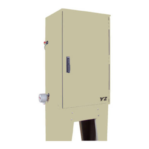
YZ Systems DynaPak DP-2010TP Installation instructions

DynaPak Gas Sampler
S Y S T E M S U P P O R T M A N U A L
DP-2010TP
DP-2010TP
I
NSTRUCTION
& O
PERATING
M
ANUAL
Version: 10012004
YZ Systems, Inc.  3101 Pollok Drive  Conroe, Texas  US  77303  P: 936.788.5593  F: 936.788.5720
Page IDP-2010 TP ver.10012004
DP-2010 TP TABLE OF CONTENTS
DP-2010 TP Table of Contents .........................................................................................................I
Section 1: First Things To Know ....................................................................................................1
How to Use this Manual .......................................................................................................................1
Typographic Conventions ....................................................................................................................1
Getting Help ......................................................................................................................................... 1
peration Specifications .....................................................................................................................2
Theory of peration ............................................................................................................................3
System Accessories ...........................................................................................................................4
Section 2: Syste Installation .........................................................................................................5
Standard System Components ...........................................................................................................5
System Flow Schematic .....................................................................................................................6
Standard System Mounting .................................................................................................................7
Standard System Connections ...........................................................................................................8
ptional DPS-2 Installation ................................................................................................................. 9
Section 3: Sa ple Vessel Installation ..........................................................................................11
Variable Pressure/Constant Volume Cylinders.................................................................................. 11
Link Plus ............................................................................................................................................ 11
Section 4: Syste Control & Electronics ....................................................................................13
verview ........................................................................................................................................... 13
Section 5: Progra ing for Proportional-to-Flow Operation ................................................... 15
Setting perator Input Parameters ................................................................................................... 15
Section 6: Progra ing For Proportional-To-Ti e Operation ................................................19
Setting perator Input Parameters ................................................................................................... 19
Section 7: Progra ing For Proportional-To-Ti e w/DPS-2 Operation .................................23
Setting perator Input Parameters ................................................................................................... 23
Section 8: Mechanical Syste ...................................................................................................... 27
DP-2000 Sample Pump .................................................................................................................... 28
YZ Filter Regulator ............................................................................................................................. 29
Section 9: Syste Operation .........................................................................................................31
Preparing The System For peration ...............................................................................................31
Electric Heater peration .................................................................................................................. 32
Section 10: Syste Maintenance ..................................................................................................35
Preventative Maintenance Schedule ................................................................................................. 35
Monthly Inspection .......................................................................................................................35
Semi-Annual Inspection ............................................................................................................... 35
Annual Inspection ........................................................................................................................35
Recommended Spare Parts ............................................................................................................. 35
Cleaning an Lubricating The Pump ................................................................................................... 36
Replacing a Depleted Battery ............................................................................................................38
Section 11: Syste Troubleshooting ............................................................................................ 41
How to Use This Section ...................................................................................................................41
For Additional Help .......................................................................................................................41
Step-by-Step Resolution ..............................................................................................................41
Battery Power....................................................................................................................................42
Battery Power Troubleshooting Steps .........................................................................................42
Z-65 Counter Mode ............................................................................................................................43
Z-65 Counter Mode Troubleshooting Steps ................................................................................. 43
Z-65 Timer Mode ...............................................................................................................................44
Z-65 Timer Mode Troubleshooting Steps ..................................................................................... 45
Appendix A: Illustrations ................................................................................................................ 49
DP-2000 Sample Pump Assembled ................................................................................................. 49
DP-2000 Sample Pump, Exploded View ........................................................................................... 50
Filter Regulator, Assembled .............................................................................................................. 51
Filter Regulator, Exploded View .........................................................................................................52
Link Plus ............................................................................................................................................ 53
ptional DPS-2 .................................................................................................................................54
Z-65 and Solenoid .............................................................................................................................55
Z-65 Wiring Control Document .........................................................................................................56
Electric Heater...................................................................................................................................57
YZ Systems, Inc.  3101 Pollok Drive  Conroe, Texas  US  77303  P: 936.788.5593  F: 936.788.5720
Page 1DP-2010 TP ver.10012004
SECTION 1: FIRST THINGS TO KNOW ABOUT THE DYNAPAK
How to Use this Manual
The DP-2010 perations Manual is a step-by-step
guide containing the procedures needed to work
with the DP-2010 System.
The DynaPak System Series of samplers implement
the most advanced technology available in the
industry. It is recommended that the technicians
working with the DynaPak Systems study the
manual prior to initiating work on the system for the
first time.
Typographic Conventions
To aide in readability, this manual uses several
typographic conventions. References to illustrations,
photographs, and other related content will appear in
italicized text along with the location of where to find the
item in the manual. Digital versions of the manual,
available in Adobe Acrobat PDF format, will be
highlighted further in blue italic text indicating the copy
retains a hyperlink to the referenced item.
Measurement units are listed in italic parenthesis text
following their US standard equivalent. As an example,
for defining a distance, 15' (4.5 meters), is how the text
will appear throughout the manual.
Items that require action, for example the pressing of a key
for programming the controller, will feature the action item in
sentence case Bold Text followed in normal text by the
item such as, the Up Arrow key or Main Power switch.
 dobe crobat & crobat Reader are trademarks of dobe Systems, Inc.
Getting Help
This manual provides solutions to typical questions
about the DP-2010 system. If the answer can not
be found within this manual, contact YZ Systems at:
T: 1.936.788.5593
T: 1.800.653.9435
F: 1.936.788.5720
Em: [email protected]
When calling, have this manual close at hand.
Whether calling or writing, please include in your
communique the following information:
 The serial number of the DynaPak System and
the version number of this manual. The serial
number is located on the inside of the enclosure
door. The version number of this manual is
located at the bottom of each page.
 A description of the problem and, if applicable the
actions of the technical personnel when the problem
occurred.
YZ Systems, Inc.  3101 Pollok Drive  Conroe, Texas  US  77303  P: 936.788.5593  F: 936.788.5720
Page 2 DP-2010 TP ver.10012004
SECTION 1: FIRST THINGS TO KNOW ABOUT THE DYNAPAK
Operation Specifications
Maximum utput: 5,760 cc/day*
(5.76 liters/day)
Maximum perating Pressure: 1,500 psig
(124 Bar (g)
Pump Displacement: .2 - .4 cc/Stroke
perating Temp Range: 0 to 140 degrees F.
(17°C to 6 °C)
Power Supply: Internal Battery Pack*
Flow Signal Dry Contact or
Voltage Pulse
Electric Heater Voltage 120 VAC
* The External Power Option can be used in
lieu of the internal battery pack. The External
Power ption (model # EP -120) consists of an
AC to DC convertor and intrinsically safe barrier
to convert 120 VAC power to 28 VDC to operate
the controller without the use of the internal
battery pack.
YZ Systems, Inc.  3101 Pollok Drive  Conroe, Texas  US  77303  P: 936.788.5593  F: 936.788.5720
Page 3DP-2010 TP ver.10012004
SECTION 1: FIRST THINGS TO KNOW ABOUT THE DYNAPAK
Theory of Operation
The DynaPak DP-2010TP Sampler is a pipeline
mounted system which uses the pneumatically
operated, positive displacement DynaPak 2000
pump, the Z-65 timer/controller, the YZ filter/
regulator and a low power solenoid valve to
obtain gas samples, while utilizing a catalytic
heated enclosure to aid in preventing the
sampled product from going through a phase
change, as temperatures, and pressures vary.
The 2010 provides three odes of operation:
A. Ti e-based sa pling: in this mode of
operation, the 2010 extracts a gas sample from
the pipeline at regular time intervals. The volume
of the sample is set by the operator using the
volume adjustment feature of the DP-2000
pump. The Z-65 controller operates as a recy-
cling timer, periodically energizing a low power
solenoid valve. Energizing the solenoid valve
allows actuation gas to stroke the DP-2000
pump. The rate at which this occurs is a func-
tion of operator input. Two 10 position switches
are used to set the off time interval. The number
of times the solenoid output is activated is
recorded by the onboard LCD stroke indicator.
B. Ti e-based sa pling with the YZ
differential pressure switch (DPS-2): this
mode of operation is similar to the time-based
sampling mode, except that the DPS-2 converts
a differential pressure signal to an electrical
signal that the Z-65 timer uses to determine if
flow is present in the pipeline. In effect, the DPS
allows the Z-65 timer to shut off when flow stops
in the pipeline, and when flow starts again, the
ability to start-up and resume operation.
C. Proportional-to-flow sa pling:
in this mode of operation, the Z-65 counter
operates as a dividing counter. The Z-65 counter
periodically energizes a low power solenoid
valve. As in the other two modes of operation,
this allows actuation gas to stroke the DP-2000
pump. The rate at which this occurs is a func-
tion of operator input as well as the host com-
puter or other device that inputs pulses per
volume metered. The two 10-position switches
on the Z-65 are used to set the number of pulses
the counter will count before activating the
solenoid output. The number of times the sole-
noid output is activated is recorded by the
onboard LCD stroke indicator. Sample volume is
again controlled using the DP-2000 volume
adjustment knob.
In all three modes of operation, the Z-65 timer/
counter operates using a replaceable internal
battery pack. The battery pack condition is
monitored by way of two indicator LEDs. When
the battery pack needs replacement, the red LED
will illuminate when the solenoid output is
activated. If the battery pack is good, the green
LED will illuminate when the solenoid is acti-
vated.
YZ Systems, Inc.  3101 Pollok Drive  Conroe, Texas  US  77303  P: 936.788.5593  F: 936.788.5720
Page 4 DP-2010 TP ver.10012004
SECTION 1: FIRST THINGS TO KNOW ABOUT THE DYNAPAK
System Accessories
 The External Power Option can be used in lieu of
the internal battery pack. The External Power
ption (model # EP -120) consists of an AC to
DC convertor and intrinsically safe barrier to
convert 120 VAC power to 28 VDC to operate the
controller without the use of the internal battery
pack.
 The Solar Power Option would be used in lieu of
the internal battery pack. The Solar Power Option
(model #SP -12) consists of a 5 watt solar panel
with RM-12 charger regulator module and internal
12V, 5 Amp hour battery pack.
SC-Spun Vessel, portable D T approved (1800 psi
maximum working pressure), sample vessels.
Available in 300, and 500 cc sizes.
KK-1, KK-2, & KK-3: carrying cases that meet D T
requirements for transporting portable sample
vessels.
 1/4" stainless steel tubing Dielectric Isolator Union.
These should be installed in every tubing line that
attaches the sampler to the pipeline in any
manner. For example the supply gas, product
connection to the system, and differential pres-
sure switch connections, (P/N A1- 182).
DPS-2 differential pressure switch for applications
with flow.no-flow conditiona and no flow signal
available.
LinkPlus provides a direct link between the
DynaPak, and your sample vessel, providing a
guage, vessel isolation valve, and excess pres-
sure protection.
A complete line of sampling accessories ranging
from sample probes to sample vessels is available
through YZ. Please contact your local representa-
tive or YZ toll free at 800.344.5399. For technical
support call 800.653.9435.
YZ Systems, Inc.  3101 Pollok Drive  Conroe, Texas  US  77303  P: 936.788.5593  F: 936.788.5720
Page 5DP-2010 TP ver.10012004
SECTION 2: SYSTEM INSTALLATION
Standard System Components
Standard primary components of the DynaPak 2010
include the following:
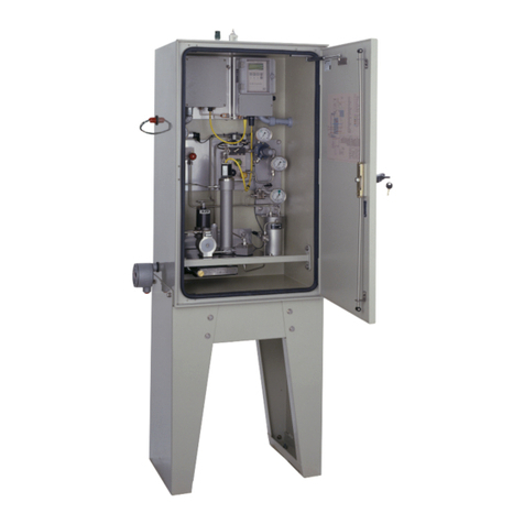
Syste Enclosure, figure 1 & 2. Houses the
Sample Pump, Filter Regulator, Solenoid, Spun
Cylinder Sample Vessel, Catalytic Heater, and
Temperature Guage.
Sa ple Pu p, figure 2. Probe mounted, pneumati-
cally actuated DP-2000 Sample Pump.
Filter Regulator, figure 2. Stainless Steel requlator capable
of reducing pressure from line pressure of up to 1500 psi
down to system supply pressures in one step.
Low Power Solenoid, figure 2. provides interface
between the Z-65 Electronic Controller, and the Pump
Pneumatic actuation.
Z-65 Controller Enclosure, figure 1, Provides a
weathertight enclosure for the Z-65 controller.
Z-65 Controller. figure 1. Provides control functions
for the DynaPak Sampler in Proportional-To-Flow,
or Proportional-To-Time Modes.
figure 1
S
V
L
figure 2
Enclosure Internal
Te perature Guage
Z-65 Controller
Enclosure
Syste Enclosure
Electric Heater
Junction
Enclosure
DP-2000 Sa ple Pu p
Filter Regulator
Low Power Solenoid





S
VL

(CEVQT[
5[UVGO
#RRTQXGF
/WVWCN
Custo er Supplied
Sa ple Probe
YZ Systems, Inc.  3101 Pollok Drive  Conroe, Texas  US  77303  P: 936.788.5593  F: 936.788.5720
Page 6 DP-2010 TP ver.10012004
SECTION 2: SYSTEM INSTALLATION
System Flow Schematic
figure 2
YZ Systems, Inc.  3101 Pollok Drive  Conroe, Texas  US  77303  P: 936.788.5593  F: 936.788.5720
Page 7DP-2010 TP ver.10012004
SECTION 2: SYSTEM INSTALLATION
Standard Mounting Location
1 The customer supplied sample probe should
be a minimum of five pipe diameters from any
device which could cause aerosols or significant
pressure drops.
2 The sample probe should not be located
within the defined meter tube region (AGA 3
manual).
A = The number of unobstructed, straight pipe
diameters upstream (see AGA - 3 manual).
B = The number of unobstructed, straight pipe
diameters downstream (see AGA - 3 manual).
0HWHU7XEH
2SWLPXP6DPSOHU3UREH/RFDWLRQV
'LIIHUHQWLDO3UHVVXUH'HYLFH

)ORZ
$ % 
figure 3
YZ Systems, Inc.  3101 Pollok Drive  Conroe, Texas  US  77303  P: 936.788.5593  F: 936.788.5720
Page 8 DP-2010 TP ver.10012004
SECTION 2: SYSTEM INSTALLATION
figure 4
Standard System Connections
a. The DynaPak 2010 sampler should be
mounted vertically on a horizontal run of the
pipeline.
b. The DynaPak 2010 requires a product connec-
tion to the pipeline via a customer supplied sample
probe, and 1/8 interconnecting stainless steel
tubing.
c. The end of the sampler probe should penetrate
the center 1/3rd of the pipeline.
d. The end of the sample probe should be cut
parallel to the pipeline.
e. Before applying pipeline pressure to the DynaPak 2010,
ensure that the isolation valve and purge valve are closed.
f. After pipeline pressure has been applied to the
sampler, check the probe body/pipeline connection
using a liquid leak detector.
CAUTION:
Incorrect operation of valves (over
tightening) can result in damage to the
valve components (isolation valve
bonnet assembly) which might result in
the valve stem being screwed out of the
probe body. This of course results in
product at pipeline pressure being
vented continually through this port
until this section of the pipeline is shut
in. Be aware of the following proce-
dures and information.
· DynaPak valves are of soft seat
design and should only be closed
or opened with fingers. No
wrenches should ever be used.
·If a valve will not seal off with
finger tight operation the valve
should have aintenance
perfor ed to allow proper
operation of the valve.
figure 5
S
VL





S
VL

(CEVQT[
5[ UV GO
#RRTQXGF
/WVWCN
(A) Custo er
Supplied
Sa ple Probe
(B) 1/8 S.S.
Tubing
(C)
YZ Systems, Inc.  3101 Pollok Drive  Conroe, Texas  US  77303  P: 936.788.5593  F: 936.788.5720
Page 9DP-2010 TP ver.10012004
SECTION 2: SYSTEM INSTALLATION
Optional DPS 2 Installation:
a. With the low pressure supply valve and the high
pressure supply valve closed, connect the DPS-2
to the orifice connection tubing.
b. pen the equalization valve.
c. pen the low pressure supply valve or the high
pressure supply valve.
IMPORTANT NOTE:
Do not open either the low pressure supply valve
or the high pressure supply valve without ensuring
that the equalization valve is open. Failure to do
so may damage the DPS-2's internal components.
d. pen the other supply valve.
e. Close the equalization valve.
f. Run the free end of the DPS-2 cable through
the cable entry connector located on the upper left
side on the DynaPak 2010 enclosure.
g. Connect the DPS-2 cable as shown in the
diagram.
h. Tighten the cable entry connector, allowing for
enough cable length to open the enclosure.
High Pressure Supply Valve
Orifice Connection
Equalization Valve
Low Pressure Supply Valve
Flow
Low Pressure
High Pressure
(CEVQT[
#RRTQXGF
5[UVGO
/WVWCN
Clear
Black
IMPORTANT NOTE:
For the Z-65 to operate the DP-2 1 System, a
minimum pressure differential of 3" of water must
exist between the high pressure and low pressure
ports of the DPS-2.
figure 6
YZ Systems, Inc.  3101 Pollok Drive  Conroe, Texas  US  77303  P: 936.788.5593  F: 936.788.5720
Page 10 DP-2010 TP ver.10012004
SECTION 2: SYSTEM INSTALLATION
Notes
YZ Systems, Inc.  3101 Pollok Drive  Conroe, Texas  US  77303  P: 936.788.5593  F: 936.788.5720
Page 11DP-2010 TP ver.10012004
SECTION 3: SAMPLE VESSEL INSTALLATION
Variable Pressure/
Constant Volu e Cylinders.
Spun cylinders may be installed in a vertical
position on the DynaPak SC vessel manifold.
Stainless steel tubing and fittings from the
sample discharge port of the sampler are pre-
installed to the product end of the sample cylin-
der, when installed in this manner.
LinkPlus. Install the optional LinkPlus directly
into the sample discharge port of the sampler.
Use stainless steel tubing and fittings to connect
the LinkPlus outlet to the product end of the
sample cylinder.
LinkPlus
Filter Regulator
Sa ple Pu p
S
V
L
Custo er
Supplied
Sa ple Probe
Variable Pressure/
Constant Volu e Cylinder
YZ Systems, Inc.  3101 Pollok Drive  Conroe, Texas  US  77303  P: 936.788.5593  F: 936.788.5720
Page 12 DP-2010 TP ver.10012004
SECTION 3: SAMPLE VESSEL INSTALLATION
Notes
YZ Systems, Inc.  3101 Pollok Drive  Conroe, Texas  US  77303  P: 936.788.5593  F: 936.788.5720
Page 13DP-2010 TP ver.10012004
SECTION 4: SYSTEM CONTROL & ELECTRONICSSECTION 4: SYSTEM CONTROL & ELECTRONICS
The electronic control package provided with
your sampling system consists of a solid state
Z-65 Controller, and a Low Powered Solenoid.
The Z-65 energizes the solenoid which in turn
sends a pneumatic actuation signal to the
Sample Pump, every time a sample is required
either Proportional-To-Flow, or Time.
SAFETY NOTES
 Always use extreme care when performing mainte-
nance on Sampling Systems. Always take necessary
measures to assure that electrical classification in the
area is considered, before, and during all repairs, and
that necessary steps are taken to maintain proper
electrical procedures for the classification of the area.
The control package requires you to configure
the Z-65 controller to operate in a Proportional-
To-Flow mode, refer Section 5, to page 16, a
Proportional-To-Time mode, refer toSection 6,
page 19, or with the use of an optional DPS-2
switch a Proportional-To-Time w/DPS-2 mode,
refer to Section 7, page 23. All wiring connected
to the Z-65 controller must be done in accor-
dance with the Wiring Control Document, refer
to Appendix A, page 47. DynaPak electronics
are rated for use in Class I, Division 1, Groups C
and D hazardous locations.
Overview
YZ Systems, Inc.  3101 Pollok Drive  Conroe, Texas  US  77303  P: 936.788.5593  F: 936.788.5720
Page 14 DP-2010 TP ver.10012004
SECTION 4: SYSTEM CONTROL & ELECTRONICS
Notes

Other YZ Systems Industrial Equipment manuals

YZ Systems NJEX ZEO 6400 Parts list manual

YZ Systems

YZ Systems NJEX ZEO 6400 Parts list manual

YZ Systems NJEX 8300G User manual

YZ Systems

YZ Systems NJEX 8300G User manual

YZ Systems DynaPak 2010XHK User guide

YZ Systems

YZ Systems DynaPak 2010XHK User guide

YZ Systems DynaPak 2010 Series Installation instructions

YZ Systems

YZ Systems DynaPak 2010 Series Installation instructions

YZ Systems DynaPak 3010RNM Series Installation instructions

YZ Systems

YZ Systems DynaPak 3010RNM Series Installation instructions

YZ Systems NJEX 6300G Parts list manual

YZ Systems

YZ Systems NJEX 6300G Parts list manual

YZ Systems DynaPak 2010 Series Installation instructions

YZ Systems

YZ Systems DynaPak 2010 Series Installation instructions

YZ Systems DynaPak 2010LF Series Installation instructions

YZ Systems

YZ Systems DynaPak 2010LF Series Installation instructions

YZ Systems DynaPak 2010 Series Installation instructions

YZ Systems

YZ Systems DynaPak 2010 Series Installation instructions

YZ Systems NJEX 610G Parts list manual

YZ Systems

YZ Systems NJEX 610G Parts list manual

YZ Systems DynaPak 2010 Series Installation instructions

YZ Systems

YZ Systems DynaPak 2010 Series Installation instructions

YZ Systems NJEX 610G Parts list manual

YZ Systems

YZ Systems NJEX 610G Parts list manual

YZ Systems DynaPak 2010 Series Installation instructions

YZ Systems

YZ Systems DynaPak 2010 Series Installation instructions

YZ Systems DynaPak 2010 Series Installation instructions

YZ Systems

YZ Systems DynaPak 2010 Series Installation instructions

YZ Systems NJEX 7300L Parts list manual

YZ Systems

YZ Systems NJEX 7300L Parts list manual

YZ Systems NJEX 7300G Parts list manual

YZ Systems

YZ Systems NJEX 7300G Parts list manual

Popular Industrial Equipment manuals by other brands

Spirax Sarco BPS32 Installation and maintenance instructions

Spirax Sarco

Spirax Sarco BPS32 Installation and maintenance instructions

Sealey PT1000G.V2 manual

Sealey

Sealey PT1000G.V2 manual

Kitagawa TW2180BRF5 instruction manual

Kitagawa

Kitagawa TW2180BRF5 instruction manual

SMC Networks MWB 32-UT Series Operation manual

SMC Networks

SMC Networks MWB 32-UT Series Operation manual

TSI Instruments Amermac 405-W operating manual

TSI Instruments

TSI Instruments Amermac 405-W operating manual

Ecolab Chameleon PLUS BW3 Service manual

Ecolab

Ecolab Chameleon PLUS BW3 Service manual

Orca RUNplus instruction manual

Orca

Orca RUNplus instruction manual

MARCOLIN Ecotype installation manual

MARCOLIN

MARCOLIN Ecotype installation manual

Sealey SSG1P/3.V3 quick start guide

Sealey

Sealey SSG1P/3.V3 quick start guide

Milnor COSHN111 Installation and service

Milnor

Milnor COSHN111 Installation and service

Siemens 3TX7462-3 Series operating instructions

Siemens

Siemens 3TX7462-3 Series operating instructions

STOKVIS ENERGY SYSTEMS ECONOPLATE E3 Series Installation, operation & maintenance documentation

STOKVIS ENERGY SYSTEMS

STOKVIS ENERGY SYSTEMS ECONOPLATE E3 Series Installation, operation & maintenance documentation

Parker J Series Maintenance Bulletin

Parker

Parker J Series Maintenance Bulletin

Siemens 3VT9300-4ED30 operating instructions

Siemens

Siemens 3VT9300-4ED30 operating instructions

Roemheld 8910-01-20-H operating instructions

Roemheld

Roemheld 8910-01-20-H operating instructions

MULTIQUIP GLOBUG Series Operation and parts manual

MULTIQUIP

MULTIQUIP GLOBUG Series Operation and parts manual

MAKSIWA CBC.P user manual

MAKSIWA

MAKSIWA CBC.P user manual

JB INDUSTRIES REVOLVER 26233 quick start guide

JB INDUSTRIES

JB INDUSTRIES REVOLVER 26233 quick start guide

manuals.online logo
manuals.online logoBrands
  • About & Mission
  • Contact us
  • Privacy Policy
  • Terms and Conditions

Copyright 2025 Manuals.Online. All Rights Reserved.