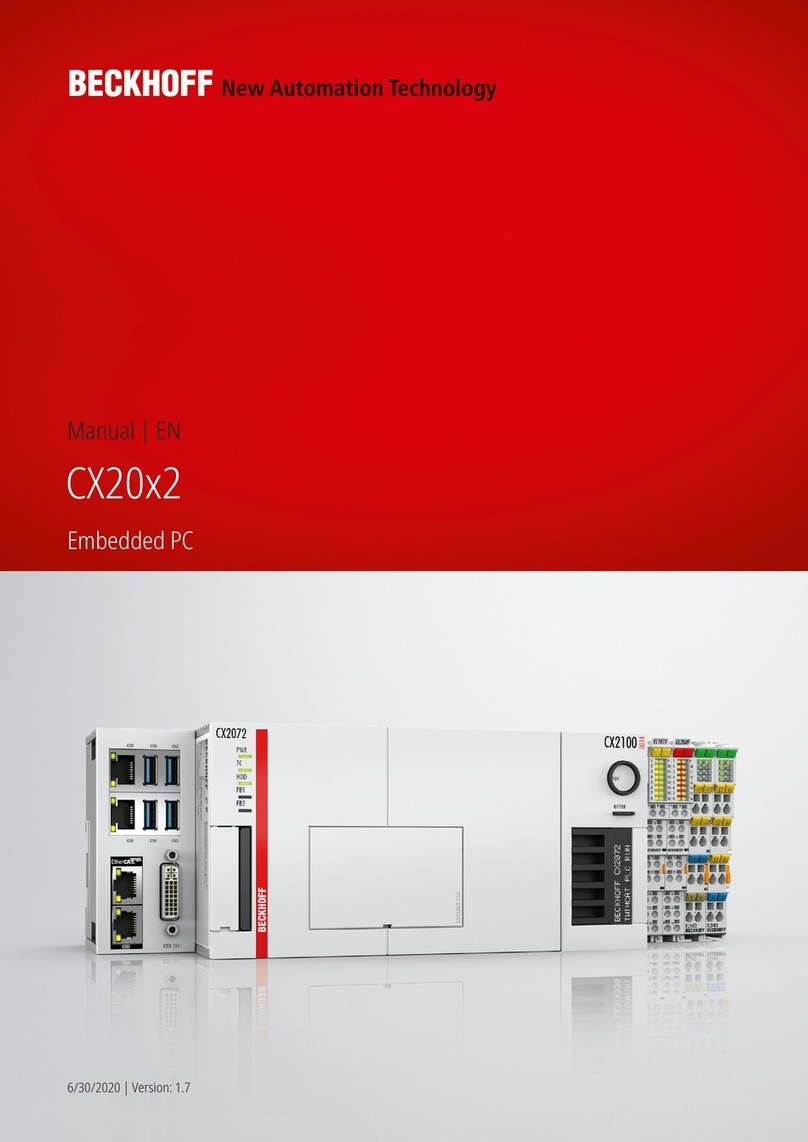
Beckhoff CX2020 User manual

Manual
CX2020, CX2030, CX2040
Embedded PC
1.2
01/03/2014
CX20x001xx
Version
Date
Order No.


Table of contents
Table of contents
1 Foreword .................................................................................................................................................... 4
1.1 Notes on the documentation................................................................................................................ 4
1.2 Safety instructions ............................................................................................................................... 5
1.3 Documentation issue state .................................................................................................................. 6
2 Product overview ....................................................................................................................................... 7
2.1 Intended use ........................................................................................................................................ 7
2.2 System Overview................................................................................................................................. 8
2.3 CX20x0 Technical data ................................................................................................................... 11
2.4 Types................................................................................................................................................. 13
2.5 Architeture overview .......................................................................................................................... 15
2.6 Battery compartment ......................................................................................................................... 16
2.7 CF slot ............................................................................................................................................... 16
2.8 CFast card ......................................................................................................................................... 17
3 Mounting and wiring................................................................................................................................ 18
3.1 Unpacking, installation and transport ................................................................................................ 18
3.2 Dimensions........................................................................................................................................ 19
3.3 Installation on the mounting rail......................................................................................................... 20
3.4 Mounting the module lock.................................................................................................................. 22
3.5 Power supply ..................................................................................................................................... 24
3.6 Mounting of passive terminals on the CX21000xx4 power supply ................................................... 26
3.7 DVII port ........................................................................................................................................... 27
3.8 USB connections ............................................................................................................................... 29
3.9 LAN connections ............................................................................................................................... 30
3.10 RS232 connections (CX20x0N030) ................................................................................................. 31
3.11 RS422/RS485 connections (CX20x0N031) ..................................................................................... 32
4 Commissioning / Configuration ............................................................................................................. 34
4.1 EtherCAT cable redundancy ............................................................................................................. 34
4.2 Switching on and off .......................................................................................................................... 37
5 Error handling and diagnostics.............................................................................................................. 38
5.1 Basic CPU module ............................................................................................................................ 38
5.1.1 LEDs on the basic CPU module ............................................................................................. 38
5.1.2 LEDs of the power supply (CX21000004) in KBus mode .................................................... 38
5.1.3 LEDs of the power supply (CX21000004) in EBus mode .................................................... 40
5.2 Faults................................................................................................................................................. 41
6 Decommissioning .................................................................................................................................... 42
6.1 Disassembly and disposal ................................................................................................................. 42
7 Appendix .................................................................................................................................................. 44
7.1 Accessories ....................................................................................................................................... 44
7.2 Certifications ...................................................................................................................................... 45
7.3 Support and Service .......................................................................................................................... 46
CX2020, CX2030, CX2040 iii
Version 1.2
Foreword
1 Foreword
1.1 Notes on the documentation
This description is only intended for the use of trained specialists in control and automation engineering who
are familiar with the applicable national standards.
It is essential that the following notes and explanations are followed when installing and commissioning
these components.
The responsible staff must ensure that the application or use of the products described satisfy all the
requirements for safety, including all the relevant laws, regulations, guidelines and standards.
Disclaimer
The documentation has been prepared with care. The products described are, however, constantly under
development.
For that reason the documentation is not in every case checked for consistency with performance data,
standards or other characteristics.
In the event that it contains technical or editorial errors, we retain the right to make alterations at any time
and without warning.
No claims for the modification of products that have already been supplied may be made on the basis of the
data, diagrams and descriptions in this documentation.
Trademarks
Beckhoff
®
, TwinCAT
®
, EtherCAT
®
, Safety over EtherCAT
®
, TwinSAFE
®
, XFC
®
and XTS
®
are registered
trademarks of and licensed by Beckhoff Automation GmbH.
Other designations used in this publication may be trademarks whose use by third parties for their own
purposes could violate the rights of the owners.
Patent Pending
The EtherCAT Technology is covered, including but not limited to the following patent applications and
patents:
EP1590927, EP1789857, DE102004044764, DE102007017835
with corresponding applications or registrations in various other countries.
The TwinCAT Technology is covered, including but not limited to the following patent applications and
patents:
EP0851348, US6167425 with corresponding applications or registrations in various other countries.
Copyright
© Beckhoff Automation GmbH, Germany.
The reproduction, distribution and utilization of this document as well as the communication of its contents to
others without express authorization are prohibited.
Offenders will be held liable for the payment of damages. All rights reserved in the event of the grant of a
patent, utility model or design.
CX2020, CX2030, CX20404Version 1.2

Foreword
1.2 Safety instructions
Safety rules
Consider the following safety instructions and descriptions!
Product specific safety instructions are to be found on the following pages or in the areas mounting, wiring,
commissioning etc.
Disclaimer
All the components are supplied in particular hardware and software configurations appropriate for the
application. Modifications to hardware or software configurations other than those described in the
documentation are not permitted, and nullify the liability of Beckhoff Automation GmbH.
Personnel qualification
This description is only intended for the use of trained specialists in control, automation and drive
engineering who are familiar with the applicable national standards.
Description of symbols
The following symbols with a adjoining safety advise or notice are used in this documentation. You have to
read the safety advices carefully and adhere them strictly!
DANGER
Acute risk of injury!
If you do not adhere the safety advise adjoining this symbol, there is immediate danger to
life and health of individuals!
WARNING
Risk of injury!
If you do not adhere the safety advise adjoining this symbol, there is danger to life and
health of individuals!
CAUTION
Hazard to individuals!
If you do not adhere the safety advise adjoining this symbol, there is obvious hazard to indi
viduals!
Attention
Hazard to devices and environment
If you do not adhere the notice adjoining this symbol, there is obvious hazard to materials
and environment.
Notice
Note or pointer
This symbol indicates information that contributes to better understanding.
CX2020, CX2030, CX2040 5
Version 1.2

Foreword
1.3 Documentation issue state
Version Changes
1.0 First Version
1.1 Notes on power connections added, order numbers
for CX20x0N031 added
1.2 New types added
CX2020, CX2030, CX20406Version 1.2

Product overview
2 Product overview
2.1 Intended use
The CX20x0 device series is a modular control system designed for tophat rail installation. The system is
scalable, so that the required modules can be assembled and installed in the control cabinet or terminal box
as required.
Only switch the PC off after closing the software
Before the Embedded PC is switched off, the software currently running on it should be stopped properly in
order to avoid data loss on the hard disk. Please read the section on “Switching off”.
Switch off all system components and uncouple the Industrial PC from the system if the PC is not used for
control purposes, e.g. during a function test. To disconnect first pull the first terminal behind the power
supply unit (optional), then pull the connectors of the fieldbus connections.
System components that have been switched off must be secured against being switched on again.
The Embedded PC’s power supply unit must be supplied with 24 V
DC
.
Attention
Damage to the environment or devices
Do not exchange any parts when under power! The exchange of controller parts when live
can lead to shortcircuits or overvoltages. These can damage the controller itself and con
nected peripherals (terminals, monitors, input devices, etc.).
When components are being fitted or removed, the supply voltage must be switched off.
Software knowledge
Attention
System malfunctions
Mandatory software knowledge! Every user must be familiar with any of the functions of the
software installed on the PC that he can reach.
CX2020, CX2030, CX2040 7
Version 1.2

Product overview
2.2 System Overview
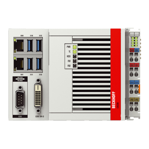
CX2020, CX2030, CX2040 | Basic CPU module
The system
The CX2020 has a 1.4 GHz Intel® Celeron® CPU, the CX2030 has a 1.5 GHz Intel® Core™ i7 dualcore
CPU, the CX2040 has a 2.1 GHz Intel® Core™ i7 quadcore CPU. In the CX2020 and CX2030 the controller
is fanless and has no rotating components. Due to its high power, the CX2040 has a fan with ball bearings
and speed monitoring. In addition to the CPU and chipset the basic modules also contain the main memory.
For the CX2020 and CX2030 the size is 2 GB. Up to 4 GB are possible as an option. The CX2040 has 4 GB
of RAM as standard. The controller boots from the CFast flash memory card. The basic configuration of the
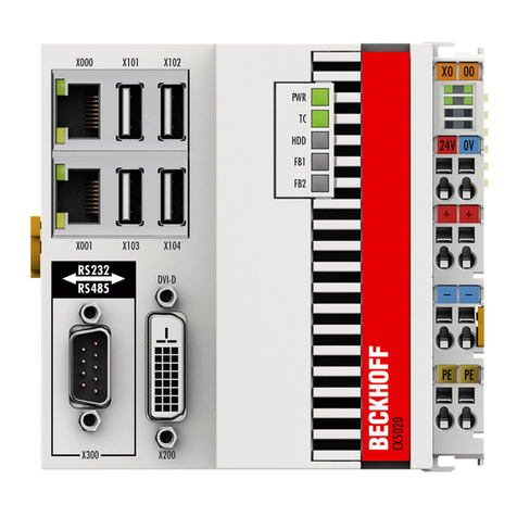
modules includes a CFast memory card, two independent Gbit Ethernet interfaces, four USB 2.0 interfaces
and a DVII interface. The CPU has an internal 128 KB NOVRAM, which functions as a persistent data
memory if no UPS is used. Optionally the devices can be ordered with a serial or fieldbus interface. Other
components from the CX2000 family can be connected via the multipin terminals on either side. The
operating system is Microsoft Windows Embedded Standard 7 P. Up to four modules can be connected to
the basic CPU module. The connection order is irrelevant. Internally the modules are connected via PCI
Express and can be plugged to the CPU "in the field". The power supply for the CPU module comes from a
CX2100 power supply module, which is connected on the righthand side of the CPU. Two further CFast
memory card modules (CX2550 0010) can be connected between the power supply unit and the CPU, so
that a total of up to three CFast cards can be used. RAID can be used in situations where more than one
CFast card is used.
The CX2020, CX2030 and CX2040 Embedded PCs extend the CX product family with versions with very
high CPU power (optionally with multicore) and enable direct connection of Bus Terminals or EtherCAT
Terminals. The CX2000 in conjunction with EtherCAT and TwinCAT enables very fast control processes in
the microsecond range (eXtreme Fast Control Technology). The basic CPU modules have two independent
Gbit Ethernet interfaces, four USB 2.0 interfaces and a DVII interface as standard. A serial or a fieldbus
interface can optionally be ordered. Please note that these have to be specified with the order, i.e.
CX2020, CX2030, CX20408Version 1.2

Product overview
retrospective installation is not possible. On the lefthand side the CPU features a multipin connector for
connecting further optional modules.
The components
The individual system components are modules with a width of 22 mm or multiples of it that can be
connected inline with one another. The basic unit consists of the CX20x0 CPU module and a power supply
module (CX21000xxx).
Power supply unit with integrated I/O interface and optional UPS
The 24V DC power supply unit is available in three different versions:
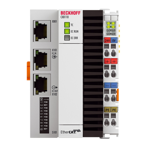
• CX21000004: Ebus/KBus power supply unit with automatic switchover
• CX21000904: Ebus/KBus power supply unit with automatic switchover and integrated capacitive
UPS
• CX21000914: Ebus/KBus power supply unit with automatic switchover and integrated electronic
charging unit for external battery packs in order to maintain UPS functionality.
All power supply units feature an illuminated antiglare LC display with two rows of 16 characters each for
displaying status messages. The application programs can also use the display for displaying application
specific texts.
EtherCAT as a fast I/O system
The CX2020, CX2030 and CX2040 Embedded PCs were developed with a view towards optimised
interaction with EtherCAT. EtherCAT offers a wide range of application options. The separate Gigabit
Ethernet interfaces enable EtherCAT to be used with cable redundancy by using one of the Ethernet
interfaces as redundancy port. In addition, devices with EtherCAT slave interface can be operated such that
several intelligent controllers can be synchronised via an EtherCAT network.
PLC, Motion Control, interpolation and visualisation
As IPC on a DIN rail the CX2000 in conjunction with TwinCAT offers the functionality of large Industrial PCs.
Multicore CPUs in conjunction with TwinCAT 3 enable PLC projects to be distributed to several cores,
resulting in significant performance gains. Moreover, all TwinCAT functionalities are available for Motion
Control applications: in theory, up to 256 axes can be controlled. In addition to simple pointtopoint
movements, more complex multiaxis functions such as “electronic gearbox”, “cam plates” and “flying saw”
can be implemented. Due to the highperformance CPUs, the CX2000 can also perform interpolating 3D
path movements and execute DIN66025 programs. In addition to handling realtime control tasks the
TwinCAT realtime kernel leaves enough time for the user interface (HMI). The high performance of the
graphics kernel integrated in the CPU enables demanding visualisations with advanced user interfaces to be
realised.
Fieldbus interfaces
The fieldbus interfaces are currently available as master and slave versions for the following fieldbuses.
Optional interfaces:
The optional interfaces can be used to connect singlechannel fieldbus interfaces. Operation is limited to one
interface at a time. If several fieldbus interfaces are required, they can be added as Ebus terminals
(EL67xx). The following fieldbus interfaces are available:
• CX20x0N010 = DVID, DVID connector
• CX20x0N030 = RS232, DSub connector
• CX20x0N031 = RS422/RS485, DSub socket
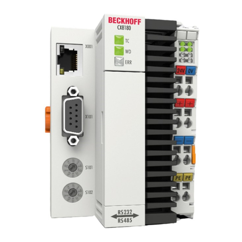
• CX20x0B110 = EtherCAT slave, EtherCAT IN and OUT (2 x RJ 45)
• CX20x0M310 = PROFIBUS master, DSub socket, 9pin
CX2020, CX2030, CX2040 9
Version 1.2

Product overview
• CX20x0B310 = PROFIBUS slave, DSub socket, 9pin
• CX20x0M510 = CANopen master, DSub connector, 9pin
• CX20x0B510 = CANopen slave, DSub connector, 9pin
• CX20x0M930 = PROFINET RT, controller, Ethernet (2 x RJ45)
• CX20x0B930 = PROFINET RT, device, Ethernet (2 x RJ45 switch)
• CX20x0B950 = EtherNet/IP Slave, Ethernet (2 x RJ45 switch)
The software
In combination with the TwinCAT automation software, the CX20x0 Industrial PC becomes a powerful IEC
611313 PLC with up to four user tasks. Additionally, Motion Control tasks can also be executed. Depending
on the required cycle time, several servo axes can be controlled. Even special functions such as flying saw,
electronic gearbox and cam plate can be realised.
CX2020, CX2030, CX204010 Version 1.2

Product overview
2.3 CX20x0 Technical data
The basic configuration of the CX20x0 includes an 8 GB CFast Flash card. The basic configuration includes
two Ethernet RJ45 interfaces, four USB2.0 interfaces and a DVII interface.
Technical data CX2020 CX2030 CX2040
Processor Intel® Celeron® 1.4 GHz,
singlecore
Intel® Core
TM
i7 1,5 GHz,
dualcore
Intel® Core
TM
i7 2,1 GHz,
quadcore
Internal Flash memory 4 or 8 GB CFast Flash
card (optionally expand
able)
4 or 8 GB CFast Flash
card (optionally expand
able)
4 or 8 GB CFast Flash
card (optionally expand
able)
Internal main memory 2 GB DDR3RAM 2 GB DDR3RAM 4 GB DDR3RAM
Persistent memory 128 kB NOVRAM inte
grated
128 kB NOVRAM inte
grated
128 kB NOVRAM inte
grated
Interfaces 2 x RJ 45, 10/100/1000
MBit/s, DVII, 4 x USB
2.0, 1x option interface
2 x RJ 45, 10/100/1000
MBit/s, DVII, 4 x USB
2.0, 1x option interface
2 x RJ 45, 10/100/1000
MBit/s, DVII, 4 x USB
2.0, 1x option interface
Diagnostics LED 1 x power, 1 x TC status,
1 x flash access, 2 x bus
status
1 x power, 1 x TC status,
1 x flash access, 2 x bus
status
1 x power, 1 x TC status,
1 x flash access, 2 x bus
status
Clock Internal clock with battery
backup for time and date
(battery replaceable)
Internal clock with battery
backup for time and date
(battery replaceable)
Internal clock with battery
backup for time and date
(battery replaceable)
Operating system Microsoft Windows
Embedded Standard 7 P
Microsoft Windows
Embedded Standard 7 P
Microsoft Windows
Embedded Standard 7 P
Control software TwinCAT 2 PLC Runtime,
NC PTP Runtime, NC I
Runtime | TwinCAT 3.
See TwinCAT 3 price list
TwinCAT 2 PLC Runtime,
NC PTP Runtime, NC I
Runtime | TwinCAT 3.
See TwinCAT 3 price list
TwinCAT 2 PLC Runtime,
NC PTP Runtime, NC I
Runtime | TwinCAT 3.
See TwinCAT 3 price list
Power supply 24 V DC (15 %/+20 %) 24 V DC (15 %/+20 %) 24 V DC (15 %/+20 %)
Max. power loss 15 W (including system in
terfaces)
20 W (including system in
terfaces)
42 W (including system in
terfaces)
Dielectric strength 500 V (supply / internal
electronics)
500 V (supply / internal
electronics)
500 V (supply / internal
electronics)
Dimensions (W x H x D) 144 mm x 100 mm x 91
mm
144 mm x 100 mm x 91
mm
144 mm x 100 mm x 91
mm
Weight approx. 1,160 g approx. 1,165 g approx. 1,230 g
Operating/storage temper
ature
25° C ... +60° C / 40°
C ... +85° C
25° C ... +60° C / 40°
C ... +85° C
25° C ... +60° C / 40°
C ... +85° C
Relative humidity 95 % no condensation 95 % no condensation 95 % no condensation
CX2020, CX2030, CX2040 11
Version 1.2

Product overview
Technical data CX2020 CX2030 CX2040
Vibration/shock resistant conforms to EN
6006826 / EN
60068227
conforms to EN
6006826 / EN
60068227
conforms to EN
6006826 / EN
60068227
EMC immunity/emission conforms to EN
6100062 / EN 6100064
conforms to EN
6100062 / EN 6100064
conforms to EN
6100062 / EN 6100064
Protection class IP 20 IP 20 IP 20
Further Information: www.beckhoff.de/ CX2000
CX2020, CX2030, CX204012 Version 1.2

Product overview
2.4 Types
The CPU module can be equipped with different hardware and software options. The TwinCAT automation
software transforms a CX20x0 system into powerful PLC and Motion Control system that can be operated
with or without visualisation. Further system interfaces (preinstalled in the factory) or fieldbus connections
can be added to the basic CPU module.
The CX 20x0 modules are available in the following types:
Table 1: CX2020 (1,4 GHz 1 core)
Modul without
Operat
ingsys
tem
Microsoft
Windows
Embedded
Compact
Microsoft
Windows
Embedded7
(32bit)
Microsoft
Windows
Embedded7
(64bit)
without
TwinCAT
TwinCAT
PLC
Runtime
TwinCAT
NC PTP
Runtime
TwinCAT
NC I
Runtime
CX20200100 X X
CX20200110 X X
CX20200120 X X
CX20200130 X X
CX20200111 X X
CX20200112 X X
CX20200113 X X
CX20200121 X X
CX20200122 X X
CX20200123 X X
CX20200131 X X
CX20200132 X X
CX20200133 X X
Table 2: CX2030 (1,5 GHz 2 cores)
Modul without
Operat
ingsys
tem
Microsoft
Windows
Embedded
Compact
Microsoft
Windows
Embedded7
(32bit)
Microsoft
Windows
Embedded7
(64bit)
without
TwinCAT
TwinCAT
PLC
Runtime
TwinCAT
NC PTP
Runtime
TwinCAT
NC I
Runtime
CX20300100 X X
CX20300110 X X
CX20300120 X X
CX20300130 X X
CX20300111 X X
CX20300112 X X
CX20300113 X X
CX2020, CX2030, CX2040 13
Version 1.2

Product overview
Modul without
Operat
ingsys
tem
Microsoft
Windows
Embedded
Compact
Microsoft
Windows
Embedded7
(32bit)
Microsoft
Windows
Embedded7
(64bit)
without
TwinCAT
TwinCAT
PLC
Runtime
TwinCAT
NC PTP
Runtime
TwinCAT
NC I
Runtime
CX20300121 X X
CX20300122 X X
CX20300123 X X
CX20300131 X X
CX20300132 X X
CX20300133 X X
Table 3: CX2040 (2,1 GHz 4 cores)
Modul without
Operat
ingsys
tem
Microsoft
Windows
Embedded
Compact
Microsoft
Windows
Embedded7
(32bit)
Microsoft
Windows
Embedded7
(64bit)
without
TwinCAT
TwinCAT
PLC
Runtime
TwinCAT
NC PTP
Runtime
TwinCAT
NC I
Runtime
CX20400100 X X
CX20400110 X X
CX20400120 X X
CX20400130 X X
CX20400111 X X
CX20400112 X X
CX20400113 X X
CX20400121 X X
CX20400122 X X
CX20400123 X X
CX20400131 X X
CX20400132 X X
CX20400133 X X
CX20x0 systems with Microsoft Windows Embedded 7 P require a Compact Flash card with a capacity of at
least 8 GByte.
Notice
Software Images
A list of the different software images can be found in the CX1000 Software Documenta
tion.
CX2020, CX2030, CX204014 Version 1.2

Product overview
2.5 Architeture overview
CX2020, CX2030, CX2040 15Version 1.2

Product overview
2.6 Battery compartment
The battery compartment is located under the front cover of the CX20x0. The opening in which the battery
bracket is mounted can be seen when the front cover is opened. The battery is then pulled carefully out of
the holder with the help of the ejection tab and then removed.
To insert a new battery push it into the battery compartment. Ensure correct polarity. Then close the front
cover. The battery change is then complete.
The battery is a CR2032 type from Panasonic.
The correct specifications are:
Battery type Electrical properties (at 20
°C)
Standard
charge
Dimensions
nominal
voltage
nominal ca
pacity
continuous
load
Diameter Height Weight
CR2032 3.0 V 225 mAh 0.20 mA 20.0 mm 3.20 mm 3.1 g
Attention
An incorrectly inserted battery may explode!
Only use the same battery type (CR2032) from Sanyo or Panasonic. Make absolutely sure
that positive and negative terminals of the battery are inserted correctly. (minus pole on the
left)Never open the battery or throw it into a fire.The battery cannot be recharged.
Notice
Battery maintenance
The battery must be replaced every 5 years. Spare batteries can be ordered from Beckhoff
Ser v i ce [ }46].
2.7 CF slot
A CFast Flash slot is located at the front, which enables the storage medium to be replaced. This allows the
storage medium to be exchanged. In the basic module this should only be done in switchedoff state,
otherwise the system may crash. The CFast Flash card can be removed from the module for maintenance.
In this way it is also possible to expand the system (only operating system and program memory). CFast
Flash cards (CFast cards) are available as accessories in various sizes.
The following images illustrate the handling of the CFast cards. The eject mechanism is based on the push
push principle: The CFast Flash card is disengaged with a soft click by lightly pressing the card. At the same
time the card moves approx. 4 mm out of the housing, so that it can be pulled out.
CX2020, CX2030, CX204016 Version 1.2

Product overview
On inserting the CFast Flash card it engages again with a soft click. The card is seated correctly if it is flush
with the front side of the device housing.
2.8 CFast card
The CFast Flash Card (CFast Card) is a nonvolatile memory.
Data to be retained in the event of a power failure should be saved on the CFast card. The CFast card
operates like a hard disk.
Notice
Using CFast cards
We strongly recommend that only CFast cards supplied by Beckhoff Automation GmbH
should be used. These are industrial CF cards with a higher number of write/read cycles
and an extended temperature range (+85 °C). Proper operation can only be guaranteed
with CFast cards from Beckhoff Automation GmbH!
CX2020, CX2030, CX2040 17
Version 1.2

Mounting and wiring
3 Mounting and wiring
3.1 Unpacking, installation and transport
The specified storage conditions must be adhered to (see "Technical data").
Dimensions and weight of the individual modules:
Dimensions (W x H x D): 144 mm x 100 mm x 91 mm
Weight: approx. 1160 g / 1165g / 1230 g (basic module)
Unpacking
Proceed as follows to unpack the unit:
1. Remove packaging.
2. Do not discard the original packaging. Keep it for transporting the device in the future.
3. Check the delivery for completeness by comparing it with your order.
4. Please keep the associated paperwork. It contains important information for handling the unit.
5. Check the contents for visible shipping damage.
6. If you notice any shipping damage or inconsistencies between the contents and your order, you
should notify Beckhoff Service.
Attention
Danger of damage to the unit!
During transport in cold conditions, or if the unit is subjected to extreme temperature
swings, condensation on and inside the unit must be avoided. Prior to operation, the unit
must be allowed to slowly adjust to room temperature. Should condensation occur, a delay
time of approximately 12 hours must be allowed before the unit is switched on.
Installation
The devices are designed for installation in control cabinets.
Shipping and relocation
Despite the robust design of the unit, the components are sensitive to strong vibrations and impacts. During
transport, your computer should therefore be protected from excessive mechanical stress. Therefore, please
use the original packaging.
CX2020, CX2030, CX204018 Version 1.2

Mounting and wiring
3.2 Dimensions
The following drawings show the dimensions of the CX20x0 devices.
Dimensions
CX2020, CX2030, CX2040 19Version 1.2

Mounting and wiring
3.3 Installation on the mounting rail
Snapping onto the mounting rail
The CX20x0 can simply be snapped onto the mounting rail. The bar clips are inserted on the top side and
underside Then simply position the block on the mounting rail and push it slightly until it engages on the
righthand side. This is indicated by a distinct click. The bars are then engaged again. The engagement of
the individual bars is indicated by a distinct click.
Attention
Avoid damage!
Do not force the module or apply excessive pressure!
Installation position
Attention
Comply with the permitted installation position and minimum distances!
The maximum ambient temperature for CPU modules mounted on a tophat rail is 60°C.
The orientation in which the device is fitted must be selected in such a way that cooling air
can flow vertically through the ventilation holes. The images below show the permitted and
two incorrect installation positions. Mounting must provide a clearance of 30 mm both
above and below a CX20x0 device combination to ensure adequate ventilation of the base
CPU module and the power supply unit.
Correct installation position
The high performance and the compact design of the CX20x0 systems may result in increased heat
generation. The heat is dissipated via a passive ventilation system. This system requires the unit to be
mounted correctly. Ventilation openings are located at the top and bottom of the housing. The system
therefore has to be installed horizontally. This ensures optimum air flow.
CX2020, CX2030, CX204020 Version 1.2
This manual suits for next models
2
Table of contents
Other Beckhoff Desktop manuals

Beckhoff
Beckhoff CX8095 User manual

Beckhoff
Beckhoff CX1000 User manual

Beckhoff
Beckhoff CX50 0 Series Operator's manual

Beckhoff
Beckhoff CX90x0 Series Operator's manual

Beckhoff
Beckhoff CX50 0 Series Operator's manual

Beckhoff
Beckhoff CX8050 Operator's manual

Beckhoff
Beckhoff CX8093 Operator's manual

Beckhoff
Beckhoff CX8110 User manual

Beckhoff
Beckhoff CX5110-01 9020 Series User manual

Beckhoff
Beckhoff CX20 2 Series User manual