Beckman Industrial CIRCUITMATE UC10 User manual

Rørk rrr,-rl ltttJt tst¡i-I'"
HtÉÈtlttflEf a -aalHgJrEl allr-
Universal Counter
MODEL UCíO
Operator's Manual

lnstructions 3000-940- 1 52-A
CIRCUITMATE'*
Univetsal Gounter
MODEL UGIO
Operator's Manual
O1984 Beckman lndustrial Corporat¡on
A Subsidiary of Emerson Electric Company
lnstrumentat¡on Products Division . Beckman lndustrial Corporation . Brea, CA 92621
August 1984 841332 3000-940-152 " printed in Taiwan

CONTENTS
Page
Sectlon
o1{E Title
¡NTRODUCTION
TWO UNPACK¡NG
THREE SAFETY PRECAUΡONS
FOUR FEATURE DESCRIPTION
FIVE BASICMEASUREMENTINSTRUCTIONS
1
2
c
4
7
I
I
9
srx
6.1
6.2
EIGHT
8.1
8.2
SEVEN SCHETTIAIICCIRCUIT DIAGRAMS
SPEGIFICAT¡ONS
General Specifications .
Electrical Specifications
SERVICE
Fuse Replacement
OtherServices...
12
14
14
14

)
Êection One
INTRODUCTION
The Model UC10 Universal Counter is a general-purpose. feature-packed ìnstrument, lt ¡s designed to deliver
reliable, high-qualily operation in a wide variety of applications: production test. education and training,
laboratory, service and repair. as well as calibration.
The Model UC10 includes the following standard features:
1. Two-channel input
2. Measures frequency, period, frequency ratio, time interval. and unil count
3. Fourteen LED indicators
4. Eight-digit, 0.313-inch LED display
5. Built-in attenuator
6. Four gate time selections
7. Beeper indicating function or gate time selections
8. Self extinguishing plastic case. test leads, and power cord.
Section llro -"
UNPAGKING
The box should contain the following items:
1. Model UC10 Universal Counter
2. Power cord
3. Coaxial test lead (2 each)
4. Operator's manual
5. Warranty card
2

Section Three
SAFETY PRECAUTIONS
Always strictly observe the following precautions when operating this instrument.
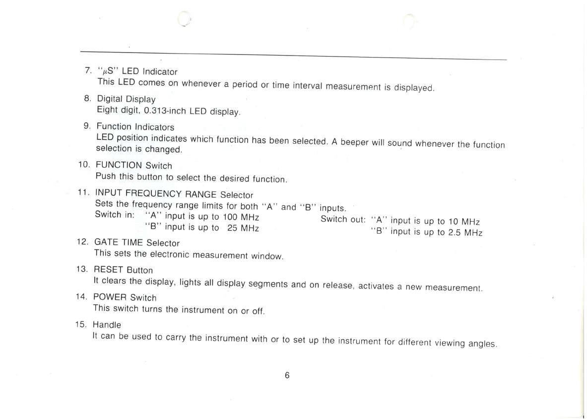
1' The maximum ¡nput voltage which can be applied to the input depends on the f requency of the input
and the position of the attenuator switch. This relationship is shown graphically in Figure 2, and the values
given in this figure must be strictly observed. To reduce the chancì of damáging ine inprt circuit, start
with the attenuator in the X 0.1 position. lf the counter doesnlt counl, then switch lhe allenuator to the
X 1 position.
2. Use this instrument within an ambient temperature range of OoC to S0oC. Do not place the counter on
top of high-temperature equipment.
3. Never permit water to enler the Interior of this instrument.
4. Never subject this instrument to severe shock,
2

Section Fou.
FEATURE DESCRIPTION
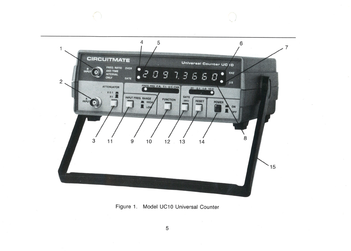
For features described in th¡s sect¡on, refer to Figure 1 lt is HIGHLY RECOI/MENDED that the user become
familiar with the controls, indicators. and connectors described below before operating the inslrument.
1. "B'' INPUT
Use this input only for Frequency Ratio and Time lnterval measurements.
2. ''4" INPUÏ
Use this input for Frequency, Period, Frequency Ratio. Time lnterval. and Unit Count measurements.
3. ATTENUATOR Switch
Pushing this switch in will provide a 10:.1 attenuation on the "A" input only. This feature w¡ll attenuate
high f requency noise components to prevent false triggering.
4. "OVER" LED lndicator
This LED will come on whenever the value of the display requires more than eight digits. When this
overflow condition exists, the display could be meaningless. lf the overflow condition happens in fre-
quency, period, frequency ratio. or time interval measurements, it can possibly be rectified by selecting
a smaller gate time, which in turn will decrease the number of decimal places so that a larger value
of eìght digits can be dìsplayed.
"GATE" LED lndicator
This LED will come on whenever the counter is counting or making a conversion. The length of time
that the LED is on is proportional to the gate time selected. This feature allows one to know whether
the electronic gate ¡s operating or not.
"KHZ" LED lndicator
This LED comes on whenever a frequency measurement is displayed.
Ã
4
67
15
Figure 1. Model UC10 Universal Counter
5
45
I
9 '10 12 13 14
3 11
l,- ,: 'i¡ -i :i ;:, ,g /r : ::
untvårrct Côuñúqr UC tC,
ctFtcut?t\dATE
,*å'dÌ1
\¿ ñåfo ilTto óvÊÂ
A¡O Tf,Ë
lNTråvÁL
fitY c¡E
2
7. "pS" LED lndicator
This LED comes on whenever a period or time intervar measurement is disprayed.
8. Digital Disptay
Eight digit, 0.313-inch LED disptay.
9. Function lndicators
LED position indicates which function has been selected. A beeper will sound whenever the function
selection is changed.
10. FUNCTTON Switch
Push this button to select the desired function.
11. INPUT FREQUENCY RANGE Se|ectoT
lels lhe frequency range limits for both ,,A" and ,,8,,inputs.
Switch in: "A" input is up to 100 MHz Switch out
,,8" Input is up to 25 MHz
12. GATE TIME Selector
This sets the electronic measurement w¡ndow.
13. RESET Button
It clears the display, lights all display segmenls and on release, activates a new measurement
14. POWER Swirch
This switch turns the instrument on or off
15. Handle
It can be used to carry the instrument with or to set up the instrument for different viewing angles
"4" input is up to 10 MHz
"8" input is up to 2.5 MHz
6

Section Five
BASIC MEASUREMENT INSTRUCTIONS
REMARKS
1. Observe maximum input voltage limits (see Figure 2).
2. When low frequencies are measured, a low pass
filter, as illustrated in Figure 3, can be inserted
between the signal ¡nput and the counter input to
attenuate high frequency components that may
cause false triggering.
3. For low frequency measurements see remark #2
under "Period."
1. Period (in seconds) is the inverse of frequency
(in Hz).
2. Period measurements may be used to determine low
ncy more quickly and accurate
1. Put the lower of the two input frequencies on
lnput B.
This feature operates with lnput A going low at the
start of the event, to be followed by lnput B going
low at the end of the event.
INPUT
CONNECTION
lnput A
lnput A
lnput A &
lnput B
lnput A &
lnput B
lnput A
None
GATE TIME
SETTING
Select
Select
Select
Select
N/A
N/A
RANGE
SETTING
LOW
HIGH
LOW
HIGH
LOW
HIGH
LOW
LOW
N/A
INPUT
MAGNITUDE
sHz to l0MHz
'10MHz to 100MHz
5Hz to 2.5MHz
2.5MHz to 25MHz
lnput A:
SHz to 1OMHz
lnput B:
5Hz to 2.5MHz
lnput A:
50Hz to 100MHz
lnput B:
50Hz to 25MHz
lnput A:
5Hz to 10MHz
lnput B:
5Hz to 2.5MHz
5Hz to 1OMHz
None
FUNCTION
Frequency
Period
Frequency
Ratio
Time
lnterval
Unit
Count
Check
7
INPUT VOLTAGE (Vpear)
212
't 50
100
'10
50
7
100 250 550 MHz
100K
0.001 uf
Figure 3. Low-Pass Filter
signal
source counter
input
75
0F
5Hz lKHz 50 100 KHz 1 MHz
NOTE: These values must not be exceeded when the s¡gnal
contains a DC component (VÞeak = DC Voltage + Peak AC Voltage).
When there is no DC component, Vpeak = Peak AC Voltage.
Figure 2. Maximum lnput Voltage versus Frequency
8
Section Six
SPECIFICATIONS
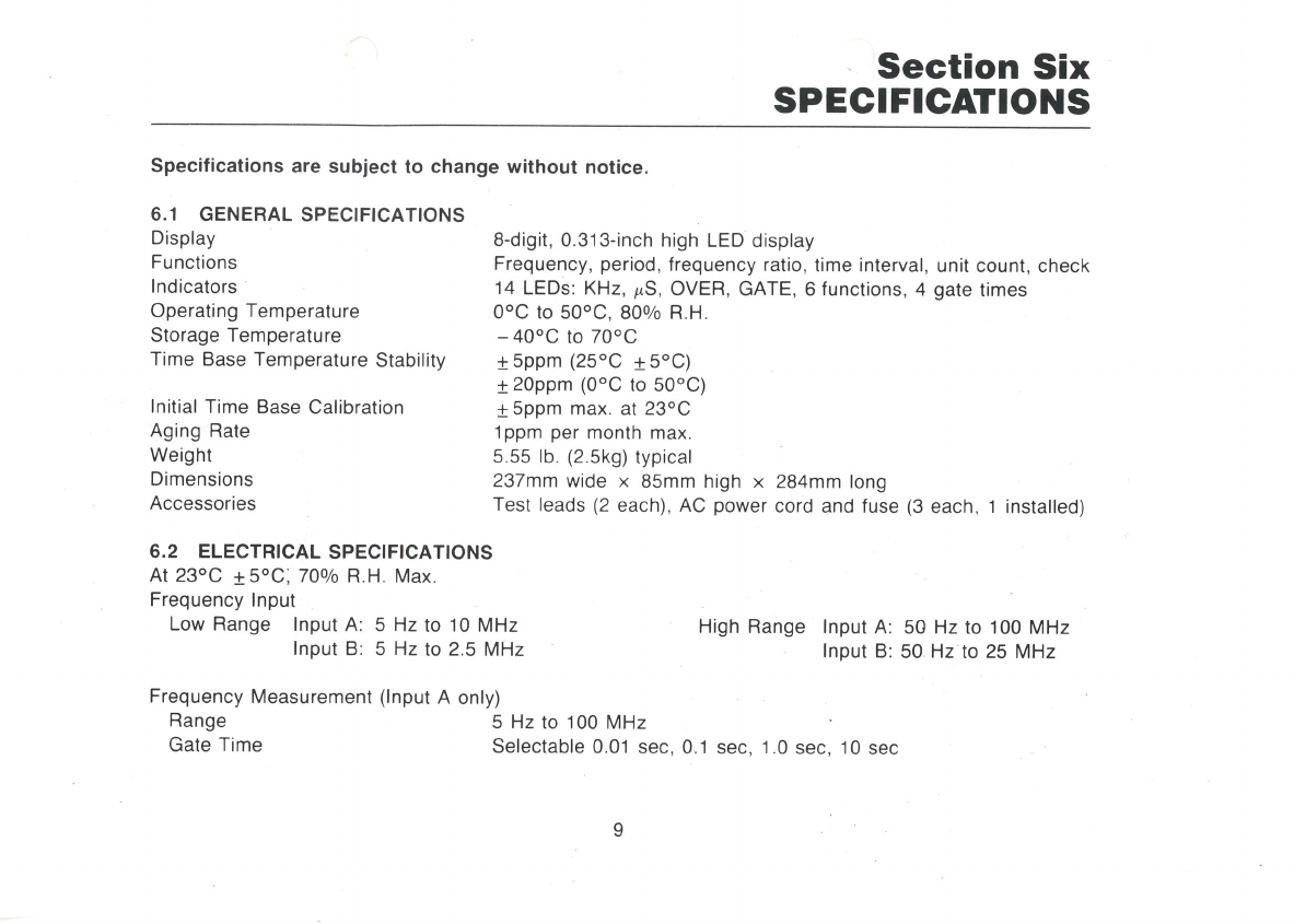
Specifications are subject to change without notice
6.1 GENERAL SPECIFICATIONS
Display
Functions
lndicators
Operating Temperature
Storage Temperature
Time Base Temperature Stability
lnitial Time Base Calibration
Aging Rate
Weight
Dimensions
Accessories
6.2 ELECTRICAL SPECIFICATIONS
At 23oC tSoC',70o/o R.H. Max.
Frequency lnput
Low Range lnput A: 5 Hz to 10 MHz
lnput B: 5 Hz to 2.5 MHz
8-digit, 0,313-inch high LED display
Frequency, period, frequency ratio, t¡me interval, unit count, check
'1 4 LEDs: KHz, ¡rS, OVER, GATE, 6 functions, 4 gate times
0"C to 50oC, 800/o R.H.
-40oC to 70oC
+Sppm (25'C t5'C)
t20ppm (0'C to 50'C)
fSppm max. at 23oC
lppm per month max.
s.55 lb. (2.5k9) typical
237mm wide x 85mm high x 284mm long
Test leads (2 each), AC power cord and fuse (3 each, 1 installed)
High Range lnput A: 50 Hz to 100 MHz
lnput B: 50 Hz to 25 MHz
Frequency Measurement (lnput A only)
Range 5 Hz to 100 MHz
Gate Time Selectable 0.01 sec, 0.1 sec, 1.0 sec, 10 sec
I

Frequency Measurement (lnput A only) (Continued)
Résolution
5 Hz to 10 MHz 100 Hz, 10 Hz, 1 Hz,O.'l Hz
50 Hz to 100 MHz 1000 Hz, 100 Hz, '10 Hz,1 Hz
Accuracy I (Time base stability + 1 count)
Period Measurement (lnput A only)
Range 0.04 ¡rsec to 0.2 sec
Gate Time Selectable 0.01 sec, 0.1 sec, 1.0 sec, 10 sec
Resolution
5 Hz to 2.5MHz 0.1 nsec, 1.0 nsec, 10 nsec, 100 nsec
2.5 MHz to 25 MHz 0.01 nsec, 0.1 nsec, 1.0 nsec, 10 nsec
Accuracy I 1 count l time base stability + trigger error of signal
Frequency Ratio (lnput A + lnput B)
lnput Frequency
Low Range lnput A: 5 Hz to 10 MHz High Range lnput A: 50 Hz to 100 MHz
lnput B: 5 Hz to 2.5 MHz lnput B: 50 Hz to 25 MHz
Acccuracy + 1 count of input A + trigger error of input B
Time lnterval (lnput A to lnput B)
lnput Frequency 5 Hz to 2.5 MHz
(Low Range only)
Range 0.4 psec to 0.2 sec
Gate time Selectable 0.01 sec, 0.'l sec, 1.0 sec, 10 sec
Resolution 100 nsec, 10 nsec, 1,0 nsec, 0.1 nsec
Accuracy 11 count ltime base accuracy ltrigger error
10
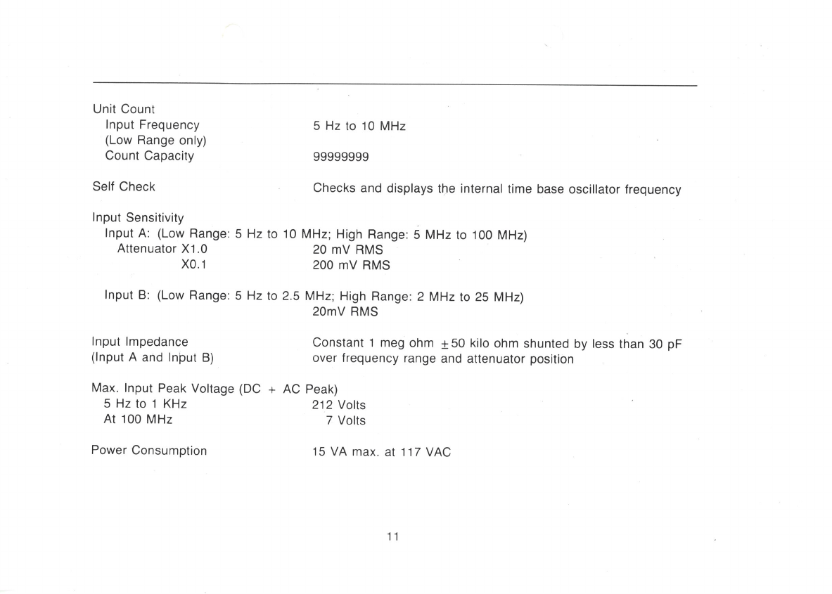
Self Check Checks and displays the internal time base oscillator frequency
lnput Sensitivity
lnput A: (Low Range: 5 Hz to 10 MHz; High Range:5 MHz to 100 MHz)
Attenuator X1.0 20 mV RMS
X0.1 200 mV RMS
lnput B: (Low Range: 5 Hz to 2.5MHz; High Range: ZMHz to 25 MHz)
20mV RMS
lnput lmpedance Constant 1 meg ohm t50 kilo ohm shunted by less than 30 pF
(lnput A and lnþut B) over frequency range and attenuator position
Max. lnput Peak Voltage (DC + AC Peak)
Unit Count
lnput Frequency
(Low Range only)
Count Capacity
5Hztol KHz
At 100 MHz
Power Consumption
5 Hz to 10 MHz
99999999
212 Volts
7 Volts
15 VA max. at 117 VAC
11
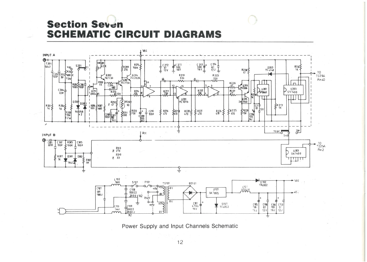
Section Serr.rn
SCHEMATIC CIRCUIT DIAGRAMS
\tc
INPIJ I A
INPUI B
l0
7226A
Pn 10
TO
.12214
RJOS t 105
r00P nt'3
710
Rlro
l:
.x
)l
P¡n 2
F 10r TS101 B!1 OI
Power Supply and lnput Channels Schematic
UT!
sN?100
u203
sr ?¿00
211
1K
t
R2Tt
¡?0 P2L
(l
UðI
't(10f6
R?20,
¿70 :
1ÎF
R?ró
¿t0
Rll
RA2
19
90
0
12

____Q8 D7 06 D5 D¿ D3 D2 ù
PUT
IN
IN Ia.
D
c.
0
'Ý
hr
+5v
220
t_ I t_t t_t t_ t
t_
I
I
PUT t_
t_
t_
t_
t_
tt
t_
cso3 0,0017
10K
:REO
PRD
F. R.
-r. l.
u.c.
CiTK
0.ì sec
r0 sel
FO
F1
F2
'Fi
GO
,2
..^:
'.,5C GN D
¿011 1L 1
LAl .7 '5 8.:?
¿066 :: 1
1.10¿ ': '¡
Counter and Control Log¡c Schematic
tcL'7226A
D1
n,
D3
A
IN
u4c2
L-- _
L
c1l1
o1
12V
niä;
l0K
u50?¿066
u508 ¿06 6
u51C -.1úó
u509 1066
r¡',
u5r1 ¿066
u503 ¿01?
u50¿ 7¿0¿
U506 7¿,0¿
u505 ¿017
usl 1clt
---..]
u502 {,011
13
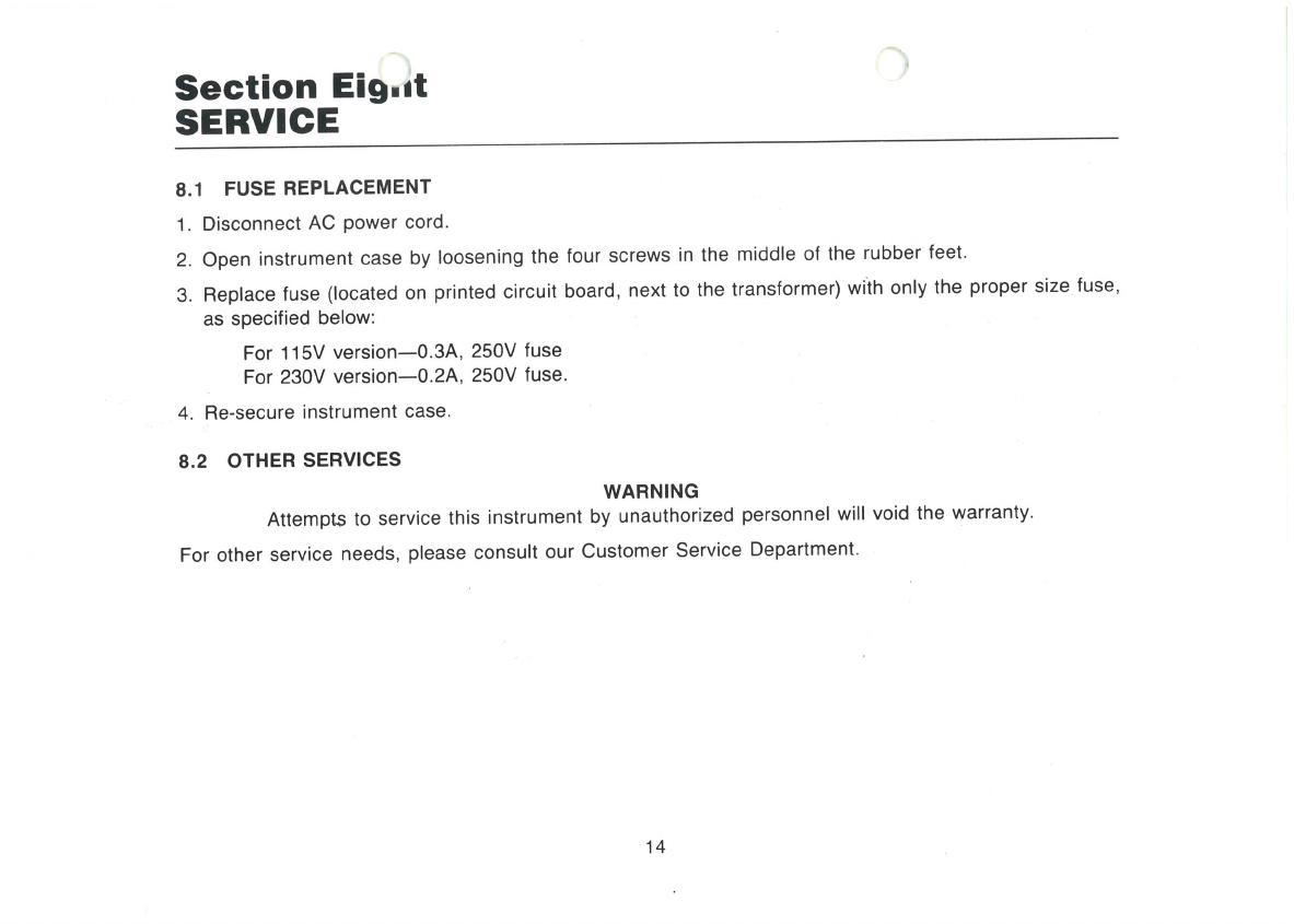
Section Eig'it
SERVICE
8.1 FUSE REPLACEMENT
1. Disconnect AC Power cord.
2. Open instrument case by loosening the four screws in the middle of the rubber feet'
3. Replace fuse (located on printed circuit board, next to the transformer) wiìh only the proper size fuse,
as specified below:
For 115V version-0.34,250V fuse
For 230V version-0.24, 250V fuse'
4. Re-secure instrument case.
8.2 OTHER SERVICES WARNING
Attempts to service this instrument by unauthorized personnel will void the warranty
For other service needs, please consult our customer service Department.
14
Table of contents
Popular Cash Counter manuals by other brands


ipf electronic
ipf electronic VY200120 quick start guide

HP
HP 5245L Service manual

Cassida
Cassida C-880 user manual

ipf electronic
ipf electronic CM03 5 Series manual

Nautilus Hyosung
Nautilus Hyosung MX5300CE Operator's manual

MC Electronics
MC Electronics AREA CONTROL MCK 3000 Use and Assembly Instructions


