MC Electronics AREA CONTROL MCK 3000 User manual

AREA CONTROL MCK 3000
UNIVERSAL HECTARE COUNTER
FOR AGRICULTURAL MACHINERY
USE AND ASSEMBLY
INSTRUCTIONS
NO.201211MI
REV. 2
EN

MCK 3000
Installation and use
MCK 3000
This product complies with the EMC requirements as defined by Directives
2004/108/EC and subsequent amendments
and refers to the applied Standard EN ISO 14982
Manufacture
r
: MC elettronica S.r.l.
Address
: Via E. Fermi, 450/486
Fiesso Umbertiano (ROVIGO) - ITALY
Tel. +39 0425 754713 Fax +39 0425 741130
E-mail: [email protected]
Internet: www.mcelettronica.it
Manual code
: 201211MI
Issued
: July 2012
Edition
: November 2020
MC elettronica S.r.l. is not obliged to give notice of any further modifications of the product.
The information given in this manual does not allow unauthorized personnel to tamper with the
product in any way.
The warranty on the equipment will no longer be valid if tampering should be detected.
© Copyright MC elettronica 2020

Installation and use 3
MCK 3000
Contents
1. Rules and general warnings ................................................................................ 4
1.1 Introduction....................................................................................................... 4
1.2 Terms of the warranty....................................................................................... 5
1.3 Service.............................................................................................................. 5
2. General description .............................................................................................. 6
3. System installation............................................................................................... 7
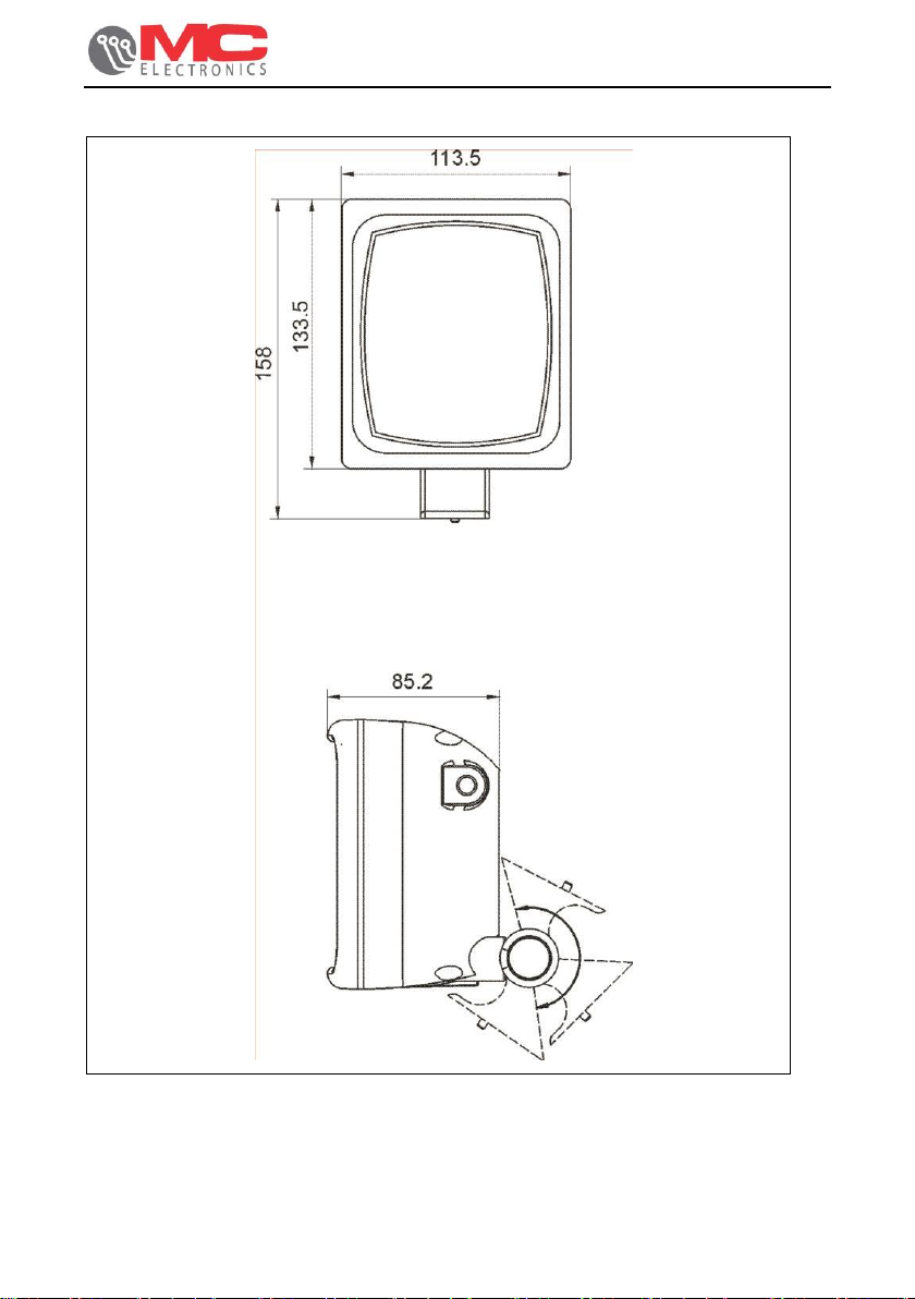
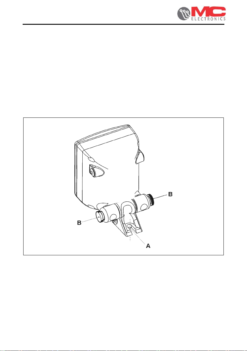
3.1 Mounting the Monitor ........................................................................................ 8
3.2 Sensor installation............................................................................................. 9
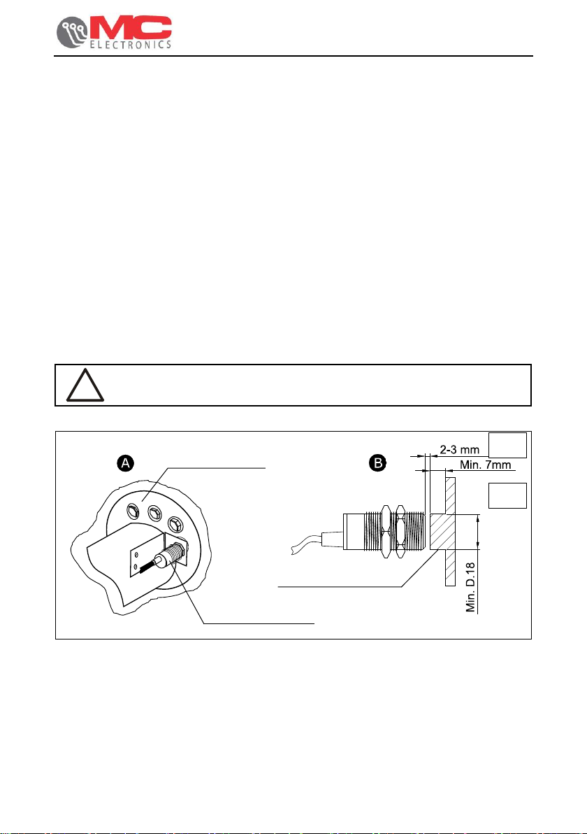
3.2.1 Speed sensor installation........................................................................... 9
3.2.1.1 Automatic calibration of the “C” parameter ......................................... 10
3.2.2 Installing the mechanical counting sensor (if present) ............................. 11
3.2.3 Installing the reflection seed sensor (if present)....................................... 12
3.2.3.1 Adjusting the sensitivity of the seed sensor ........................................ 13
3.3 Front view ....................................................................................................... 14
3.3.1 Keyboard.................................................................................................. 15
3.3.2 LCD Display............................................................................................. 16
4. Accessories......................................................................................................... 16
4.1 Standard accessories...................................................................................... 16
5. Setting the work parameters.............................................................................. 17
5.1 Setting the working width................................................................................ 17
5.2 Setting the calibration of the feed-rate ............................................................ 17
5.3 Setting the number of divisions of the total width............................................ 18
5.4 Setting the hectare count mode ...................................................................... 18
5.5 Programming the date/clock (if present) ......................................................... 19
5.6 Check the speed sensor operating ................................................................. 20
5.7 Check that the mechanical counting sensor functions .................................... 20
5.8 Check that the seed sensor functions (if present)........................................... 20
6. Operation............................................................................................................. 21
7. Maintenance........................................................................................................ 23
7.1 Routine maintenance...................................................................................... 23
7.1.1 How to protect the main connector .......................................................... 23
7.2 Extraordinary maintenance............................................................................. 23
8. Troubleshooting.................................................................................................. 24
9. Technical data..................................................................................................... 25
9.1 MCK 3000 Area Control Technical data.......................................................... 25
9.2 Accessory technical data ................................................................................ 25
9.2.1 MC speed inductive sensor –code 481................................................... 25

MCK 3000
Installation and use
MCK 3000
1. Rules and general warnings
1.1 Introduction
This instruction manual provides all specific information needed to know and correctly
use the equipment.
After buying the Monitor, read the manual carefully and refer to it any time you have
doubts on how to use the equipment or when you have to carry out maintenance
operations.
The manual must be kept on the machine or at least, when this is not possible, it
must be kept in a known place that is accessible for easy reference.
ALL RIGHTS RESERVED. THIS MANUAL IS INTENDED FOR CUSTOMERS ONLY. ANY
OTHER USE ISFORBIDDEN.

Installation and use 5
MCK 3000
1.2 Terms of the warranty
•SUBJECT OF THE WARRANTY: the warranty is applied to the product and to
those parts which are marked with the serial number or any other identification
number used by MC elettronica;
•DURATION OF THE WARRANTY: MC elettronica S.r.l. guarantees the MCK
3000 Monitor for a period of 1 year from the date of manufacture (printed on the
identification label on the rear of the monitor) and the accessories for a period of
1 year.
The warranty covers the product and any repairs carried out within the agreed
terms.
This warranty does not apply in the event of:
•accidental damage;
•improper use;
•changes which have not been agreed upon, improper installation (or set-up);
•damage caused when equipment not manufactured by MC elettronica,
which is mechanically or electrically connected to our instruments, breaks or
does not function properly;
•force majeure events (lightning, floods, fire or other causes which do not
depend on MC elettronica).
Repairs under warranty, which must be carried out in the laboratories of our
authorised centres, are entirely free of charge provided the equipment is directly
transported to said laboratories or sent carriage free. Transport costs and
ensuing risks are entirely borne by the Customer.
The above-mentioned warranty is valid unless otherwise agreed between MC
elettronica and the Customer.
!
Warning
MC elettronica declines any liability for damage or direct or indirect costs
caused by improper use or inability of the Customer to use the
equipment separately and/or together with other equipment.
1.3 Service
Service is available in all the countries where the Computer is officially supplied by
MC elettronica (during and after the warranty period).
Any kind of operation that is to be carried out on the MCK 3000 Monitor must be
done in accordance with the instructions stated in this manual or as agreed with MC
elettronica.
If not, the relative terms of the warranty might become null and void.

MCK 3000
Installation and use
MCK 3000
2. General description
The MCK 3000 Control Area is a universal hectare counter that can be installed on
any type of agricultural machine. With this instrument the following parameters can
be monitored:
•partial worked area;
•total worked area;
•distance travelled;
•speed (Km/h);
•forecast of the hectares that will be worked in an hour (only visible while you are
working).
The Monitor uses a speed sensor to carry out the functions described above, which is
to be installed on the machine wheel, and a mechanical counting sensor or a seed
sensor.
Figure 1. Example of application on standard combine harvester.
Mechanical
counting
sensor
Battery
Speed
sensor
Monitor

Installation and use 7
MCK 3000
3. System installation
Figure 2. Overall dimensions

MCK 3000
Installation and use
MCK 3000
3.1 Mounting the Monitor
To assemble the instrument operate as follows:
•on a flat surface inside the cabin of the vehicle, drill 2 holes (D. 9 mm)
aligned with those on the bracket (Figure 33 - ref. <A>) and, by means of
two screws (not supplied), securely fasten the bracket to the structure;
•fasten the Monitor to the bracket by screwing the supplied knobs (Figure 33
- ref. <B>) in the holes on the sides of the Monitor (Figure 33 - ref. <B1>).
N.B.:
we recommend installing the Monitor in front of the operator to make it
easier to use during the working cycle.
Figure 3. How to assemble the Computer.

Installation and use 9
MCK 3000
3.2 Sensor installation
The MCK 3000 Area Control can be equipped with 3 types of sensors:
•speed sensor (always present);
•mechanical counting sensor (for NON self-levelling combine harvesters, tractors,
etc.);
•reflection seed sensor (for self-levelling combine harvesters).
3.2.1 Speed sensor installation
You can install the speed sensor anywhere there is mechanical movement, on the
wheel (front or rear) of the agricultural machine/vehicle or by creating a metal
reference protruding by at least 7 mm ( Figure 4 ref. B2). We recommend installing
the speed sensor inside the wheel and placing the sensor head opposite the rim bolts
(Figure 4 –ref. A and B).
Set the gap between the sensor and the bolts at about 2/3 mm (Figure 4 –ref. B1).
Firmly fix the sensor bracket (supplied) to a secure part of the machine. Fix the
sensor to the bracket with the nut and the lock nut.
!
Warning
The sensor cable should be covered with a rubber sheath.
Figure 4. How to install the speed sensor.
Inner side of wheel
Speed sensor
Metal reference
B2
B1

MCK 3000
Installation and use
MCK 3000
3.2.1.1 Automatic calibration of the “C” parameter
Parameter “C” is automatically set by covering a fixed distance of 100 metres,
according to the following procedure:
▪With the Monitor on, press the key several times until the arrow on the
display lights up as shown in the figure: ;
▪press keys and simultaneously: 0 0 will appear on the Monitor;
•cover 100 metres and the display will show the pulse count (1..2..3, etc.); once
the 100 metres are covered, confirm with the key.
N.B.: it is recommended to perform the operation at least 2 times in a row, checking
that the detected value is always the same 1 pulse. If the difference is
greater, it means that the speed sensor is NOT positioned correctly.
Therefore, the assembly must be checked (see Figure 4)

Installation and use 11
MCK 3000
3.2.2 Installing the mechanical counting sensor (if present)
The mechanical counting sensor is used if the monitor is installed on a standard
combine harvester. It can be secured to the lower part of the bar so that when this
lowers, the spring is released and the hectare count begins (parameter “Ct” = A, as
factory-set) (see Figure 5 –ref. A2).
!
Attention!
Adjust the trip point of the switch by changing the number of links in the
chain.
Figure 5. Installing the sensor in the lower part of the bar.
If necessary, the switch can also be secured to the upper part of the bar, by setting
parameter “Ct” = C (see chapter 5, “Programming work parameters”). This way, when
the bar is lowered, the spring is tensioned, and the hectare count begins (see Figure
6 –ref. B2).
Figure 6. Installing the sensor in the upper part of the bar.
!
Warning
The sensor cable should be covered with a rubber sheath.
Bar
Bar
Counting
sensor
Counting
sensor
Raised bar
Lowered bar
Counting
sensor
Counting
sensor

MCK 3000
Installation and use
MCK 3000
3.2.3 Installing the reflection seed sensor (if present)
The seed sensor is used if the monitor is installed on a self-levelling combine
harvester.
Secure the seed sensor in a stable way on the right or left side of the pipe, using the
bracket (supplied) with the lens facing the ground, and the optical axis perpendicular
to the ground, at a distance of no more than 1.10 metre (see Figure 7).
!
Warning
The sensor cable should be covered with a rubber sheath.
Figure 7. Installing the seed sensor.
Seed sensor optical beam
Seed sensor
MAX.
distance
1.10 m

Installation and use 13
MCK 3000
3.2.3.1 Adjusting the sensitivity of the seed sensor
After installing the seed sensor, proceed as follows to adjust its sensitivity:
1. Check that the sensitivity
adjustment trimmer (A) is turned to
the extreme hourly position;
2. Turn the monitor on. The RED LED
(B) must be on; otherwise,
enhance the orientation or move
the seed sensor closer.
3. Turn the trimmer (A) very slowly
clockwise until the LED (B) turns
off.
4. Turn the trimmer (A) again
clockwise by a few tenths of a
degree for optimal adjustment.
SEED SENSOR
LED
on
LED
off
far
right
SEED SENSOR
LED
off
final
position
SEED SENSOR

MCK 3000
Installation and use
MCK 3000
3.3 Front view
Figure 8. Front view.
The front panel allows the user to view all the data relating to the working cycle. The
following elements can be seen on the panel:
REF.
DESCRIPTION
A.
ON/OFF key
B.
LCD Display
C.
Programming key
D.
<+> and <-> keys
E.
Forward speed/forecast of workable hectares/distance covered display key
F.
Totally/partially worked area display key
G.
Work width splitting key
A
B
D
C
G
F
E

Installation and use 15
MCK 3000
3.3.1 Keyboard
KEY
FUNCTION
During the programming phase the operator can increase the value of
the data by one figure at a time (by pressing and holding the key, the
values displayed can be altered more quickly).
During the programming phase the operator can decrease the value of
the data by one figure at a time (by pressing and holding the key, the
values displayed can be altered more quickly).
Programming key:
allows you to set the parameter selected at that moment (using the
and keys) by the indicator arrow:
▪total work width;
▪calibration of the feed-rate;
▪number of sectors in which to split the bar.
Display key:
allows you to view the parameter selected at that moment by the
indicator arrow:
▪feed-rate;
▪forecast of the hectares that can be worked in an hour (only if speed
is present);
▪distance covered (in metres).
Display key:
allows you to view the parameter selected at that moment by the
indicator arrow:
▪total worked area;
▪partial worked area.
Key to split the working width and select the MANUAL mode.
ON/OFF key.
The key can be used to switch the instrument on and off.

MCK 3000
Installation and use
MCK 3000
3.3.2 LCD Display
REF.
DESCRIPTION
1
Indicator bars: allow you to view the number of sectors in which the
programmed working width can be split
2
6-digit display: constantly displays the required parameters by the keys
3
Indicator arrows: indicate the function selected for every key
,and
4. Accessories
4.1 Standard accessories
Table 4-1. Standard accessories
CODE
DESCRIPTION
PF0481
Speed sensor D. 18/5 with bracket
PF0484
Mechanical counting spring sensor
PF1084
Seed counting sensor
PF0489
Standard wiring harness for speed sensor and counting
sensor
PF0488
Simple wiring harness for speed sensor

Installation and use 17
MCK 3000
5. Setting the work parameters
5.1 Setting the working width
Set the total working width “M” by turning the instrument on ( key) and pressing
the key several times until the first arrow on the left on the display lights up.
Settable range
: 0.10 40.00
step
: 0.01
default
: 5.00
Press and to change the parameter.
Once the desired value has been reached, release the keys and wait <3> seconds to
allow the new parameter that has just been entered to be saved.
5.2 Setting the calibration of the feed-rate
Set the calibration of the feed-rate “C” (number of pulses coming from the speed
sensor every 100 metres covered by the machine), by turning the instrument on
( key) and pressing the key several times until the second arrow on the
left on the display lights up.
Settable range
: 50 999
step
: 1
default
: 200
Press and to change the parameter.
Once the desired value has been reached, release the keys and wait <3> seconds to
allow the new parameter that has just been entered to be saved.
N.B. it is recommended to calibrate this parameter automatically (see paragraph
3.2.1.1, “Automatic calibration of parameter C””).

MCK 3000
Installation and use
MCK 3000
5.3 Setting the number of divisions of the total width
Set the number of divisions of the total width “N” by turning the instrument on (
key) and pressing the key several times until the third arrow on the left on
the display lights up.
Settable range
: 2 10
step
: 1
default
: 2
Press and to change the parameter.
Once the desired value has been reached, release the keys and wait <3> seconds to
allow the new parameter that has just been entered to be saved.
When the parameter has been saved, the bars in the top part of the display will light
up to show the number of set divisions.
5.4 Setting the hectare count mode
Set the hectare count mode by turning the instrument on ( key) and simultaneously
pressing the and keys until parameter “Ct” appears on the display
followed by a message indicating when the monitor will count the area.
The count mode can be changed with the and keys; consider the type of
isolator used when setting it: either a simple switch that opens and closes a contact
(count magnetic sensor), or an electronic signal (seed sensor).
You can set:
Ct = A
: the Monitor will only count the area when the contact that acts as an isolator
will be OPEN;
Ct = C
: the Monitor will only count the area when the contact that acts as an isolator
will be CLOSED;
Ct = FA
: the Monitor will only count the area when the seed sensor will emit the
“free” signal (no objects in front of the lens);
Ct = FC
: the Monitor will only count the area when the seed sensor will emit the
“blocked” signal (objects in front of the lens).

Installation and use 19
MCK 3000
5.5 Programming the date/clock (if present)
Program the date and the clock by turning the monitor on ( key)
by holding down the key for <3> seconds until the first data appears
“Yr”.
DATA
PROGRAMMING
Current year:
Settable range
: 00 99
step
:1
default
: 00
Press to confirm the data.
Current month:
Settable range
: 0112
step
:1
default
: 01
Press to confirm the data.
Current day:
Settable range
: 01 31
step
:1
default
: 01
Press to confirm the data.
Current hour:
Settable range
: 00 23
step
:1
default
: 00
Press to confirm the data.
Current minute:
Settable range
: 00 59
step
:1
default
: 00
Press to confirm the data.

MCK 3000
Installation and use
MCK 3000
5.6 Check the speed sensor operating
Check the functioning of the speed sensor as follows:
1. Turn the monitor on ( key);
2. Repeatedly pass in front of the red part of the sensor using a screwdriver or
other metal mass. If the computer displays the simulated speed (which probably
will not be constant) it means that the sensor is functioning and is properly
connected.
5.7 Check that the mechanical counting sensor functions
Check the operation of the mechanical sensor as follows:
1. Turn the monitor on ( key);
2. Select the partial/total hectare display ( key);
3. Pull the sensor chain so as to close the contact (or vice versa, depending on the
mechanical position);
4. Check that the display flashes when you do not want the area to be increased.
5.8 Check that the seed sensor functions (if present)
Check the operation of the photocells as follows:
1. Turn the monitor on ( key);
2. Use the hydraulic controls on the machine to raise and lower the bar, making
sure that the display flashes when the counting is stopped (raised bar).
Table of contents
Other MC Electronics Cash Counter manuals