Beckoff CX9020 User manual
Manual
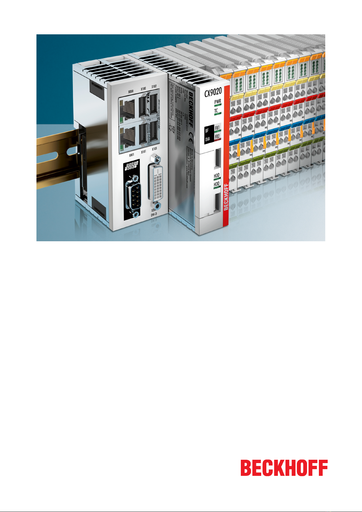
CX9020
Embedded PC
2.0
2019-04-09
Version:
Date:


Table of contents
CX9020 3Version: 2.0
Table of contents
1 Notes on the documentation ....................................................................................................................5
1.1 Explanation of symbols......................................................................................................................6
1.2 Related documents............................................................................................................................7
1.3 Documentation issue status ..............................................................................................................7
2 For your safety...........................................................................................................................................8
2.1 Intended use......................................................................................................................................8
2.2 Staff qualification ...............................................................................................................................9
2.3 Safety instructions .............................................................................................................................9
3 Transport and storage.............................................................................................................................11
4 Product overview.....................................................................................................................................12
4.1 Structure of the CX9020 Embedded PC..........................................................................................13
4.2 Name plate ......................................................................................................................................14
4.3 Types...............................................................................................................................................15
4.4 Architecture overview ......................................................................................................................16
5 Description of the interfaces ..................................................................................................................17
5.1 USB (X100, X101, X102, X103) ......................................................................................................17
5.2 Ethernet RJ45 (X000, X001) ...........................................................................................................18
5.3 DVI-D (X200) ...................................................................................................................................19
5.4 Optional interfaces...........................................................................................................................20
5.4.1 Audio interface (N020)..................................................................................................... 20
5.4.2 RS232 (N030).................................................................................................................. 21
5.4.3 RS422/RS485 (N031)...................................................................................................... 22
5.4.4 EtherCAT slave (B110).................................................................................................... 23
5.4.5 PROFIBUS (x310) ........................................................................................................... 24
5.4.6 CANopen (x510) .............................................................................................................. 25
5.4.7 PROFINET RT (x930)...................................................................................................... 26
6 Commissioning........................................................................................................................................27
6.1 Assembly .........................................................................................................................................27
6.1.1 Note the permissible installation positions ...................................................................... 27
6.1.2 Attaching on mounting rail ............................................................................................... 29
6.1.3 MicroSD card installation and removal ............................................................................ 30
6.1.4 Installing passive EtherCAT Terminals............................................................................ 31
6.2 Connecting the power supply ..........................................................................................................32
6.3 Switching on ....................................................................................................................................34
6.4 Switching off ....................................................................................................................................34
7 Configuration ...........................................................................................................................................35
7.1 Windows Embedded Compact 7 .....................................................................................................35
7.1.1 Setting up the audio interface (N020) .............................................................................. 35
7.2 Beckhoff Device Manager ...............................................................................................................36
7.2.1 Starting the Beckhoff Device Manager ............................................................................ 36
7.2.2 Enabling a remote display ............................................................................................... 37
7.3 TwinCAT..........................................................................................................................................38
7.3.1 Tree view ......................................................................................................................... 38

Table of contents
CX90204 Version: 2.0
7.3.2 Searching for target systems ........................................................................................... 39
7.3.3 Adding an Embedded PC ................................................................................................ 41
8 NOVRAM...................................................................................................................................................42
8.1 Use under TwinCAT 3 .....................................................................................................................43
8.1.1 Creating a Retain Handler ............................................................................................... 43
8.1.2 Creating and linking variables.......................................................................................... 45
8.1.3 Note the write speed of the Retain Handler..................................................................... 47
8.1.4 Deleting variables under the Retain Handler ................................................................... 48
9 1-second UPS (persistent data)..............................................................................................................49
9.1 FB_S_UPS_CX9020_U900.............................................................................................................50
9.2 Mode and status of the function block .............................................................................................52
9.3 Checking the validity of the variables ..............................................................................................53
9.3.1 SYSTEMINFOTYPE ........................................................................................................ 53
9.3.2 PlcAppSystemInfo ........................................................................................................... 55
10 Error handling and diagnostics..............................................................................................................56
10.1 Diagnostic LEDs ..............................................................................................................................56
10.2 Power supply terminal LEDs in K-bus mode ...................................................................................57
10.3 Power supply terminal LEDs in E-bus mode ...................................................................................60
10.4 Faults...............................................................................................................................................61
11 Care and maintenance ...........................................................................................................................62
11.1 Replace the battery .........................................................................................................................62
12 Decommissioning....................................................................................................................................63
12.1 Removing cables .............................................................................................................................63
12.2 Dismantling the Embedded PC .......................................................................................................64
13 Technical data..........................................................................................................................................65
14 Appendix ..................................................................................................................................................67
14.1 Accessories .....................................................................................................................................67
14.2 Certifications....................................................................................................................................68
14.3 Support and Service ........................................................................................................................69
List of tables.............................................................................................................................................70
List of figures...........................................................................................................................................71

Notes on the documentation
CX9020 5Version: 2.0
1 Notes on the documentation
This description is only intended for the use of trained specialists in control and automation engineering who
are familiar with the applicable national standards.
It is essential that the documentation and the following notes and explanations are followed when installing
and commissioning the components.
It is the duty of the technical personnel to use the documentation published at the respective time of each
installation and commissioning.
The responsible staff must ensure that the application or use of the products described satisfy all the
requirements for safety, including all the relevant laws, regulations, guidelines and standards.
Disclaimer
The documentation has been prepared with care. The products described are, however, constantly under
development.
We reserve the right to revise and change the documentation at any time and without prior announcement.
No claims for the modification of products that have already been supplied may be made on the basis of the
data, diagrams and descriptions in this documentation.
Trademarks
Beckhoff®, TwinCAT®, EtherCAT®, Safety over EtherCAT®, TwinSAFE®, XFC® and XTS® are registered
trademarks of and licensed by Beckhoff Automation GmbH.
Other designations used in this publication may be trademarks whose use by third parties for their own
purposes could violate the rights of the owners.
Patent Pending
The EtherCAT Technology is covered, including but not limited to the following patent applications and
patents:
EP1590927, EP1789857, DE102004044764, DE102007017835
with corresponding applications or registrations in various other countries.
The TwinCAT Technology is covered, including but not limited to the following patent applications and
patents:
EP0851348, US6167425 with corresponding applications or registrations in various other countries.
EtherCAT® is registered trademark and patented technology, licensed by Beckhoff Automation GmbH,
Germany
Copyright
© Beckhoff Automation GmbH & Co. KG, Germany.
The reproduction, distribution and utilization of this document as well as the communication of its contents to
others without express authorization are prohibited.
Offenders will be held liable for the payment of damages. All rights reserved in the event of the grant of a
patent, utility model or design.
Table of contents
Popular Industrial PC manuals by other brands


Dell
Dell Embedded Box PC 5000 Installation and operation manual

IBASE Technology
IBASE Technology ASB200-918 Series user manual

Lenovo
Lenovo ThinkCentre M90q Hardware Maintenance Manual

IXXAT
IXXAT Econ 100 Hardware manual

Kontron
Kontron KBox A-151-TGL user guide

AXIOMTEK
AXIOMTEK ICO500-518 Series user manual