Stackrack THOR200 User manual

WWW.STACKRACK.COM
Version 1.
0
Revision Date:
July
. 0
5
, 2017
MIL-STD Rugged Computer
User's Manual
THOR200
MIL-STD Rugged Computer

WWW.STACKRACK.COM
Version 1.
0
Revision Date:
July
. 0
5
, 2017
MIL-STD Rugged Computer
User's Manual
Safety information
Electrical safety
To prevent electrical shock hazard, disconnect the power cable from the electrical outlet before
relocating the system.
When adding or removing devices to or from the system, ensure that the power cables for the
devices are unplugged before the signal cables are connected. If possible, disconnect all power cables
from the existing system before you add a device.
Before connecting or removing signal cables from the motherboard, ensure that all power cables are
unplugged.
Seek professional assistance before using an adapter or extension cord. These devices could interrupt
the grounding circuit.
Make sure that your power supply is set to the correct voltage in your area.
If you are not sure about the voltage of the electrical outlet you are using, contact your local power
company.
If the power supply is broken, do not try to fix it by yourself. Contact a qualified service technician or
your local distributor.
Operation safety
Before installing the motherboard and adding devices on it, carefully read all the manuals that came
with the package.
Before using the product, make sure all cables are correctly connected and the power cables are not
damaged. If you detect any damage, contact your dealer immediately.
To avoid short circuits, keep paper clips, screws, and staples away from connectors, slots, sockets and
circuitry.
Avoid dust, humidity, and temperature extremes. Do not place the product in any area where it may
become wet.
Place the product on a stable surface.
If you encounter any technical problems with the product, contact your local distributor
Statement
All rights reserved. No part of this publication may be reproduced in any form or by any means,
without prior written permission from the publisher.
All trademarks are the properties of the respective owners.
All product specifications are subject to change without prior notice
1

WWW.STACKRACK.COM
Version 1.
0
Revision Date:
July
. 0
5
, 2017
MIL-STD Rugged Computer
User's Manual
Revision History
Revision
Date (yyyy/mm/dd)
Changes
V1.0
2017/07/05
Initial release
Packing list
□THOR200 MIL-STD Rugged Computer
□XR-DIMM up to 16 GB RAM optional
Accessories Kit
□Cable Kits optional
□CD (Driver + User’s Manual)
If any of the above items is damaged or missing, please contact your local distributor.
Ordering information
Model Number
Description
THOR200
Intel® Broadwell MILSTD IP65 Rugged System with Core™ i7-5650U Processor,
NVIDIA GT730M GPU, Amphenol M12 Connectors,
9V to 36V DC-in, Wide Temp. -40 to 70°C
2

WWW.STACKRACK.COM
Version 1.
0
Revision Date:
July
. 0
5
, 2017
MIL-STD Rugged Computer
User's Manual
Table of contents
SAFETY INFORMATION ........................................................................................................................................ 1
ELECTRICAL SAFETY..................................................................................................................................................... 1
OPERATION SAFETY .................................................................................................................................................... 1
STATEMENT......................................................................................................................................................... 1
REVISION HISTORY .............................................................................................................................................. 2
PACKING LIST ...................................................................................................................................................... 2
ACCESSORIES KIT................................................................................................................................................. 2
ORDERING INFORMATION................................................................................................................................... 2
TABLE OF CONTENTS........................................................................................................................................... 3
CHAPTER 1: PRODUCT INTRODUCTION............................................................................................................... 5
1.1 KEY FEATURES ..................................................................................................................................................... 5
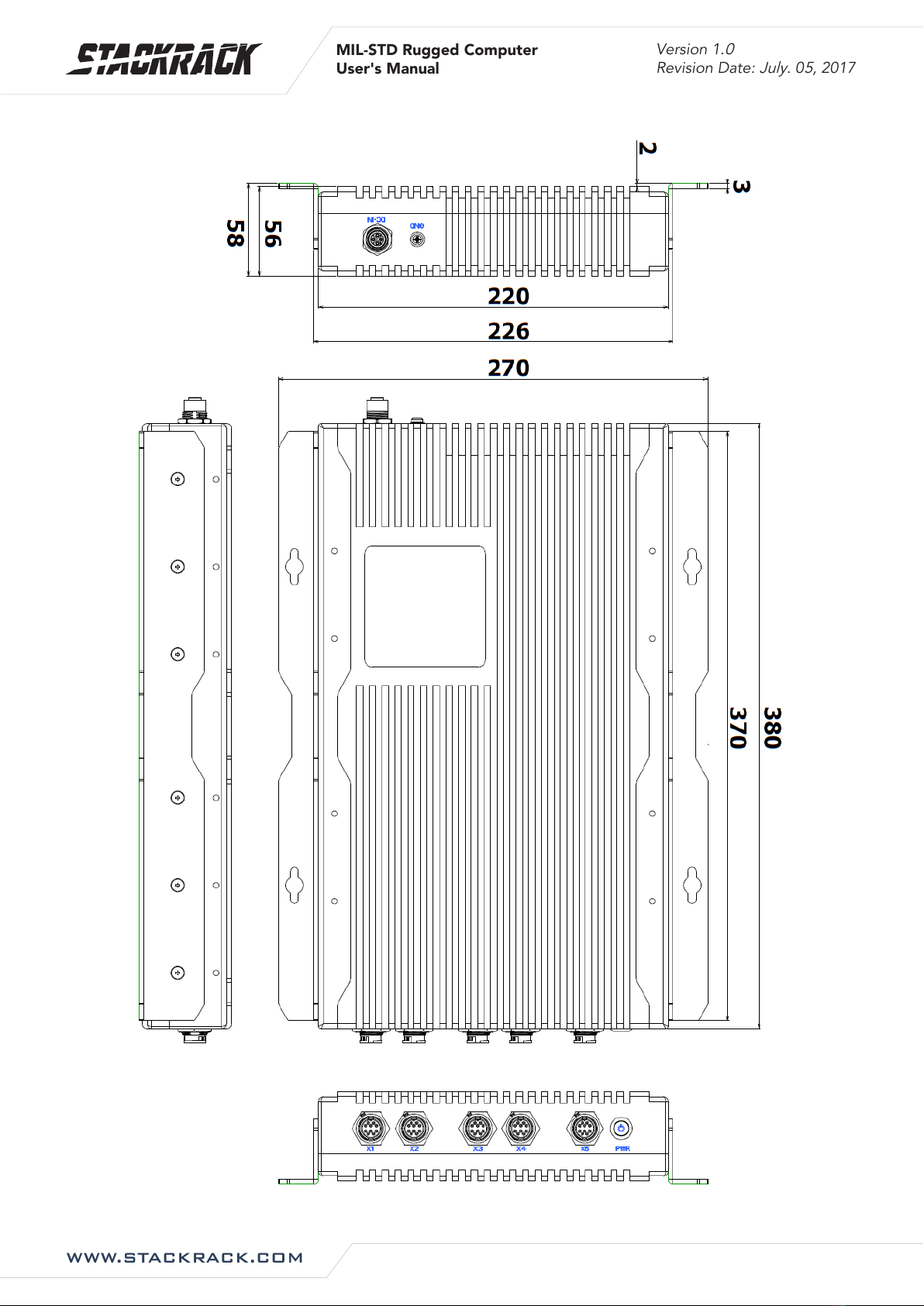
1.2 MECHANICAL DIMENSIONS.................................................................................................................................... 7
CHAPTER 2: JUMPERS AND CONNECTORS........................................................................................................... 8
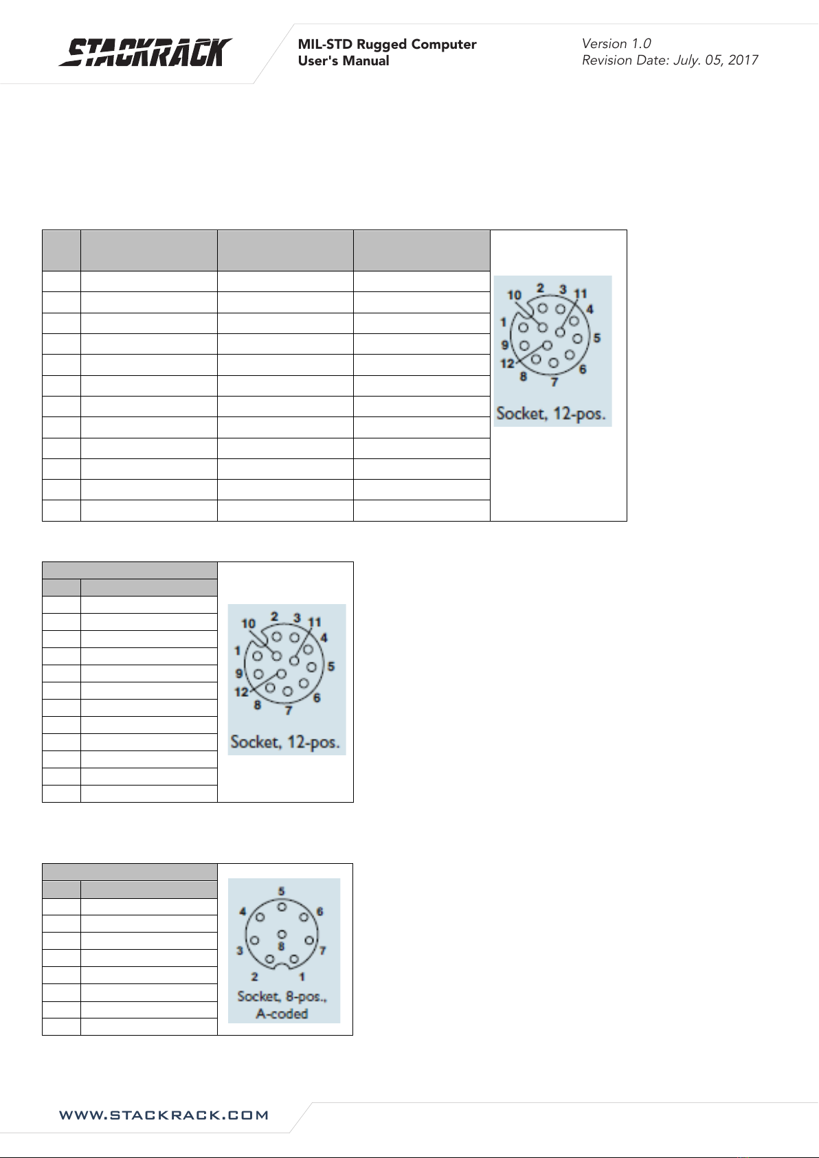
2.1 CONNECTOR PIN DEFINITIONS ............................................................................................................................... 8
X1: COM1: RS232/422/485 with 5V/12V selectable....................................................................................... 8
X2: VGA ............................................................................................................................................................. 8
X3: Intel I210-IT ................................................................................................................................................ 8
X4: Intel I218-LM .............................................................................................................................................. 8
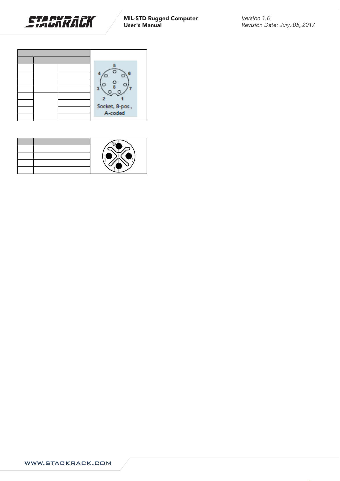
X5: 2 x USB2.0................................................................................................................................................... 9
DC IN: DC Input................................................................................................................................................. 9
CHAPTER 3: AMI BIOS UTILITY........................................................................................................................... 10
3.1 STARTING .........................................................................................................................................................10
3.2 NAVIGATION KEYS .............................................................................................................................................. 10
3.3 MAIN MENU ....................................................................................................................................................11
3.4 ADVANCED MENU ............................................................................................................................................. 12
3.4.1 CPU Configuration.................................................................................................................................13
3.4.2 Trust Computing.................................................................................................................................... 14
3.4.3 ACPI Setting ...........................................................................................................................................14
3.4.4 AMT Setting...........................................................................................................................................15
3.4.5 IT8786 Super IO Configuration.............................................................................................................15
3.4.5.1 Serial Port 1 Configuration ........................................................................................................... 16
3.4.5.2 Serial Port 2 Configuration ........................................................................................................... 16
3.4.5.3 Serial Port 3 Configuration ........................................................................................................... 17
3.4.5.4 Serial Port 4 Configuration ........................................................................................................... 17
3.4.6 Hardware Monitor ................................................................................................................................18
3.4.7 F81216SEC Super IO Configuration......................................................................................................18
3.4.8 SATA Configuration................................................................................................................................ 19
3.4.9 USB Configuration.................................................................................................................................19
3.4.10 Intel I218-LM Ethernet Controller......................................................................................................20
3

WWW.STACKRACK.COM
Version 1.
0
Revision Date:
July
. 0
5
, 2017
MIL-STD Rugged Computer
User's Manual
3.4.10.1 NIC Configuration ....................................................................................................................... 20
3.4.11 Intel I210-IT Ethernet Controller ........................................................................................................ 21
3.4.11.1 NIC Configuration ....................................................................................................................... 21
3.5 CHIPSET MENU .................................................................................................................................................22
3.5.1 System Agent (SA) Configuration .........................................................................................................22
3.5.1.1 Graphics Configuration................................................................................................................. 23
3.5.1.1.1 LCD Control ............................................................................................................................ 23
3.5.1.2 Memory Configuration ................................................................................................................. 24
3.5.2 PCH-IO Configuration............................................................................................................................ 24
3.5.2.1 PCH Azalia Configuration.............................................................................................................. 25
3.5.2.2 BIOS Security Configuration ......................................................................................................... 25
3.5.2.3 Restore AC Power Loss ................................................................................................................. 26
3.5.2.4 Wake on LAN (I218) ...................................................................................................................... 26
3.6 SECURITY MENU................................................................................................................................................27
3.7 BOOT MENU.....................................................................................................................................................28
3.7.1 Boot Option...........................................................................................................................................28
3.8 SAVE & EXIT .....................................................................................................................................................29
4

WWW.STACKRACK.COM
Version 1.
0
Revision Date:
July
. 0
5
, 2017
MIL-STD Rugged Computer
User's Manual
Chapter 1: Product Introduction
1.1 Key Features
System
CPU
Intel® Core™ i7 Broadwell , BGA type Core i7-5650U (2C x 2.2/3.1 GHz),
4M Cache (15W)
Ethernet Chipset
Intel® I210-IT & I218-LM GbE
NOTICE: If you need hot plug function, please disable ULP function of I218-LM.
“ULP Disable.pdf” file could be found in LAN folder of Driver CD.
Memory
2 x DDR3L 1600 XR-DIMM up to 16 GB
Expansion Slot
2 x mPCIe (1 with mSATA supported)
Storage Device
Onboard uSSD SATAIII 64 GB
1 x 2.5” HDD/SSD Slot
1 x mSATA
Front I/O
Power Button
Power Button with LED backlight
X1 (M12 12 pin A-code)
RS232/422/485 COM port
X2 (M12 12 pin A-code)
VGA
X3 (M12 8 pin A-code)
Intel I218-LM GbE LAN
X4 (M12 8 pin A-code)
Intel I210-IT GbE LAN
X5 (M12 8 pin A-code)
2 x USB2.0
Rear I/O
DC-IN (M12 4 pin S-code)
1
Ground Screw
1
Display
GPU
NVIDIA GT730M
Display Interface
VGA
Mechanical & Environment
Power Requirements
9V to 36V DC-in, AT/ATX mode supports with power delay on/off
Power consumption : Under 60 Watt while system fully loading
Dimension
(W xHxD)
220 x 56 x 380 mm
(8.66" x 2.20" x 14.96")
Weight
7.5 kgs
Operating Temp.
-40 to 70°C (ambient with air flow)
Storage Temp.
-40 to 85°C
Relative Humidity
5% to 95%, non-condensing
Serial Interface & Signals
Serial Standards
1x RS-232/422/485 port, mode could be selected in BIOS
RS-232
TxD, RxD, DTR, DSR, RTS, CTS, DCD, GND
RS-422
TxD+, TxD-, RxD+, RxD-, GND
RS-485-4w
TxD+, TxD-, RxD+, RxD-, GND
RS-485-2w
Data+, Data-, GND
Standards and Certifications
MIL-STD-810G Test
Method 507.5, Procedure II (Temperature & Humidity)
5

WWW.STACKRACK.COM
Version 1.
0
Revision Date:
July
. 0
5
, 2017
MIL-STD Rugged Computer
User's Manual
Method 514.6, Procedure I (Category 20 & 24, Vibration)
Method 516.6, Procedure I (Mechanical Shock)
Method 501.5, Procedure I (Storage/High Temperature)
Method 501.5, Procedure II (Operation/High Temperature)
Method 502.5, Procedure I (Storage/Low Temperature)
Method 502.5, Procedure II (Operation/Low Temperature)
Method 503.5, Procedure I (Temperature shock)
EMC
CE and FCC compliance
Green Product
RoHS, WEEE compliance
*Specifications are subject to change without notice*
6

WWW.STACKRACK.COM
Version 1.
0
Revision Date:
July
. 0
5
, 2017
MIL-STD Rugged Computer
User's Manual
1.2 Mechanical Dimensions
7

WWW.STACKRACK.COM
Version 1.
0
Revision Date:
July
. 0
5
, 2017
MIL-STD Rugged Computer
User's Manual
Chapter 2: Jumpers and Connectors
2.1 Connector Pin Definitions
X1: COM1: RS232/422/485 with 5V/12V selectable
RS232/422/485 mode could be changed in BIOS setting.
Pin
RS-232
(Default)
RS-422
RS-485
1
DCD
TX-
D-
2
RXD
TX+
D+
3
TXD
RX+
4
DTR
RX-
5
GND
6
DSR
7
RTS
8
CTS
9
RI (Default)
10
11
12
X2: VGA
LAN
PIN
DEFINITION
1
RED
2
R Ground
3
GREEN
4
G Ground
5
BLUE
6
B Ground
7
H-Sync
8
Ground
9
V-Sync
10
Ground
11
DDC DATA
12
DDC LOCK
X3: Intel I218-LM
X4: Intel I210-IT
LAN
PIN
DEFINITION
1
D1+
2
D1-
3
D2+
4
D2-
5
D3+
6
D3-
7
D4+
8
D4-
8

WWW.STACKRACK.COM
Version 1.
0
Revision Date:
July
. 0
5
, 2017
MIL-STD Rugged Computer
User's Manual
X5: 2 x USB2.0
USB2.0
PIN
DEFINITION
1
USB1
VCC
2
D-
3
D+
4
Gound
5
USB2
VCC
6
D-
7
D+
8
Gound
DC IN: DC Input
PIN
DEFINITION
1
+
2
NA
3
-
4
Ground
9

WWW.STACKRACK.COM
Version 1.
0
Revision Date:
July
. 0
5
, 2017
MIL-STD Rugged Computer
User's Manual
Chapter 3: AMI BIOS UTILITY
This chapter provides users with detailed descriptions on how to set up a basic system configuration
through the AMI BIOS setup utility.
3.1 Starting
To enter the setup screens, perform the following steps:
Turn on the computer and press the <Del> key immediately.
After the <Del> key is pressed, the main BIOS setup menu displays. Other setup screens can be
accessed from the main BIOS setup menu, such as the Chipset and Power menus.
3.2 Navigation Keys
The BIOS setup/utility uses a key-based navigation system called hot keys. Most of the BIOS setup utility
hot keys can be used at any time during the setup navigation process.
Some of the hot keys are <F1>, <F10>, <Enter>, <ESC>, and <Arrow> keys.
Some of the navigation keys may differ from one screen to another.
Left/Right
The Left and Right <Arrow> keys moves the cursor to select a menu.
Up/Down
The Up and Down <Arrow> keys moves the cursor to select a setup
screen or sub-screen.
+− Plus/Minus
The Plus and Minus <Arrow> keys changes the field value of a
particular setup setting.
Tab
The <Tab> key selects the setup fields.
F3
The <F3> key load optimized defaults.
F4
The <F4> key saves any changes made and exits the BIOS setup
utility.
Esc
The <Esc> key discards any changes made and exits the BIOS setup
utility.
Enter
The <Enter> key displays a sub-screen or changes a selected or
highlighted option in each menu.
10

WWW.STACKRACK.COM
Version 1.
0
Revision Date:
July
. 0
5
, 2017
MIL-STD Rugged Computer
User's Manual
3.3 Main Menu
The Main menu is the first screen that you will see when you enter the BIOS Setup Utility.
11

WWW.STACKRACK.COM
Version 1.
0
Revision Date:
July
. 0
5
, 2017
MIL-STD Rugged Computer
User's Manual
3.4 Advanced Menu
The Advanced Menu allows you to configure your system for basic operation. Some entries are defaults
required by the system board, while others, if enabled, will improve the performance of your system or let
you set some features according to your preference. Setting incorrect field values may cause the system to
malfunction.
12

WWW.STACKRACK.COM
Version 1.
0
Revision Date:
July
. 0
5
, 2017
MIL-STD Rugged Computer
User's Manual
3.4.1 CPU Configuration
This page allows you to configure CPU menu.
13

WWW.STACKRACK.COM
Version 1.
0
Revision Date:
July
. 0
5
, 2017
MIL-STD Rugged Computer
User's Manual
3.4.2 Trust Computing
3.4.3 ACPI Setting
14

WWW.STACKRACK.COM
Version 1.
0
Revision Date:
July
. 0
5
, 2017
MIL-STD Rugged Computer
User's Manual
3.4.4 AMT Setting
3.4.5 IT8786 Super IO Configuration
15

WWW.STACKRACK.COM
Version 1.
0
Revision Date:
July
. 0
5
, 2017
MIL-STD Rugged Computer
User's Manual
3.4.5.1 Serial Port 1 Configuration
3.4.5.2 Serial Port 2 Configuration
16

WWW.STACKRACK.COM
Version 1.
0
Revision Date:
July
. 0
5
, 2017
MIL-STD Rugged Computer
User's Manual
3.4.5.3 Serial Port 3 Configuration
3.4.5.4 Serial Port 4 Configuration
17

WWW.STACKRACK.COM
Version 1.
0
Revision Date:
July
. 0
5
, 2017
MIL-STD Rugged Computer
User's Manual
3.4.6 Hardware Monitor
3.4.7 F81216SEC Super IO Configuration
* To use this function should stacked with SK303.
18

WWW.STACKRACK.COM
Version 1.
0
Revision Date:
July
. 0
5
, 2017
MIL-STD Rugged Computer
User's Manual
3.4.8 SATA Configuration
3.4.9 USB Configuration
19
Table of contents