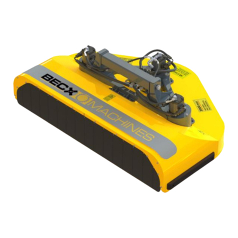
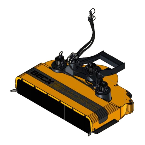
Becx Machines HS75HR User manual

Hedge trimmer
Type: HS130HR
Version: 04
July 2019
Hedge trimmer
HS75HR
User manual

Hedge trimmer
Type: HS75HR
Version: 01
July 2019
Page 2 of 35
Manufacturer Becx Machines B.V.
De Sonman 35
5066 GJ Moergestel
Tel: +31 (0) 13 2070760
www.becxmachines.com
© Copyright 2019
Nothing in this publication may be replicated and/or published in print, photocopy, microfilm, sound
recording, electronically or otherwise without the prior explicit written permission from Becx
Machines B.V.
Becx Machines B.V. retains the right to change parts of the system and the contents of this manual at
any time without prior notification giving or immediate notice to the customer.
Becx Machines B.V. takes the greatest care to guarantee an accurate, and where necessary, complete
description of all parts. Nevertheless, it cannot be held liable for damage due to inaccuracies and/or
deficiencies in this manual.

Hedge trimmer
Type: HS75HR
Version: 01
July 2019
Page 3 of 35
Foreword
The Becx hedge trimmer is specially developed to trim in a safe and efficient manner.
Each blade head is provided with a double row of blades such that extra fine trimming is possible.
Combined with the five-sided guards, the risk of sprigs flying away is prevented. The hedge trimmer
is constructed so that it continues to work and has a long lifespan even under the most demanding
circumstances. Each blade head has its own hydraulic motor. The axles and the bearings are heavy
duty.
Please read this manual carefully before you use the hedge trimmer.
Always observe the safety requirements as set out in Section 2.
A copy of this manual must be kept with the hedge trimmer and be
available to the user. All important maintenance work and relevant
notes must be recorded by the maintenance company.
It is the user’s responsibility to select a suitable tool holder for the
hedge trimmer and ensure that it is correctly attached and
connected to the arm.

Hedge trimmer
Type: HS75HR
Version: 01
July 2019
Page 4 of 35
Table of contents
FOREWORD.................................................................................................................................. 3
TABLE OF CONTENTS .................................................................................................................... 4
DECLARATION OF CONFORMITY (IIA) (COPY)................................................................................. 5
OVERVIEW OF SYMBOLS............................................................................................................... 6
1) TECHNICAL DETAILS.................................................................................................................. 7
2) SAFETY..................................................................................................................................... 8
2.1 GENERAL .............................................................................................................................. 8
2.2 DURING USE.......................................................................................................................... 8
2.3 OPERATING PERSONNEL: .......................................................................................................... 9
2.4 WARNING SYMBOLS ON THE MACHINE....................................................................................... 10
3) DESCRIPTION OF COMPONENTS.............................................................................................. 11
3.1 MECHANICAL COMPONENTS.................................................................................................... 12
3.2HYDRAULIC COMPONENTS ...................................................................................................... 14
3.3 HYDRAULIC DIAGRAM ............................................................................................................ 15
4) OPERATION............................................................................................................................ 16
4.1 ASSEMBLY AND ADJUSTMENT OF THE HEDGE TRIMMER................................................................... 16
4.2 CARRYING OUT THE TRIMMING WORK........................................................................................ 18
4.3 STORAGE ............................................................................................................................. 21
5) MAINTENANCE................................................................................................................. 22
5.1 REPLACING AND/OR SHARPENING THE BLADES............................................................................. 24
5.2 TIGHTENING TORQUES ........................................................................................................... 29
6) MALFUNCTION ANALYSIS ................................................................................................. 30
7) DISPOSAL ......................................................................................................................... 31
8) LOGBOOK......................................................................................................................... 32

Hedge trimmer
Type: HS75HR
Version: 01
July 2019
Page 5 of 35
Declaration of conformity (IIa) (copy)
We:
Becx Machines B.V.
De Sonman 35
5066 GJ Moergestel
declare entirely under our own responsibility that the product:
Description :Becx Hedge trimmer
Type : HS75HR
Serial number :…….....................
with respect to this declaration, conforms to the provisions of the Directives:
Machinery directive 2006/42/EC
In accordance with the following standards:
NEN-EN-12100 Safety of machinery. Basic concepts, general principles for design.
NEN-EN ISO 4413 Hydraulic fluid power - General rules and safety requirements for
systems and their components
NEN-ISO 4254-1 Agricultural machinery - Safety - Part 1: General requirements
Director, Erwin Hommen
The Netherlands, Moergestel,
Date: .........................

Hedge trimmer
Type: HS75HR
Version: 01
July 2019
Page 6 of 35
Overview of symbols
All actions and situations risking the safety of the operator and/or technician and where actions must be
carried out carefully will refer to the following symbols in this user manual:
Take note!
Explanation.

Hedge trimmer
Type: HS75HR
Version: 01
July 2019
Page 7 of 35
1) Technical details
Description
Value
Unit
General
Sound pressure
See tool holder
dB(A)
Vibration level during normal use
N/A
Cutting capacity
20
mm
Required output
10
Kw
Physical data
Width
847
mm
Length
1200
mm
Height
390
m
Unladen weight (see Figure 8:4)
90
kg
Attachment details
Standard fixing sleeve
80*80
mm
Available installation width
mm
Fixing sleeve with modification piece (optional)
70*70
mm
The force on the attachment point (see Figure 8:1)
N
Suspension torque (see Figure 8:2)
Nm
Connection details
Maximum operating pressure
180
bar
Maximum revolutions
3000
-/min
Maximum oil flow (at 3,000 RPMs)
28
L/min
Pressure line connection: flat-face quick-release coupling
1/2”
Return line connection: flat-face quick-release coupling
1/2”
Leak line connection: flat-face quick-release coupling
3/8”
Maximum pressure on the leak line
no pressure
bar
Requirements for filtering hydraulic oil
10
micron
Oil for the drive
HV-46 or equivalent
Grease for lubricating blade heads
NLGI 2
Figure 1: dimensions

Hedge trimmer
Type: HS75HR
Version: 01
July 2019
Page 8 of 35
2) Safety
2.1 General
The hedge trimmer may not be modified.
Only blades conforming to the supplier’s specifications may be mounted.
If individuals carry out work near the blades, they risk being cut by the
trimming side.
It is the user’s responsibility to ensure that the correct tool holder and support
arm is used (see Section 0:1) Technical details). To this end, the following
points are important:
The maximum pressure and rotational speed (oil flow) must not be
exceeded. Exceeding these limits may damage the installation and injure
bystanders.
The support arm and tool holder must be sufficiently strong and stable
enough to bear the forces and torques caused by the hedge trimmer in all
circumstances.
2.2 During use
Consult the tool holder manual for the resulting sound load. As this is
significantly higher than the sound produced by the hedge trimmer, the sound
load from the tool holder is leading.
The installation may only be used for the work activities it is designed for.
The trimmer is not suited for work activities at ground level. There is a high
risk that the blades come into contact with the ground and/or obstacles due
to the construction of the hedge trimmer.
If people or animals approach or enter the safety zone, the hedge trimmer
and the work activities must be stopped immediately (see 4.2). This also
applies to situations where the hedge trimmer will be switched on for testing
after maintenance, etc.
If passers by constantly interrupt the work activities too much, consideration
should be given to fencing off the work area.
If the hedge trimmer begins to make a different sound and/or starts to
vibrate, the work and the hedge trimmer must be immediately stopped (see
4.2). The work must not restart until the cause is found and resolved.
If not trimming, the hedge trimmer must always be turned off. Thus, this also
includes the times when driving to the work area. At these times, there is
higher risk of coming into contact with bystanders during the trimming. In
these situations, the hedge does not act as protection and the driving route is
more difficult to estimate for bystanders or passers by. If there is no hedge,
parts can fly away unhindered over a large distance.
Inspection and maintenance work must be carried out.
During inspection and maintenance, the installation must not be used for

Hedge trimmer
Type: HS75HR
Version: 01
July 2019
Page 9 of 35
other purposes.
During inspection, maintenance, or cleaning, the hydraulic feed to the hedge
trimmer must be disconnected to prevent it being accidentally switched on.
The local work and safety regulations must be observed.
If the installation is to be used in the dark, sufficient lighting must be used
(approx. 50 lux on the place of operation).
Trimming work must be stopped immediately when people or animals
approach or enter the safety zone. (see 4.2)
To prevent damage to the installation, the device must be gradually switched
off using the lowest RPMs. Depending on the tool holder used, this is idling
speed or the minimal flow.
2.3 Operating personnel:
Operating personnel must be older than 18 years of age.
Only individuals authorized by the owner may work on or with the installation.
Operators may only perform work activities that they are trained for. This
applies to both the maintenance work and normal usage.
The operating personnel must be acquainted with all situations that can
occur.
If the operating personnel discover faults or risks or do not agree with the
safety measures, this must be reported to the owner or person in charge.

Hedge trimmer
Type: HS75HR
Version: 01
July 2019
Page 10 of 35
2.4 Warning symbols on the machine
1.
Cutting danger
2.
Read the manual before you use the machine!
3.
See safety zone (4.2)

Hedge trimmer
Type: HS75HR
Version: 01
July 2019
Page 11 of 35
3) Description of components
Figure 2: Overview photo
Figure
element
explanation
1
Support arm
The support arm is not part of the delivery. It is the user’s
responsibility to ensure that a suitable support arm is used
for the hedge trimmer.
2
Hedge trimmer
The hedge trimmer can be used horizontally, vertically, and in
all intermediate angles.
3
Tool holder
The tool holder is not part of the delivery. It is the user’s
responsibility to ensure that a suitable tool holder is used for
the hedge trimmer.
1
2
3

Hedge trimmer
Type: HS75HR
Version: 01
July 2019
Page 12 of 35
3.1 Mechanical components
Figure 3: Overview of mechanical components
Figure
element
explanation
1
Fixing sleeve
The hedge trimmer is attached to the arm of the tool holder
using the fixing sleeve.
2
Angle inclination
Once the hedge trimmer is fastened to the arm, the correct
angle can be set. (see paragraph 4.1)
3
Hydraulic motor
(3*)
Each blade head is driven by its own hydraulic motor.
4
Inlet side
During trimming, the twigs to be cut enter the inlet side
through the protective flaps of the PUR SH 90 A near the
blade heads.
5
Blade head (3*)
Each blade head has four blades. The two blades on the
lower layer cut the hedge twigs. The two blades on the upper
layer shred the sprigs into small pieces.
6
Protective cover
The protective cover is made of high-quality steel and
prevents cut material from flying away.
4
3
1
2
6
5

Hedge trimmer
Type: HS75HR
Version: 01
July 2019
Page 13 of 35
Figure 4: Dimension sketch of blade path
Figure 5: Dimension sketch of cover-seal front side (Material: PUR SH 90 A)

Hedge trimmer
Type: HS75HR
Version: 01
July 2019
Page 14 of 35
Figure 6: Dimension sketch of blades in relation to the cover
3.2 Hydraulic components
Figure 7: Overview of hydraulic components
Figure 7
element
explanation
1
Hydraulic motor
(3*)
Each hydraulic motor has a connection for a supply line, a
return line, and a leak line. The three motors are linked in
series such that the hedge trimmer can be connected with
one supply line, outlet line, and leak line.
The rotation direction is safeguarded with a built-in non-
return valve.
2
Leak line quick-
release coupling
A separate leak line on the tool holder returns the leaked oil
from the motors to the hydraulic generator.
3
Supply line quick-
release coupling
The hydraulic oil is supplied by the hydraulic generator.
4
Outlet line quick-
release coupling
The hydraulic oil is returned to the hydraulic generator.
4
3
1
2

Hedge trimmer
Type: HS75HR
Version: 01
July 2019
Page 15 of 35
3.3 Hydraulic diagram

Hedge trimmer
Type: HS75HR
Version: 01
July 2019
Page 16 of 35
4) Operation
4.1 Assembly and adjustment of the hedge trimmer
Figure 8: adjusting the hedge trimmer horizontally
No.
What to do
Action
Result
1
Select the correct tool
holder and support
arm.
ensure that the tool holder and support arm
are sufficiently strong and stable enough for
the hedge trimmer (see Figure 8 and Section
0:1) Technical details for the unladen weight,
the load in the nesting place (Figure 8.1), and
the resulting torque in the nesting place
(Figure 8Figure 8:2).
Ensure that the maximum pressure and
rotational speed (oil flow) cannot be
exceeded.
Ensure the correct quick-release couplings
are attached for the supply, return, and leak
lines.
Ensure that the correct coupling is attached.
Not respecting the
specified limits
may damage the
installation and
injure bystanders.
1
2
3
4
5

Hedge trimmer
Type: HS75HR
Version: 01
July 2019
Page 17 of 35
2
Adjust the hedge
trimmer horizontally
Depending on the curvature of the support
arm, the underside of the hedge trimmer
(see Figure 8Figure 8:5) will not hang
completely horizontally.
Adjust the angle setting (see Figure 8Figure
8:3) so that the cover hangs horizontally
when it is tilted up.
The optimal
trimming result is
achieved when the
underside of the
protective cover is
parallel to the
cutting surface.
3
Connect the hoses
Connect the quick-release couplings for the
supply, return, and leak lines (see Figure 7).
4
Adjust the oil supply.
Adjust the generator for the tool holder so
that the maximum pressure and rotational
speed cannot be exceeded.
This depends on the type of tool holder
used. See the tool holder manual.

Hedge trimmer
Type: HS75HR
Version: 01
July 2019
Page 18 of 35
4.2 Carrying out the trimming work
Figure 9: overview of safety zone up to one-meter cutting height in horizontal position
Cutting height
safety radius
Safety distance at the front
0-1 m
5 m
10 m
1.1-1.2 m
6 m
11 m
1.2-1.3 m
7 m
12 m
1.3-1.4 m
8 m
13 m
1.4-1.5 m
9 m
14 m
> 1.5 m
10 m
15 m
Table 1: Cutting height –safety distance in horizontal position

Hedge trimmer
Type: HS75HR
Version: 01
July 2019
Page 19 of 35
Figure 10: overview of safety zone up to one-meter cutting height in vertical position
Cutting height
safety radius
Safety distance at the front
0-1 m
10 m
10 m
1.1-1.2 m
11 m
11 m
1.2-1.3 m
12 m
12 m
1.3-1.4 m
13 m
13 m
1.4-1.5 m
14 m
14 m
> 1.5 m
15 m
15 m
Table 2: Table cutting height –safety distance in vertical position

Hedge trimmer
Type: HS75HR
Version: 01
July 2019
Page 20 of 35
No.
What to do
Action
Result
1
Check the
installation
check the following points:
check the blades:
The blades must not be worn away too much and
must be in balance (see 0).
Check the blades for damage and cracks before
starting work, after four hours of trimming, or
immediately after the blades come into contact with
materials other than that intended.
At a minimum, each day, visually check that the locking
plate and locking nuts of the blade head are present.
Check that the rotation direction of the blades matches
the arrow on the housing.
Check the rotational speed of the blades.
Check that the blades work without vibrating.
If one of the above checks discovers a deficiency, it must
first be rectified before the hedge trimmer can be used.
Continuing to
work with loose
locking nuts,
cracked blades, or
with an
installation that
runs poorly or too
quickly may cause
damage to the
installation
and/or injure the
operator or
bystanders.
2
Check the work
area.
Check the hedge to be trimmed and the surrounding area
on the following points:
Are obstacles present that could be damaged by the
hedge trimmer or that could cause damage to the hedge
trimmer?
Are there any loose elements, such as litter, loose iron
wire, and so on?
Ensure that there are no people or animals within the
safety zone.
If lots of passers by would cause the work to be stopped
often, the work area must be fenced off.
The work area must be fenced off when the hedge is tall
and so dense that it blocks the overview of the other
side.
At all times, measures must be in place to prevent
anyone being present on the other side of a non-
transparent hedge.
Take this into
account when
trimming.
Remove loose
items to prevent
damage to the
hedge trimmer.
3
Drive to the
work area
Always switch off the hedge trimmer when it is not being
used to trim.
The chance that a bystander enters the danger zone
unnoticed is greater during the trimming.
If there is no hedge, parts can fly away unhindered over a
large distance.
Table of contents
Other Becx Machines Trimmer manuals
Popular Trimmer manuals by other brands

Sinbo
Sinbo SHC 4375 instruction manual

Makita
Makita DUR141 instruction manual

KRESS
KRESS Commercial KC100 Series instruction manual
GARDEO PRO
GARDEO PRO GTHT26RH-BAG Original instructions
Andis
Andis Pivot Pro Trimmer PMT-1 Specification sheet

FRANCK PROVOST
FRANCK PROVOST THE BARB' XPERT FPH-004 instruction manual
