manuals.online logo
Brands
  1. Home
  2. •
  3. Brands
  4. •
  5. Beechcraft
  6. •
  7. Tools
  8. •
  9. Beechcraft Baron 58TC 1982 Quick start guide

Beechcraft Baron 58TC 1982 Quick start guide

ATP
INDEX
COPYRIGHT 2002
COPYRIGHT IS NOT CLAIMED AS TO ANY PART OF AN ORIGINAL WORK
PREPARED BY A UNITED STATES GOVERNMENT OFFICER OR EMPLOYEE AS
PART OF THAT PERSONS OFFICIAL DUTIES OR BY ANY OTHER THIRD PARTY
OFFICER OR EMPLOYEE AS PART OF THAT PERSONS DUTIES.
"ATP" is a registered trademark of Aircraft Technical Publishers. All original
authorship of ATP is protected under U.S. and foreign copyrights and is subject
to written license agreements between ATP and its Subscribers.
ALL RIGHTS RESERVED. NO PART OF THIS PUBLICATION MAY BE
REPRODUCED, STORED IN A RETRIEVAL SYSTEM, OR TRANSMITTED IN ANY
FORM BY ANY MEANS, ELECTRONIC, MECHANICAL, PHOTOCOPYING,
RECORDING OR OTHERWISE, WITHOUT PRIOR WRITTEN PERMISSION OF THE
PUBLISHER.
AIRCRAFT
TECHNICAL
PUBLISHERS
CUSTOMER
SERVICf
101
SOUTH
HILL
DRIVE
6AM-5PM
PST
M-f
BRISBANE,
CA
94005
(800)227-451(
ATP
GRID
INDEX
TO
MANUFACTURER’S
PUBLICATION:
BEECH
AIRCRAFT
CORP.
58TC/TCA
S/N
57
ON
WIRING
MANUAL
SECTION
TOPIC
GENERAL
INFORMATION
TITLE
PAGE
MANUFACTURER’S
INTRODUCTION
RECORD
OF
REVISIONS
RECORD
OF
TEMPORARY
REVISIONS
ALPHABETICAL
INDEX
ALPHA-NUMERIC
INDEX
AIRFRAME
SYSTEMS
21.00.00
AIR
CONDITIONING
23.00.00
LIST
OF
EFFECTIVE
PAGES
21.40.00
HEATING
21.40.01
HEATING
(fi(-57
MRU
fit-82
21.40.02
HEATING
(TK-83
THRU
TI(-90)
25.40.03
HEATING
(TK-91
THRU
TK-137)
21.40.04
HEATING
(TK-138
AFTER)
21.50.00
COOLING
21.51.01
VENT
AIR
BLOWER
(OPTIONAL)
21.52.01
BLOWERS-AIR
CONDITIONING
(OPTIONAL)
25.53.01
AIR
CONDITIONING
(OPTIONAL)
23.00.00
COMMUNICATIONS
23.00.00
LIST
OF
EFFECTIVE
PAGES
23.10.00
SPEECH
COMMUNICATION
23.10.01
MIC
SWITCH
CONTROL
WHEEL
(OPTIONAL)
24.00.00
ELECTRICAL
POWER
24.00.00
LIST
OF
EFFECTIVE
PAGES
02/24/98
Copyright
(c)1998
Aircraft
Technical
Publishers
PAGE:
1
(RCR2102)
(BC
0455
WD)
SECTION
TOPIC
24.30.00
DC
GENERATION
24.30.01
Lf
ALTERNATOR
AND
REGULATOR
(TK-57
THRU
TK-73)
24.30.02
Lf
ALTERNATOR
AND
REGULATOR
(TK-74
THRU
TK-133)
24.30.03
LH
ALTERNATOR
AND
REGUALTOR
(TK-134
AFTER)
24.31.01
RH
ALTERNATOR
AND
REGUALTOR
(TK-57
MHRU
TK-73)
24.31.02
RH
ALTERNATOR
AND
REGULATOR
(TK-74
MRU
Tf(-133)
24.31.03
RH
ALTERNATOR
AND
REGULATOR
(TK-134
AFTER)
24.32.01
BATTERY
(TK-57
THRU
TK-99)
24.32.02
BATTERY
(TK-100
AFTER)
24.40.00
EXTERNAL
POWER
24.40.01
EXTERNAL
POWER
(OP’I"IONAL)
24.50.00
ELECTRICAL
LOAD
DISTRIBUTION
24.50.01
W/O
ALTERNATE
805
(TK-57
THRU
TK-106
TK-109)
24.50.02
W/O.ALTERNATE
BUS
(TK-107,
TK-108,
TK-IIO
MRU
fi(-l45)
24.50.03
W/O
;4LTERNATE
8US
(iK-146
AFTER)
24.51.01
WITH
ALTERNATE
BUS
(TK-57
MRU
TK-106
TK-109)
24.51.02
WITH
ALTERNATE
BUS
(TK-107,
TK-IIO
THRU
TK-145)
24.51.03
WITH
ALTERNATE
BUS
(TK-146
AFTER)
25.00.00
EQUIPMENT~’IR1RNISHINGS
25.00.00
LIST
OF
EFFECTIVE
PAGES
25.10.00
FLIGHT
COMPARTMEM
25.10.01
CIGARETTE
LIGHTER
CTK-57
THRU
TK-LOG
TK-109)
25.10.02
CIGARETTE
LIGHTER
(TK-107,
TK-108,
TK-IIO
AFTER)
25.11.01
QUARTZ
DIGITAL
CHRONOMETER
(TK-57
THRU
TK-99)
25.11.02
QUARTZ
DIGITAL
CHRONOMETER
(TK-100
AFTER)
25.60.00
EMERGENCY
25.60.01
EMERGENCY
LOCATOR
TRANSMITTER
27.00.00
FLIGHT
CONTROLS
27.00.00
LIST
OF
EFFECTIVE
PAGES
27.30.00
ELEVATOR
AND
TAB
27.39.01
STALL
WARNING
27.31.02
STALL
WARNING
(~PTIONAL)
27.32.01
ELEVATOR
TRIM
27.50.00
FLAPS
27.50.01
PERMANENT
MAGNET
MOTOR
(TK-57
THRU
TK-66)
27.50.02
PERMANENT
MAGNET
MOTOR
(fK-67
THRU
TK-90)
27.50.03
PERMANENT
MAGNET
MOTOR
(TK-91
AFTER)
27.51.01
POSITION
INDICATOR
28.00.00
FUEL
28.00.00
LIST
OF
EFFECTIVE
PAGES
28.10.00
STORAGE
28.10.01
FUEL
VENT
HEATERS
28.20.00
DISTRIBUTION
28.20.01
FUEL
BOOST
PUMPS
(TK-57
THRU
TK-84)
28.20.02
FUEL
BOOST
PUMPS
(TK-85
THRU
TK-102)
28.20.03
FUEL
BOOST
PUMPS
(TK-T03
AFTER)
28.40.00
INDICATING
02124/98
Copyright:
(c)1998
Aircraft
Technica7
Pub7is~ers
PAGE:
2
(RCR2102)
(BC
0455
b(D)
SECTION
TOPIC
28.40.01
FUEL
QUANTITY
(TK-57
THRU
TK-106
TK-109)
28.40.02
FUEL
QLIANTITY
(TK-107,
TK-108,
TK-IIO
THRU
TK-144)
28.40.03
FUEL
CIUANTIT(
(TK-145
AFTER)
30.00.00
ICE
AND
RAIN
PROTECTION
30.00.00
LIST
Of=
EFFECTIVE
PAGES
30.10.00
AIRFOIL
30.10.01
SURf=ACE
DEICER
30.10.02
SURFACE
DEICER
(OPTIONAL)
30.30.00
PITOT
AND
STATIC
30.30,01
HEAT
30.40.00
WINDOWS,
WINDSHIELDS,
AND
DOORS
30.40.01
ANTI-ICE
(OPTIONAL)
30.41.01
ALCOHOL
QUANTITY
(OPTIONAL)
30.42.01
ELECjRO
THERMAL
ANTI-ICE
(OPTIONAL)
30.60.00
PROPELLERS/ROTORS
30.61.01
3-8W)E
ANTI-ICE
(TK-57
THRU
TK-86)
30.61.02
3-BLADE
ANTI-ICE
(TK-87
THRU
‘fK-138)
30.61.03
3-8W1E
DEICE
(TK-139
AFTER)
(OPTIONAL)
31.00.00
INDICATINGIRECORDING
SYSTEMS
31,00.00
LIST
OF
EFFECTIVE
PAGES
31.30.00
RECORDERS
31.30.01
FLIGHT
HOUR
METER
(OPTIONAL)
31.31.01
ENGINE
HOUR
METER
(OPTIONAL)
31.50.00
CENTRAL
WARNING
SYSTEMS
32.51.01
ANNUNCIATOR
LIGHT
TEST
(TK-57
THRU
TK-84)
31.51.02
ANNUNCIATOR
LIGHT
TEST
(TK-8S
AFTER)
31.52.01
ANNUNCIATOR
LIGHTS
(TK-85
THRU
TK-133)
31.52.02
ANNUNCIATOR
LIGHTS
(TK-134
AFTER)
32.00,00
LANDING
GEAR
32.00.00
LIST
OF
EFFECTIVE
PAGES
32.30.00
EXTENSION
AND
RETRACTION
32.30.01
LANDING
GEAR
MOTOR
AND
RELAY
32.30.01
TK-57
THRU
TK-TO
EXCEPT
TK-68
32.30.02
TK-68,
TK-71
THRU
TK-90
32.30.03
TK-91
AFTER
32.31.01
LANDING
GEAR
POSITION
INDICATOR
32.31.01
TK-57
THRU
TK-70
EXCEPT
fit-68
32.31.02
TK-68,
TK-71
MRU
TK-90
32.31.03
TK-91
AFTER
32.60,00
POSITION
AND
WARNING
32.60.01
THROTTLE
(TK-57
THRU
TK-67)
32.60.02
THROTTLE
(TK-68
AFTER)
33.00.00
LIGHTS
33.00.00
LIST
OF
EFFECTIVE
PAGES
33.10.00
FLIGHT
COMPARTMENT
33.11.01
MAP.
COMPASS.
OAT
CLOCK
LIGHTS
02/24/98
Copyright
(c)1998
Aircraft
Technical
Publishers
PAGE:
3
(RCR2102)
(BC
0455
WD)
SECTION
TOPIC
33.11.01
TK-57
THRU
TK-99
33.11.02
TK-100
AFTER
33.12.01
ENGINE
INSTRUMENT
AND
RADIO
LIGHTS.
33.13.01
ENGINE
INSTRUMENT
AND
RADIO
POST
LIGHTS
33.13.01
TK-57
THRU
TK-113
33.13.02
TK-114
THRU
TK-148
33.13.03
TK-L49
AFTER
33.14.01
ENGINE
INSTRUMENT
AND
RADIO
WU]GE
LIGHTS
33.14.01
TK-57
MRU
TK-113
33.14.02
TK-114
THRU
TK-148
33.14.03
TK-149
AFTER
33.15.01
FLIGHT
INSTRUMENT
LIGHTS
33.16.01
FLIGHT
INSTRUMENT
POST
LIGHT
33.16.01
TK-57
THRU
TK-T13
33.16.02
TK-
rid,
THRU
Tif-148
33.16.03
TK-149
AFTER
33.17.01
FLIGHT
INSTRUMENT
WU]GE
LIGHTS
33.17.01
TK-57
MRU
TK-113
33.17.02
TK-114
THRU
TK-148
33.17.03
TK-149
AFTER
33.18.01
FLOODLIGHTS
33.18.01
TK-57
TK-58
33.18.02
fit-59
AFTER
33.19.01
ELECTROLUMINESCENT
PANEL
LIGHTS
33.19.01
TK-57
THRU
TK-145
33.19.02
TK-
146
AFTER
33.20.00
PASSENGER
COMPARTMENT
33.20.01
CABIN
LIGHTS
33.20.01
TK-57
MRU
TI(-106
TK-109
33.20.02
TK-107,
TK-108.
TK-I10
AFTER
33.30.00
CARGO
AND
SERVICE
COMPARTMENTS
33.30.01
BAGGAGE
COMPARTMENT
LIGHTS
33.40.00
EXTERIOR
33.40.01
THREE
STROBE
LIGHT
33.40.01
TK-57
THRU
TK-70
EXCEPT
TK-68
33.40.02
TK-~8.
TK-71
AFTER
33.43.01
TAXI
LIGHT
33.44.01
ROTATING
BEACON
33.45.01
NAVIGATION
LIGHT
33.46.01
LANDING
LIGHTS
33.47.01
ICE
LIGHT
(OPTIONAL)
34.00.00
NAVIGATION
34.00.00
LIST
OF
EFFECTIVE
PAGES
34.20.00
ATTITUDE
AND
DIRECTION
34.20.01
TURN
AND
SLIP
INDICATOR
34.21.01
GYRO
INSTRUMENTS
(OPTIONAL)
STRUCTURE
52.00.00
DOORS
02/24/98
Copyright
(c)1998
Aircraft
Technical
Publishers
PAGE:
4
(RCR2102)
(BC
0455
blD)
SECTION
TOPIC
52.00.00
LIST
OF
EFFECTIVE
PAGES
52.70.00
DOOR
WARNING
52.70.01
CABIN
AND
DOOR
COURTESY
LIGHTS
(TK-57
THRU
fl<-84)
52.70.02
CABIN
AND
DOOR
COURTESY
LIGHTS
(TK-85
THRU
TK-145)
52.70.03
CABIN
AND
DOOR
COURTESY
LIGHTS
(TK-146
AFTER)
PROPELLER/ROTOR
61.00.00
PROPELLERS/PROPUtSORS
61.00,00
LIST
OF
EFFECTIVE
PAGES
61.20.00
CONTROLLING
61.20.01
PROPELLER
SYNCHRONIZER
(TK-57
THRU
TK-60)
(OPTIONAL)
61.20.02
PROPELLER
SYNCHRONIZER
(TK-61
1IIRU
TK-133)
(OPTIONAL)
61.20.03
PROPELLER
SYNCHROPHASER
61.21.01
PROPELLER
GOVERNOR
(TK-57
TIIRU
TK-84)
61.21.02
PROPELLER
GOVERNOR
(n<-85
AFTER)
POWER
PLANT
71.00.00
POWER
PLANT
71.00.00
LIST
OF
Ef=FECTIVE
PAGES
71..10.00
COWLING
71.10.01
FLAPS
73.00.00
ENGINE
FUEL
AND
CONTROL
73.00.00
LIST
OF
EFFECTIVE
PAGES
73.30.00
INDICATING
73.30.01
FUEL
FLOW
SYSTE3
(TK-57
TK-58)
73.30.02
FUEL
FLOW
SYSTEM
(TK-59
AFTER)
74.00.00
IGNITION
74.00.00
LIST
OF
Ef=FECTTVE
PAGES
74.30.00
SWITCHING
74.30.01
IGNITION
77.00.00
ENGINE
INDICATING
77.00.00
LIST
OF
EFFECTIVE
PAGES
77.10.00
POWER
77.10.01
TACHOMETER
77.20.00
TEMPERATURE
77.20.01
RIGHT
CYLINDER
HEAD
AND
OIL
77.21.01
LEFT
CYLINDER
HEAD
AND
OIL
78.00.00
EXHAUST
78.00.00
LIST
OF
EFFECTIVE
PAGES
78.40.00
SUPPLEMENTARY
AIR
78.40.01
EGT
AND
ENGINE
INDICATING
91.00.00
CHARTS
02/24/98
Copyright
(c)1998
Aircraft
rechnica7
Pub‘iishers
PAGE:
5
(RCR2102)
(BC
0455
WD)
SECTION
TOPIC
91.00.00
LIST
OF
EFFECTIVE
PAGES
91.10.01
CONNECTOR
NOSE
ACCESS
91.11.01
CONNECTOR
LH
WING
ACCESS
J50,P50
9’1.11.01
TK-57
MRU
TK-70
EXCEPT
TK-68
91.11.02
TK-68,
TK-71
AFTER
91.12.01
CONNECTOR
U-f
WING
ACCESS
J56,P56
92.12.01
TK-57
THRU
TK-70
EXCEPT
TK-68
91.12.02
TK-68,
TK-71
AFfER
91.13.01
CONNECTOR
13f
ENGINE
ACCESS
351.P51
91.13.01
TK-57
TlfRU
iK-67
91.13.02
n<-ss
A~TER
91.14.01
CONNECTOR
llf
ENGINE
ACCESS
J57,P57
91.15.01
CONNECTOR
RH
WING
ACCESS
552.P52
91.15.02
CONNECTOR
RH
ENGINE
ACCESS
JIP52
91.16.01
CONNECTOR
RH
ENGINE
ACCESS
553,P53
91.16.01
TK-57
TK-58
91.16.02
TK-59
THRU
TK-70
EXCEPT
TK-68
91.16.03
TK-68,
TH-71
AFTER
91.17.02
CONNECTOR
RCI
ENGINE
ACCESS
J58,P58
´•kkk
END
OF
INDEX
jl~-k
02/24/98
Copyright
(c)1998
Aircraft
Technical
Pub7ishers
PAGE:
6
(RCR2102)
(BC
0455
WD)
NI
FG
I
INTRO
TURBOCHARG~ED
~8TC
58TCA
SERIALS
TK-52
AND
AFTER
WIRING
DIAGRAM
MANUAL
COPYRIGHT
O
BEECH
1982
PIN
1016-590000-138
Reissued:
Ney
28,
1982
~T’-
PUBLI9IEO
BY
COMMERCIAL
PROIIUCT
SUPPOKf
BEECR
ATRCRAFf
CORPOI~IION
WICHFTA
KANSAS
U.SA.
M´•nb´•rdOlM*
r~r)
G´•n´•ml*rian
A
Raytbeon
Company
71
M~nuloaumrAadanon
RECORD
OF
RFVISIONS
MFG
NO
DESCRIPT(ON
1SSUEDATE
ATPRNDA’
INSERTED
SY
B
Rei~ue
5~2slsz
319/98
ATPIBP
LIST
OF
EFFECTIVE
REV1SIONSI
Always
destroy
superseded
pages
when
you
insert
revised
pages
Tftle
Page.
,..,....,.......~ay
28,
1982
Logo
Page,...............,......,,........,....,,,,.,,,,,.
"a"
Page,
,~fay
28,
1982
LOG
OF
RF1/ISIONS
fart
Number
Dale
Chapters
Affected
106-590000-13
(orisinar)
~iarch
6,
1978
106-590000-13B
(Reissue)
~iay
28,
1982
NOTE.
A
list
of
the
effective
pages
wilt
be
found
in
the
front
of
each
chapter.
I
B
Baste
publlcattons
are
asstgned
a
part
number
whtch
appears
on
the
title
page
Hnth
the
date
of
the
issue.
Subsequent
rev,slons
are
identllied
by
the
addition
of
a
revrston
code
after
the
pan
number
At
after
a
part
number
denotes
the
bra
rewslon
to
the
base
publication.
A2
the
second.
etc
Occasionally.
It
Is
necessary
to
completely
reissue
and
repnnt
a
publtcalton
for
the
purpose
of
obsoletmg
a
prev~ous
Issue
and
outstanding
re~sions
thereto
As
these
replacement
reissues
are
made.
the
code
wilt
also
change
to
the
next
successive
letter
of
the
alphabet
at
each
issue.
for
example.
a
for
the
first
reissue.
C
for
the
second
retssue.
etc.
When
oidenng
a
handbook.
gtve
the
basrc
number.
andthe
re~ssue
code
when
applicable.
ti
a
complete
up-to-date
pubilcatgn
is
des,red
Should
only
revision
pages
be
required.
g~ve
the
basic
number
and
revision
code
for
the
part~cular
set
of
revslon
pages
~ou
deare
RECORD
OF
~EMPORARY
RFVISIONS
ATP
RE/
INSERT
DATE
REV
REMOVE
RN
NO
DESCRIPTION
ISSUE
DATE
DATE
BY
REMOVED
1NCOR
BY
BEECHCRAFT
BAROH
58TC
WIPING
DIAGRALI
NM1UAL
Introduction
UST
OF
PAGE
EFTrCTn/rrY
CHAPTER
SECTION
SUBJECT
PAGE
DATE
~ntroduction-Effectivity
1
May
28,
1982
Introduction
1
thru
20
May
28.
1982
"EPID"
Introductlon-EHectlvity
Pogo
1
May
28,
1982
BEEC~CRAFT
BARON
581%
WIRING
MAGRAII
MANUAL
INTRODUCTION
NO‘FE
ASSIGNMENT
OF
1~A
~ERIAL
Service
Publications
reissues
or
revisions
are
The
content
of
this
publication
is
organized
at
four
levels:
not
automatically
provided
to
the
holders
of
this
Group,
SystemiChapter,
Sub-SystemiSection,
and
manual.
For
information
on
how
to
obtain
reis-
UnitlSubject.
sues
or
revisions
applicable
to
his
manual,
refer
to
he
latest
revision
of
BEECHCRAFT
Group
Identified
by
different
colored
divider
tabs.
Service
Instructions
No.
0250-010.
These
are
primary
divisions
of
the
manual
that
enable
broad
separation
of
content.
Typical
of
this
division
is
the
separation
between
Airframe
Systems
and
the
The
BEECHCRAFT
Baron
58TC
Wiring
Diagram
Manual
is
Aircraft
Power
Plant.
prepared
in
accordance
with
the
GAMA
Spec.
No.
2
(General
Aviation
Manufacturing
Association).
It
also
meets
The
various
groups
are
broken
down
the
intent
of
the
requirements
of
the
ATA
Specification
100
into
maior
systems
such
as
Environmental
Systems,
(Air
Transport
Association
of
America),
with
respect
to
the
Electrical
Power,
tanding
Gear,
etc.The
systems
are
arrangement
and
content
of
the
system/chapters
within
the
ananged
more
or
less
alphabetically
rather
than
by
designated
chapter
numbering
system,
precedence
or
importance.
They
are
assigned
a
number,
which
becomes
the
first
element
of
a
The
BEECHCFIAFT
Baron
58ZC
Wiring
Diagram
Manual
is
standardized
numbering
system.
Thus,
the
element
"28"
supplemented
by
the
following
publications:
(t)
The
of
the
number
28-00-00
refers
to
the
chapter
"Fuel".
BEECHCRAFT
Baron
58PIBaron
58TC
Maintenance
Everything
concerning
the
fuel
system
win
be
covered
in
Manual
P/N
102-590000-5
(2)
The
BEECHCRAFT
this
chapter.
Illustrated
Parts
Catalog
P/N
102-590000-7
13)
The
BEECH
Manufactured
Components
Maintenance
Manual
Sub-SystemlSection
The
major
systems
of
an
PIN
102-590000-21.
airplane
are
broken
down
into
sub-systems.
These
sub-
systems
are
identified
by
the
second
element
of
a
Refer
to
the
BEECHCRAFT
Baron
58P158TC
Win~ng
standard
numbering
system.
The
number
"40"
of
the
Diagram
Manual
PIN
102-590000-23
for
the
wiring
number
28-40-00
is
for
the
indicating
portion
of
the
fuel
diagrams
perfaining
to
the
Baron
58TC
airplane
serials
TK-
system.
I
thru
TK-56.
UnltlSubject
The
individual
units
within
a
sub-system
may
be
identified
by
the
third
element
of
the
standard
NOT1CE
numbering
system,
such
as
28-40-01.
This
number
is
assigned
by
the
manufacturer
and
may,
or
may
not,
be
Seech
Aircraft
Corporation
expressly
reserves
used
and
vnll
vary
in
usage.
the
right
to
supersede,
cancel
andlor
dedare
obsolete
any
part,
part
numbers,
kits
or
publication
that
may
be
referenced
in
this
APPLICATION
manual
without
prior
notice.
Any
publication
conforming
to
the
GAMA
Spec
2
or
ATA
100
formats
will
use
the
same
basic
numbering
system.
CORRESPONDENCE
Thus
whether
the
manual
be
a
BEECHCRAFT
King
Air
100
Series
Maintenance
Manual,
or
a
BEECHCRAFT
if
a
question
should
arise
concerning
the
care
of
your
Baron
58TC
Series
Wiring
Oiagram
Manual,
the
person
airplane,
it
is
important
to
include
the
airplane
serial
wishing
information
conceming
he
indicating
portion
of
the
number
in
any
conespondence.
The
serial
number
appears
fuel
system
would
refer
to
the
SystermChapter
Tab
"28,
on
the
model
designation
placard
inboard
of
he
right
hand
Fuel."
The
table
of
contents
in
the
front
of
this
chapter
will
flap
on
the
fuselage.
provide
a
Ist
of
sub-systems
covered
in
the
chapter.
INTRODUCflON
Page
May
28,
82
BEECIfCRAFT
BARON
58TC
WIRING
MAGRAI~
NANUAI,
For
example:
SERIAUZATfON
28-00
General
The
effectivity
of
each
wiring
diagram
and
electrical
28-10
Storage
component
part,
unless
otherwise
specified,
is
the
same
as
(Tanks,
cells,
necks,
the
effectivity
of
the
manual,
as
given
on
the
title
page.
If
caps,
instruments,
etc.)
the
effectivity
of
a
circuit
is
limited,
the
airplane
serials
for
28-20
Oistribution
which
the
circuit
is
effective
will
be
given
in
the
Chapter
(Fud
lines,
pumps,
valves,
Index
Guide
in
the
Introduction
and
the
List
of
Pages
and
controls,
etc.)
Table
of
Contents
for
the
chapter
containing
the
circuit.
28-30
Dump
Of
in-flight
dumping
system
is
installed,
it
would
appear
here.)
~VTRING
DIAGRAMS
28-40
Indicating
(Quantity,
temperature,
pres-
To
facilitate
locating
components
and
tracing
the
circuitry
sure,
etc.,
does’not
include
en-
of
individual
diagrams,
each
wire
is
identified
by
the
wire
gine
fuel
now
or
pressure.)
code
it
bears
in
the
airplane.
The
individual
circuit
components
are
identified
by
a
reference
designator
and
Carrying
this
example
further,
by
turning
to
the
Table
of
name
adiacent
to
each
item.
The
diagrams
show
the
Contents
for
Chapter
28,
the
fo(~owing
information
might
be
terminals,
wire
numbers,
switches,
etc.,
in
a
manner
which
found
within
the
list,
will
make
the
operation
of
each
component
easily
understandable.
The
circuits
are
shown
consistent
with
the
CHAPTER
position
of
switches
and
conditions
noted
on
the
diagrams.
SECTION
Symbols
used
in
the
wiring
diagrams
appear
in
SUBJECT
SUBJECT
PAGE
FigureP
oftfie
introduction
of
this
manual.
FUEL
28
OPTIONAL
EQUIPMENT
Indicating
28-40
This
manual
does
not
in
all
cases
differentiate
between
Fuel
Quantity
28-40-01
1
thru
3
optional
and
standard
equipment.
In
order
to
facilitate
the
instalfation
of
certain
wire
hamesses
used
to
connect
The
material
is
arranged
within
the
chapter
in
ascending
optional
equipment,
these
hamesses
will
be
installed
in
all
numerical
sequence.
The
Chapter-System
Subject
number
airplanes.
Wires
will
be
dead
ended
in
airplanes
that
do
and
page
number
are
found
at
the
fewer
outside
comer
of
not
require
the
equipment.
each
page.
EQUIPMENT
LIST
EFF~ECTIVIN
A
listing
of
the
component
parts
accompanies
each
wiring
LOG
OF
EFFECTIVE
REVISIONS
diagram
to
aid
maintenance
personnel
in
ordering
spam
replacements.
An
"R"
appearing
in
the
area
between
the
The
Log
of
Effective
Revisions
following
the
title
page
of
reference
designator
and
part
number
indicates
a
revision
the
manual
lists
the
revisions
currently
effective
for
the
to
the
original.
The
components
are
listed
in
the
order
of
manual,
alpha-numeric
sequence
of
the
reference
designators.
The
"UN1TS
PER
ASST’
column
gives
the
quantity
of
that
LIST
OF
PAGES
AND
TABLE
OF
CONTENTS
component
which
is
used
in
that
assembly.
The
letters
"AR"
appearing
in
the
"UNITS
PER
ASSY"
column
mean
The
List
of
Pages
and
Table
of
Contents
folbwing
each
as
required
and
are
used
in
cases
where
the
quantity
may
Chapter
Divider-Tab,
lists
the
issue
date
of
each
page
that
differ
according
to
optional
equipment.
The
letters
"NP’
is
effective
for
that
chapter,
the
titles
and,
if
applicable
the
appean’ng
in
the
"UNITS
PER
ASSY"
column
mean
non
effectivity
of
the
circuits
covered
in
that
chapter.
procurable.
Further
the
aircraft
zone
in
which
each
fNTROBUCTION
Page2
May
28,
82
BEECHCRATr
8ARON
58TC
WIRING
DIAGRAM
NNJtfAL
component
is
installed
is
provided
in
the
listing.
Reference
two
spaces.
The
part
number
of
a
subassembly
will
be
to
the
zone
diagram
Figure
3
in
Re
introduction
will
enable
listed
and
the
nomenclature
indented
two
spaces,
compo-
location
of
the
component
in
the
~irplane.
nent
parts
of
the
subassembly
will
be
indented
four
spaces.
The
reference
designator
of
a
component
which
belongs
to
an
assembly
begins
with
the
reference
desig-
ALPHABETICAL
INDEX
nator
of
the
assembly.
A
typical
example
follows:
An
alphabetical
index,
which
may
be
found
in
the
A26
Glareshield
Annunciator
Light
Assy
Introduction,
is
also
provided
as
an
assistance
in
locating
A26XOSI
Lampholder
GlareshieId
Annunciator
the
desired
circuit.
The
Alphabetical
index
provides
the
A260SI
Lamp,
Glareshield
Annunciator
chapter
and
sub-chapter
in
which
a
circuit
appears.
Assemblies
can
be
purchased
complete
and
ready
for
installation
or
they
can
be
purchased
by
individual
compo-
ALPHA-NUMfRIC
/NDU(
nents.
In
some
~ases
there
are
more
components
shown
within
the
outline
of
an
assembly
than
are
actually
part
of
All
parts
listed
in
the
Wiring
Oiagram
Manual
are
ananged
the
assembly.
Assemblies
should
be
ordered
according
to
alpha-numerically
in
the
Alpha-Numeric
Index.
The
circ~it
the
equipment
list
since
it
will
be
more
accurate
in
showing
In
which
the
component
is
found
is
listed
and
the
reference
the
components
of
the
assemblies.
Normally
only
electrical
designator
assigned
to
the
component
in
the
circuit
components
are
shown
in
Be
wiring
diagram
manual
so
accompanies
each
part
number
in
the
AIpha-Numeric
them
may
be
fasteners
and
other
non-electrical
compo-
Index.
nents
within
an
assembly
which
are
not
shown
herein.
MICROFICHE
AEROFICHE
DELTA
NOTES
The
General
Aviation
Manufacturers
Association
has
~1.
Complete
reference
designators
for
components
developed
a
specification
for
micmfiche
and
registered
~he
shown
within
the
outline
of
an
assembly
or
area
name
Aerofiche
for
use
by
all
GAMA
Members.
This
consists
of
the
assembly
reference
designator
fo)-
manual
may
be
obtained
in
Aerofiche
form
from
your
local
lowed
by
the
partial
reference
designator
(class
letter
BEECHCRAFT
Aero
or
Aviation
Centers
and
International
and
number)
shown
for
the
component
part.
Exam-
DlshIbutors
and
Dealers.
pie:
The
complete
reference
designator
for
the
con-
nector
shown
below
is
A27J1.
REFERENCE
DESIGNA
TOPS
A
reference
designator
is
a
combination
of
letters
and
numbers
which
identify
a
particualr
component
in
this
W~r-
ing
Diagram
Manual.
A
reference
designator
is
assigned
to
each
component
shown
on
the
wiring
schematics.
Any
component
found
in
the
schematic
can
be
identified
in
the
accompanying
equipment
list
by
its
reference
designator.
An
example
of
a
reference
designator
follows:
CBlOf
CB
Identifies
this
component
as
a
circuit
breaker.
A27
LH
Fuel
Quantity
P.C.B.
CB101
fdentifies
it
as
a
specific
circuit
breaker.
~2.
Optional
equipment
as
recyuired
by
work
order,
if
ASSEIC5SUES
SUBASSEI~BMES
equipment
is
not
installed,
mating
wires
or
connec-
tors
are
capped
and
stowed.
Assemblies
are
identified
on
the
schematic
by
name
and
by
appearing
inside
the
box
which
bears
the
name.
The
~3.
Wire
numbers
andlor
reference
designators
are
dup-
equipment
list
identifies
assemblies
by
name.
The
nomen-
licated
for
left
ant!
n~ght
(or
multiple
use)
wire
harness
clature
of
the
component
parts
of
the
assembly
is
indented
interchangeability.
INTR013UCTtON
page
3
Nlay
28,
82
BEECHCRAFT
gAROH
58TC
WIRaJG
MAGRAM
MANUAL
WIRE
CODCiS
E
Engine
instrument:
fuel
flow,
fuelquantity,
tachometer.
synchroscope,
etc.
The
wire
codes
used
in
the
BEECHCRAFT
Baron
58TC
F
night
instrument
closely
follow
the
military
numbering
system.
Each
wire
G
Landing
gear:
actuator,
retraction,
warning,
dorvnlock,
and
cable
is
identified
by
a
combination
of
numbers
and
etc.
letters
imprinted
on
the
wire
and
cable
as
illustrated
in
H
Heating,
ventilating,
deicing
Figure
t.
Each
wire
or
cable
is
identified
within
3
inches
of
J
Ignition
each
junction.
No
code
is
required
br
short
wires
or
cables
K
Engine
controls:
starter,
prop
pitch,
prop
synchronizer,
less
than
3
inches
in
length.
A
nonmetallic
sleeve
carrying
etc
identification
will
appear
on
wires
where
imprinted
codes
L
Lighting
cannot
be
affixed.
M
Miscellaneous
electric:
windshield
wiper,
etc.
P
DC
power
Circuit
function
letters
indicate
a
relationship
to
a
particular
Q
Fuel
and
oil:
fuel
valves,
fuel
pump
motors,
throttle
system
(noted
in
the
list
of
circuit
function
designations.)
control,
oil
pumps,
etc.
Wire
numbers
are
provided
to
differentiate
between
wires
R
Radio:
PC-radio
command,
RM-marker
beacon,
etc.
In
a
circuit.
S
Radar:
SA-altimeter,
SSsearch.
etc
T
Special
electronics:
TK-telemetry,
TR-receivers,
etc.
A
wire
segment
is
a
conductor
between
two
terminals
or
U
Miscellaneous
electronics
(other
than
R.
S
or
T)
connections.
Alphabetical
sequence
is
usually
followed.
V
DC
power
for
AC
systems
Wire
segment
A
indicates
the
power
source.
B
next
W
Waming
and
emergency
segment,
etc.
X
AC
power
Y
Armaments
special
systems
The
wire
size
number
is
used
to
identify
the
size
of
the
wire
or
cable.
A
suffix
to
the
wire
identification
code
(N)
identifies
any
wire
or
cable
that
completes
the
circuit
to
ground
network.
Phase
letter
"A",
"B",
or
"C"
used
as
a
suffix
identifies
three-phase
wiring
in
ac
systems.
The
phase
letter
"V"
is
used
as
a
suffix
identifying
an
COMPLEIE
WIRE
NUMBER
ungrounded
wire
or
cable
in
a
single
phase
system.
PREFIX
LE~ER
LRTER
a
x
20
A
14
(1
applicable.
UNIT
NUMBER
USED
TMAi
WIREN
INDICATES
For
thermocouple
wire,
the
following
suffixes
are
ONLY
WHEN
TWO
SIZE
MAI<ES
GROUND
CHROM
Chromel
CONST-
Constantan
OR
MORE
I
I
jjAWG)
CONNECTION
ALME
A(umel
COP
Copper
CIRCUITS
ARE
V
INDICATES
INSTALLED.
SEGMENT
UNGROUNDED
IRON
Tron
ALUM
Aluminum
CIRCUIT
FUNCTION
I\I
JL~ERWIAE
SIDE
OF
SINGLE
PHASE
AC
CODE
PREDEIERM~ED
A
List
of
Circuit
Function
Designations
follows:
PER
SPECIRCATION
A
B,ORC
NUMBER
Mll-W-5088
INDICATES
AN
A
Armaments
ALTERNATE
B
Photographic
PHASE
C
Control
surfaces,
automatic
pilot
WIRE
IDEHT1RCC\T10~
CODE
nD-369-P9
D
Instruments
other
than
night
or
engine
instruments,
ammeter,
landing
gear
position,
free
air
temperature,
cabin
pressure,
etc.
Figure
I
INTRODUCTION
p~
q
May
28,
82
BEECHCRArr
BARON
58fC
WIRING
OfAGRACI
MANUAL
ELECTRICAL
SYMBOLS
AIRCRAFT
j
AD)USI*BILITY
I
BATTERIES
1
BUS
1
CABLES
AND
CONDUCTORS
LOCATION
O
f
1F
-111~-
SHIELDED
IYh~BOLn
13
V
SHIELDED
SHIELDED
FUSELAGE
I
1
I I
GROUPING
SINGLE
nvlSTED
FxlSTED
STATION
I
GENERAL
GENERAL
~OUICELL
I
1
OFLEaDS
CONDUCTOR
PAIR
TRIPLE
CAPACITOR
I
CIRCUIT
eaE~Eia
I
CONNECTORS
I
cuanENr
I
DIODE
LLMFIER
,I
dI~iib
dc~b
t-~-r
ce--
cs---
--n
hu\rro
PUSH-PULL
S~BCH
1
PLUG
nND
f
Bl(fa~ER
BREAKER
I
RECEPTACLE
PLUG
RECEPTACLE
1
I
GENERAL
FILTER
I
TUSE
I
GROUNDS
I
HEATER
ELUIIEM
a
GROUNDOR
GROVNDTO
GROUND
TO
SHIELD
CIRCUIT
CHASSIS
(WAH
CHASSIS
~lliO
GROUNDED
RETURN
TERMINAL)
TERMINAL
IO
SACXSHELL
HORN
I
IGNnZR
I I
Mnf9
I
r~OTOR
I
POLARITY
1
RELAY
COIL
O
O
O
r
~O
SIGNAL
DENOTE~IIAr
LIGHT
I
TYPE
OF
’ILETTEB
1
SUCH
AS"P
FOR
r0
DENOTE
I
INDICATING
COLORI
I
I
1
PMITNE
NEGATNE
RESISTOR
I
RHEOSTAT
I
SPLICE
I
t
‘IB(MINIIIBO~I(D
Pi(OBE
~I
n
TB
1~[81
t-cl~f>-f
I-----e
~-o
--~I
ct
DI
tf-~
´•OUKE
DISCONNECrl
1
I
FEED-THPU
TERMINALS
StlOWNANDZ
SHOWN
BUSSEDfOCRHB
TRANSIENT
TRANSISTOR
s
E
"3ii
SUPPRESSION
C
DtvlCE
LORBI
TRANS
PAIR
lDaRLINGTON,
EtectrfctI
Symbol
Figure
2
Sheet
1
of
2
INTRODUCTION
Fege5
1Uay28,82
BEECHQUR
BARON
58TC
WIWNG
IMNIIILL
ELECTRICAL
SYMBOLS
CONTINUED
BASIC
CONTACT
SMI’ICH
ASSEMBLIES
1
COMRNAnON
LO0:ING
*ND
EION
LOO:ING
oa
o~
O--OFF
Oj
CLOSED
OPEN
CONTACT
CONTACT
TRANSfW
EXAh~PLE
Or
CTN-NNON
SYIITCH
ACTUATION
I
1W(r
5wICH
(DUECRY
ACrUI;Tu,
SPRING
RETURNEDI
9~
o
kp
~p
oaa
"b
TOGGLE
IN
TOGGLE
1N
TOGGLE
t
NORMALLY
NORMALLY
’OO~N‘
CENI~R‘
rN
’UP"
t
NORMALLY
OPaS-nEfD
NORMALCY
QOSEO-
POSITION
POSITION
POSITION
1
OPEN
CLOSED CLOSED
HELD
OPEN
NON
LO0(ING
,MOMENTARY
OR
SPRING
I(RURN~
PRESS~IE
OR
VACUUM
ACTUATED
b
"-I
o~LI
oyl
O-JL~O
oP
CIRCUIT
CIRCUIT
CLOSING
OPENING
I
CLOSES
ON
OPENS
ON
(BRW,
MO-C18CUIT
TRANSFER
I
RISING
PRESSURE
PRESSURE
PUSH
BUITON
wonENTARY
OR
SPRING
REICIRNI
1
TaAPRANRE
-AcTcurra
I
P
o
o
~OLP
etn
o
O
CIRCUIT
CIRCUIT
I
CLOSES
ON
OPENS
ON
CLOSING
OPENING
I
RISING RISING
IMUIEI
IBRWCI
~O-EIIICUB
f
TEMPERATURE
THERMOSTAT
CYCLING
Electrical
Symbols
Figure
2
Sheet
2
of
2
INTRODUCT(ON
P1~6
May
28,
82

This manual suits for next models

1

Other Beechcraft Tools manuals

Beechcraft Bonanza 33 Series Install guide

Beechcraft

Beechcraft Bonanza 33 Series Install guide

Beechcraft Pressurized Baron 58PA Quick start guide
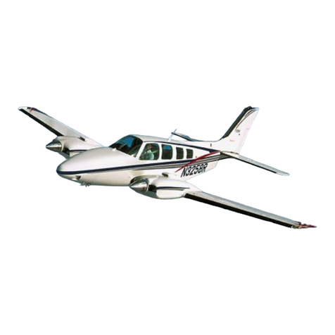
Beechcraft

Beechcraft Pressurized Baron 58PA Quick start guide

Beechcraft Beech 95 2017 Quick setup guide

Beechcraft

Beechcraft Beech 95 2017 Quick setup guide

Beechcraft Turbo-Baron 56TC Install guide
Beechcraft

Beechcraft Turbo-Baron 56TC Install guide

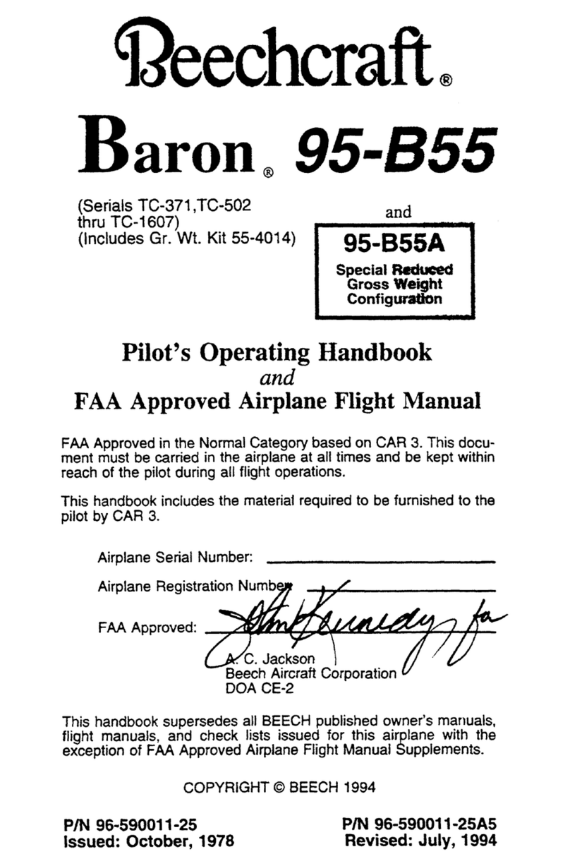
Beechcraft Baron 95-B55 Owner's manual
Beechcraft

Beechcraft Baron 95-B55 Owner's manual

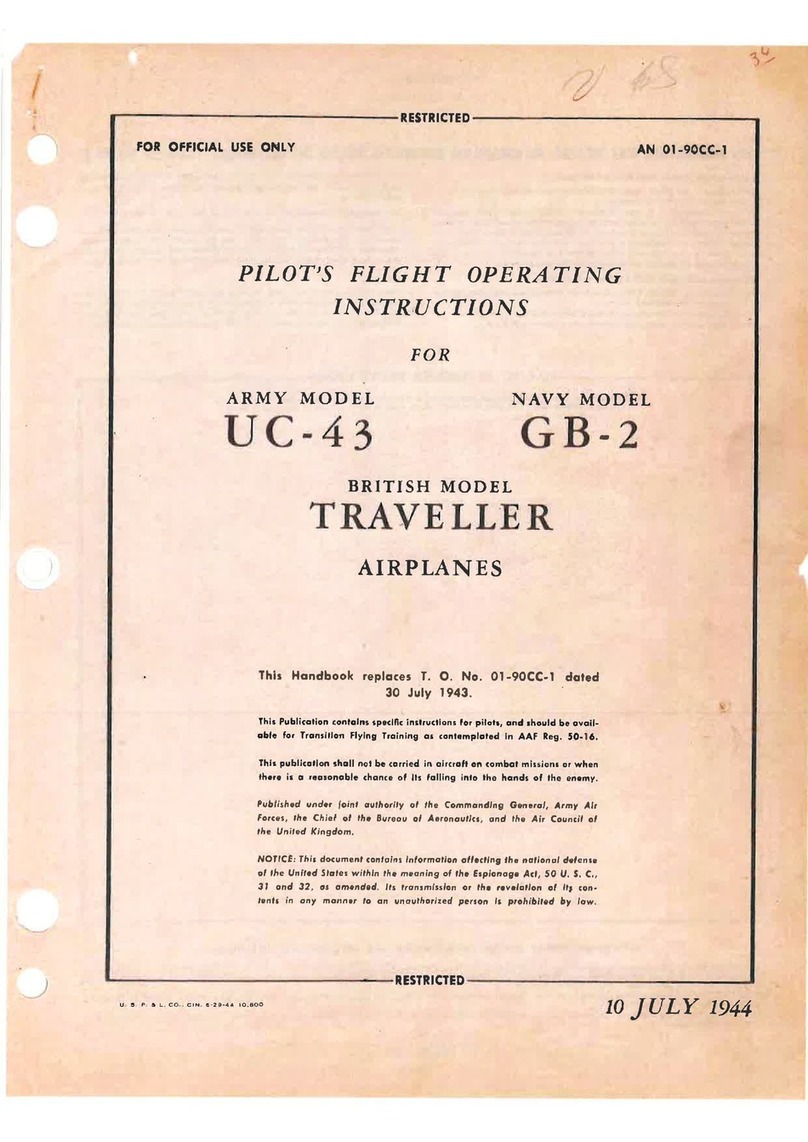
Beechcraft TRAVELLER UC-43 1944 Operating instructions
Beechcraft

Beechcraft TRAVELLER UC-43 1944 Operating instructions

Beechcraft Duchess 76 Technical specifications
Beechcraft

Beechcraft Duchess 76 Technical specifications

Beechcraft Debonair 35-C33 Technical specifications

Beechcraft

Beechcraft Debonair 35-C33 Technical specifications

Popular Tools manuals by other brands

AlzaPower TKE170 user manual

AlzaPower

AlzaPower TKE170 user manual

Ingersoll-Rand 772 Product information

Ingersoll-Rand

Ingersoll-Rand 772 Product information

Makita DHR263 instruction manual

Makita

Makita DHR263 instruction manual

Florida Pneumatic Universal Tool UT8663-TC General Safety Information & Replacement Parts

Florida Pneumatic

Florida Pneumatic Universal Tool UT8663-TC General Safety Information & Replacement Parts

Numa Patriot 180 Care & maintenance instructions

Numa

Numa Patriot 180 Care & maintenance instructions

Simpson PT-22P Operator's manual

Simpson

Simpson PT-22P Operator's manual
SUHNER ABRASIVE LFC 10 Technical document

SUHNER ABRASIVE

SUHNER ABRASIVE LFC 10 Technical document

Power Gear 140-1226 Operation manual

Power Gear

Power Gear 140-1226 Operation manual

Matco Tools MT1815 operating instructions

Matco Tools

Matco Tools MT1815 operating instructions

jbc AM120 instruction manual

jbc

jbc AM120 instruction manual

Nordco CX Operation and maintenance manual

Nordco

Nordco CX Operation and maintenance manual

RIDGID RAPIDOR 120 XF-45 manual

RIDGID

RIDGID RAPIDOR 120 XF-45 manual

Dremel 200 series Original instructions

Dremel

Dremel 200 series Original instructions

SCA 2500KG Hydraulic Owner's instruction manual

SCA

SCA 2500KG Hydraulic Owner's instruction manual

Storch 59 21 40 manual

Storch

Storch 59 21 40 manual

Goodcrafter 939D II instructions

Goodcrafter

Goodcrafter 939D II instructions

WilTec 61202 Operation manual

WilTec

WilTec 61202 Operation manual

Metal Arsenal ECCOTARP ET-ROLLER 5 Assembly and instructions for use

Metal Arsenal

Metal Arsenal ECCOTARP ET-ROLLER 5 Assembly and instructions for use

manuals.online logo
manuals.online logoBrands
  • About & Mission
  • Contact us
  • Privacy Policy
  • Terms and Conditions

Copyright 2025 Manuals.Online. All Rights Reserved.