SCA 2500KG Hydraulic Setup guide


1 2
WARRANTY
This product is guaranteed against defects for a period of 12 months from date of
purchase. This warranty is provided by Super Cheap Auto Pty Ltd ACN 085 395
124 (Supercheap Auto) of 751 Gympie Rd Lawnton QLD 4501 Ph (07) 3482 7500.
Supercheap Auto will offer a repair, replacement product or store credit if the product
is assessed as being defective during the warranty period.
To claim under this warranty, take this product to the Front Service Desk of your nearest
Supercheap Auto store. For store locations, visit www.supercheapauto.com.au (AUS)
or www.supercheapauto.co.nz (NZ). You will need your receipt or proof of purchase.
Additional information may be requested of you to process your claim. Should you not
be able to provide proof of purchase with a receipt or a bank statement, identification
showing your name, address and signature may be required to process your claim.
This product may need to be sent to the manufacturer to assess the defect before
determining any claim. Faults or defects caused by product modification, misuse and
abuse, normal wear and tear or failure to follow user instructions are not covered
under this warranty.
Our goods come with guarantees that cannot be excluded under the Australian
Consumer Law. You are entitled to a replacement or refund for a major failure and
for compensation for any other reasonably foreseeable loss or damage. You are also
entitled to have the goods repaired or replaced if the goods fail to be of acceptable
quality and the failure does not amount to a major failure.
Any expenses incurred relating to the return of this product to store will normally have
to be paid by you. For more information contact your nearest Supercheap Auto store.
The benefits to the consumer given by this warranty are in addition to other rights and
remedies of the Australian Consumer Law in relation to the goods and services to
which this warranty relates.
WARNING
ASSEMBLY INSTRUCTION
• The hydraulic trolley jack should be used on a hard level surface and be free to roll
during lifting and lowering.
• The unlifted wheels of the vehicle should be chocked.
• The load should be centrally located on the head cap.
• No person should remain in a vehicle that is being lifted.
• The hydraulic trolley jack should be used for lifting and lowering only; the raised
vehicle should be supported on vehicle support stands.
• No person should get bodily under a vehicle that is supported only by a hydraulic
trolley jack.
• The vehicle manufacturer owner’s manual should be consulted prior to the lifting
of the vehicle.
TO ASSEMBLE THE JACK FOR USE:
1. Screw together the 3 parts of the handle.
2. Insert the assembled handle into handle socket
on the jack.
3. Secure the handle to the jack with the bolt
provided.
SPECIFICATIONS
Working Load Limit: 2500kg
Jack Dimensions: 625mm x 345mm x 265mm
Height Lowered: 130mm
Height Raised: 480mm
This hydraulic trolley jack is designed to be used
with a 110mm diameter head cap, and a handle
length of 1490mm length.

3 4
SAFETY INSTRUCTIONS & OPERATION
INSPECTION:
1. Before each use a visual inspection of the jack should be made. This should
check for things such as cracks in the welds, leaking oil, any general damage, and
loose or missing parts.
2. An annual inspection of the jack is recommended.
3. Do not use if any damage evident.
CAUTION BEFORE USE:
Lubricate all pivoting and moving points - see LUBRICATION on Page 5.
Occasionally during shipment and/or handling, air can become trapped in the
hydraulic system.
This can interfere with the jacks lifting performance. To alleviate this problem:
1. Ensure the jack is in lowered position. Open the release valve by turning the jack
handle anti-clockwise.
2. Rapidly pump the jack handle several times.
3. Open the air vent by removing the filler plug on the oil chamber.
4. Replace the filler plug. This process may need to be repeated several times to
purge all air out of the hydraulic system.
TO RAISE THE JACK:
1. Close the release valve by turning the jack handle clockwise until the release
valve is closed. Do not over tighten the valve.
2. Chock the wheels of the car with appropriate devices (e.g. Automotive wheel
chocks). This will help ensure that the vehicle will remain stable during lifting.
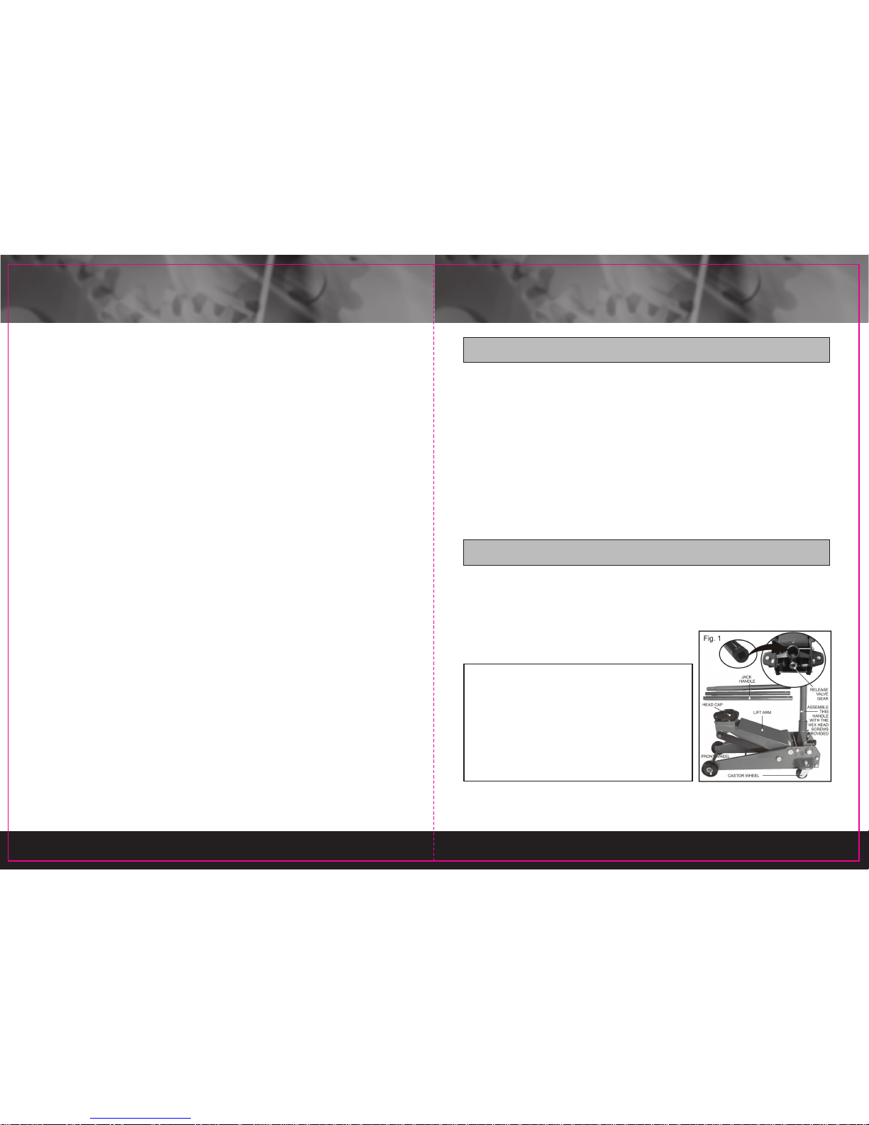
3. Place the jack so the head cap on the lifting arm is directly under the object to
be lifted. Please refer to the vehicle manufacturer owner’s manual to locate
approved lifting points on the vehicle.
4. Pump the jack handle until the head cap is almost in contact with the vehicle.
Check that the head cap will be centrally located at the vehicle manufacturers
recommended lifting point.
5. Continue to pump the jack handle to lift the vehicle to the desired height.
6. After lifting the vehicle to the desired height, support the load with approved
vehicle support stands before working under the vehicle.
TO LOWER THE JACK:
1. With the jack supporting the weight of the vehicle, remove the vehicle support
stands.
2. Very slowly turn the jack handle anti-clockwise.
This will open the release valve and when the release valve starts to open, the
lifting arm will lower.
3. The speed which the jack will lower, will be dependent on how rapidly the valve is
opened.
The greater it is opened the faster the jack will lower.
CAUTION:
Ensure all hands, feet and all other items are well clear of the ground area when
lowering the load.
MAINTENANCE
OIL TYPE:
IMPORTANT: When adding or replacing oil, always use a good grade of HYDRAU-
LIC FLUID. (Recommended ISO VG32, SAE10 or equivalent) Avoid mixing types of
fluid. DO NOT use Brake Fluid, Alcohol, Glycerine, Detergent, Motor Oil or Dirty Oil.
ADDING OIL & OIL LEVEL:
1. Set the jack in a horizontal level position and fully lower the head cap. Remove
the screw-in filler plug on the oil chamber (Fig. 2).
2. Fill using oil can with a fine spout. The recommended oil capacity is
approximately 190ml. If low, add oil as required.
3. Replace the screw-in filler plug on the oil chamber.

5 6
REPLACING OIL:
1. Remove the screw-in filler plug on the oil chamber.
2. Turn the jack upside down and drain the old oil out through the hole of the oil
chamber (Fig. 2).
3. Fill the jack with new oil through the hole of the oil chamber.
Do not allow any dirt or other foreign material to enter the hydraulic system when
re-filling.
After Re-filling the jack oil, remove any air from the hydraulic system (please refer
to caution on page 3 before use)
LUBRICATION:
Lubricate all pivoting and moving points with lubricating oil prior to initial use and
after every 20 lifting/lowering cycles or 3 months (whichever occurs first)
RUST PREVENTION & STORAGE:
1. Check jack every few months for any signs of rust or corrosion. Clean as needed
by wiping with an oily cloth.
2. When not in use, always store jack with wheels on horizontal surface and with
lifting arm lowered all the way.
TROUBLE SHOOTING
POSSIBLE PROBLEMS POSSIBLE CAUSES
AND SOLUTIONS
(Refer to operation and
maintenance procedures
for detailed information)
Jack
will
not lift
load
Jack
will lift
load,
but will
not hold
Jack will
not lower
completely
Poor jack
lifting.
Pump feels
spongy
Jack
will
not lift
to full
height
Handle
raises by
itself when
jack is under
load
X
Ensure that handle has
been turned clockwise to
a point at which it is firm/
tight.
X X X X
Air is in hydraulic
system.
Release air from system.
X X X X Oil level is low in jack.
Add oil as required.
X
1. Oil reservoir is
over-filled.
Drain out some oil.
2. Lubrication of all
pivoting and moving
parts is necessary.

7 8
PARTS LIST Ref. No. Qty. Description Ref. No. Qty. Description
11 Main Frame 22 1 Handle, Middle
22 Front Wheel 23 1Handle, Upper
32Flat Washer 24 1 Handle, Lower
42Retaining Ring 25 1Short Bolt For Handle Socket
52 Link Rod 26 3Reforcing spindle
61Head Cap 27
7
Spring Washer
71Lift Arm Assembly 28 7Nut
81 Grease Nipple 29 2 Spring Washer
92 Retaining Ring 30 2 Socket Head Screw
10 1 Ram Connecting Rod 31 2 Rear Castor Wheel
11 1 Cotter Pin 32 2 Nut
12 1 Spring 33 2 Spring Washer
13 1 Hydraulic Ram Assembly 34 2 Bolt For Link Rod
14 1 Long Bolt For Handle Socket 35 2 Hex Head Screw
15 2 Spring Washer 36 2 Retaining Ring
16 1 Torsion Spring 37 1 Lift Arm Shaft
17 1 Handle Socket 38 1 Safety Valve Cover
18 1 Handle Screw 39 2 Bushing
19 1 Gear 40 2 C Clip
20 1 Cotter Pin 41 2 Spring
21 1 Gear Shaft 42 2 Lock Nut
Table of contents