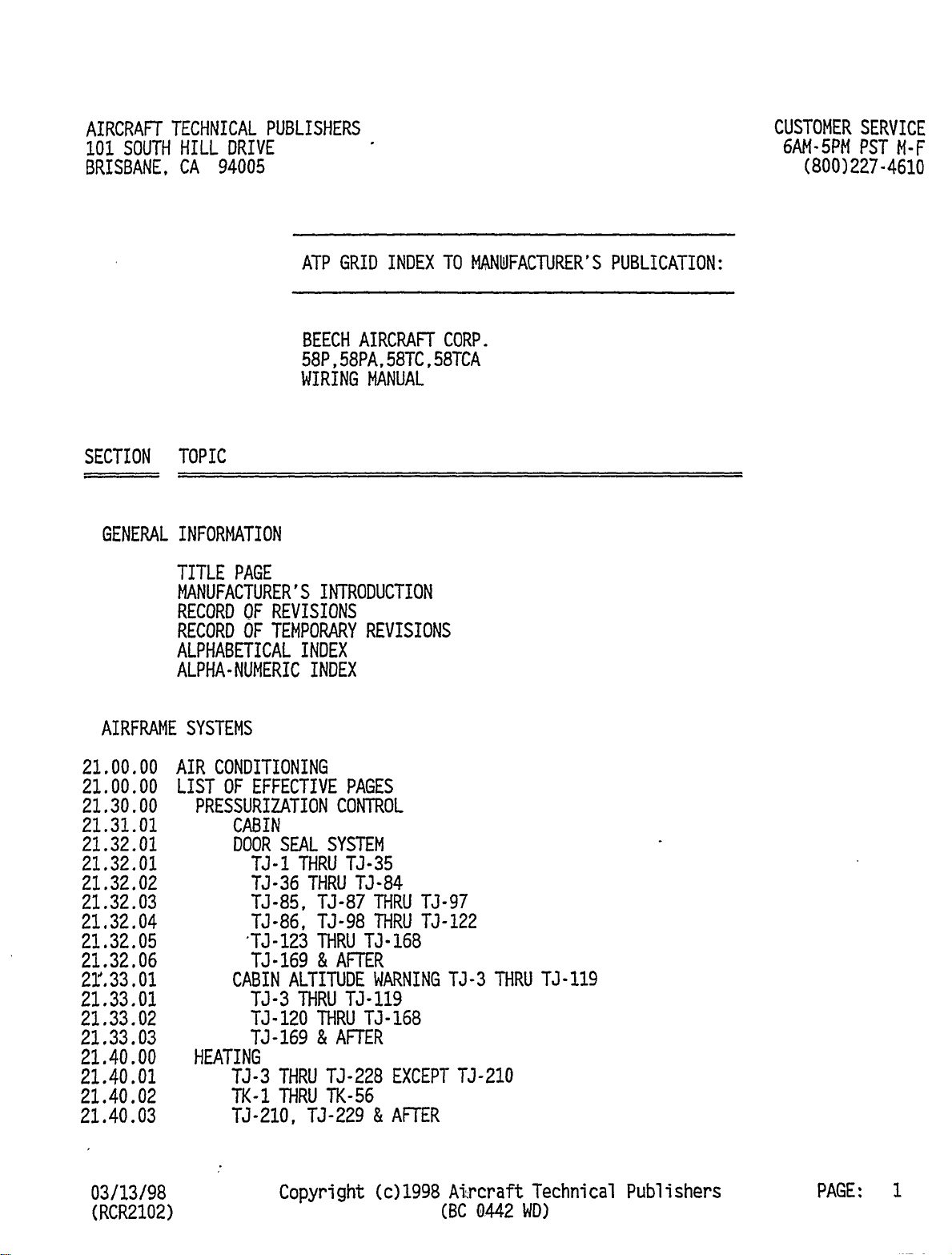
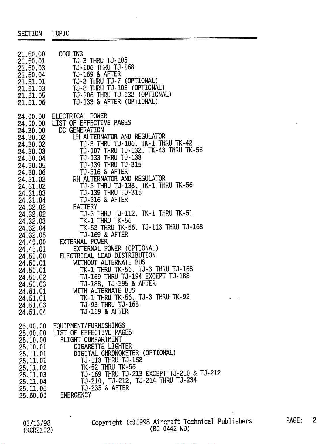
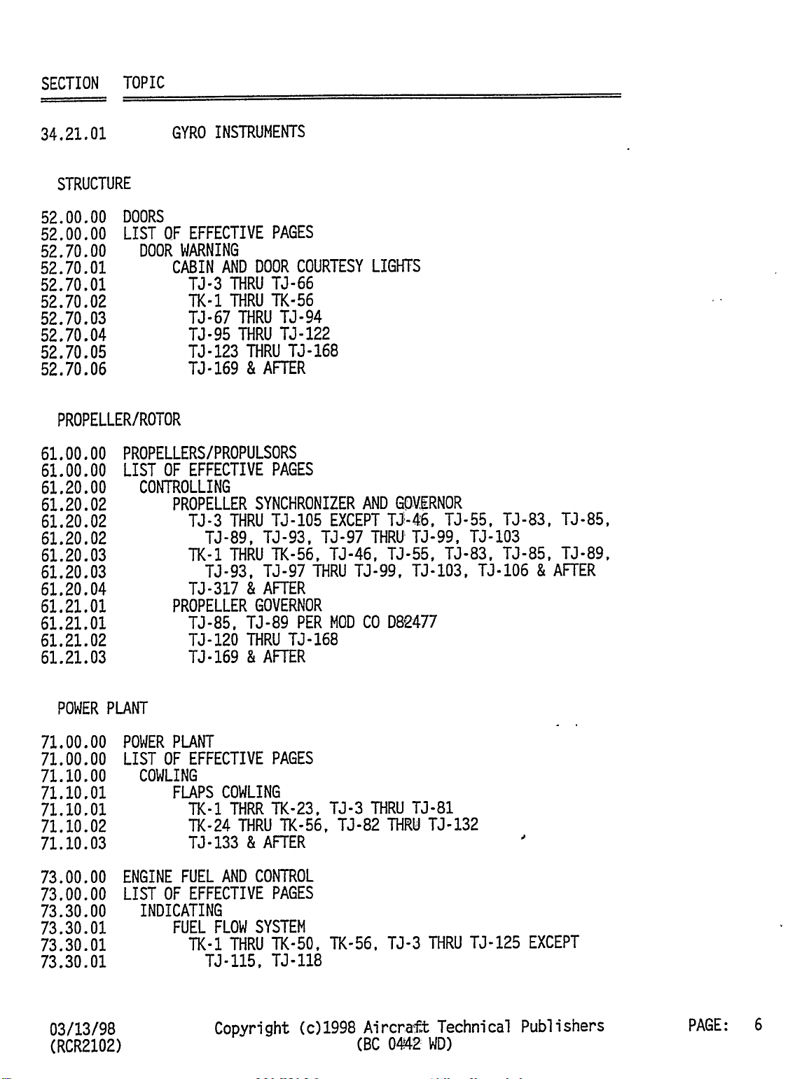
Beechcraft Pressurized Baron 58PA Quick start guide

ATP
INDEX
COPYRIGHT 2002
COPYRIGHT IS NOT CLAIMED AS TO ANY PART OF AN ORIGINAL WORK
PREPARED BY A UNITED STATES GOVERNMENT OFFICER OR EMPLOYEE AS
PART OF THAT PERSONS OFFICIAL DUTIES OR BY ANY OTHER THIRD PARTY
OFFICER OR EMPLOYEE AS PART OF THAT PERSONS DUTIES.
"ATP" is a registered trademark of Aircraft Technical Publishers. All original
authorship of ATP is protected under U.S. and foreign copyrights and is subject
to written license agreements between ATP and its Subscribers.
ALL RIGHTS RESERVED. NO PART OF THIS PUBLICATION MAY BE
REPRODUCED, STORED IN A RETRIEVAL SYSTEM, OR TRANSMITTED IN ANY
FORM BY ANY MEANS, ELECTRONIC, MECHANICAL, PHOTOCOPYING,
RECORDING OR OTHERWISE, WITHOUT PRIOR WRITTEN PERMISSION OF THE
PUBLISHER.

AIRCRAFT
TECHNICAL
PUBLISHERS
CUSTOMER
SERVICE
101
SOUTH
HILL
DRIVE
6AM-
5PM
PST
M-F
BRISBANE,
CA
94005
(800)227-4610
ATP
GRID
INDEX
TO
MANUFACTURER’S
PUBLICATION:
BEECH
AIRCRAFT
CORP.
58P,58PA,58TC,58TCA
WIRING
MANUAL
SECTION
TOPIC
GENERAL
INFORMATION
TITLE
PAGE
MANUFACTURER’S
INTRODUCTION
RECORD
OF
REVISIONS
RECORD
OF
TEMPORARY
REVISIONS
ALPHABETICAL
INDEX
ALPHA-NUMERIC
INDEX
AIRFRAME
SYSTEMS
21.00.00
AIR
CONDITIONING
21.00.00
LIST
OF
EFFECTIVE
PAGES
21.30.00
PRESSURIZATION
CONTROL
21.31.01
CABIN
21.32.01
DOOR
SEAL
SYSTEM
21.32.01
TJ-l
THRU
TJ-35
21.32.02
TJ-36
THRU
T3-84
21.32.03
TJ-85,
TJ-87
THRU
T3-97
21,32.04
TJ-86,
TJ-98
THRU
TJ-122
21.32.05
’TJ-123
THRU
TJ-168
21.32.06
TJ-169
AFTER
22".33.01
CABIN
ALTITUDE
WARNING
T3-3
MRU
T3-119
21.33.01
T3-3
MRU
TJ-119
21.33.02
TJ-120
THRU
T3-168
21.33.03
TJ-169
AFTER
21.40.00
HEATING
21.40.01
TJ-3
THRU
TJ-228
EXCEPT
TJ-210
21.40.02
TK-1
THRU
TK-56
21.40.03
TJ-210,
TJ-229
AFTER
03/13/98
Copyrigh’e
(c)1998
Ai:rcraf~t;
Technical
Publishers
PAGE:
1
(RCR2102)
(BC
0442
WD)

SECTION
TOPIC
21.50.00
COOLING
21.50.01
TJ-3
THRU
T3-105
21.50,03
TJ-106
THRU
TJ-168
21.50.04
T3-169
AFTER
21.51.01
TJ-3
THRU
TJ-7
(OPTIONAL)
21.51.03
T3-8
THRU
TJ-105
(OPTIONAL)
21.51.05
TJ´•106
MRU
TJ-132
(OPTIONAL)
21.51.06
TJ-133
AFTER
(OPTIONAL)
24.00.00
ELECTRICAL
POWER
24.00.00
LIST
OF
EFFECTIVE
PAGES
24.30.00
DC
GENERATION
24.30.02
LH
ALTERNATOR
AND
REGULATOR
24.30.02
TJ-3
THRU
TJ-106,
TK-1
THRU
TK-42
24,30.03
TJ-107
THRU
TJ-132,
TK-43
THRU
TK-56
24.30.04
TJ-133
MRU
TJ-138
24.30.05
T3-139
MRU
TJ-315
24.30.06
TJ-316
AFTER
24.31.02
RH
ALTERNATOR
AND
REGULATOR
24,31.02
TJ-3
THRU
TJ-138,
TK-1
MRU
TK-56
24.31.03
TJ-139
THRU
T3-315
24.31.04
TJ-316
AFTER
24.32.02
BATTERY
24.32.02
TJ-3
MRU
T3-112,
TK-1
THRU
TK-51
24.32.03
TK-1
THRU
TK-56
24.32.04
TK-52
MRU
TK-56,
TJ-113
THRU
TJ-168
24.32.05
T3-169
AFTER
24.40.00
EXTERNAL
POWER
24.41.01
EXTERNAL
POWER
(OPTIONAL)
24.50.00
ELECTRICAL
LOAD
DISTRIBUTION
24,50.01
WITHOUT
ALTERNATE
BUS
24.50.01
TK-1
THRU
TK-56,
TJ-3
THRU
TJ-168
24.50.02
TJ-169
THRU
TJ-194
EXCEPT
T3-188
24.50.03
TJ-188,
T3-195
AFTER
24.51.01
WITH
ALTERNATE
BUS
24.51.01
TK-1
MRU
TK-56,
TJ-3
MRU´•
TK-92
24.51.03
TJ-93
THRU
TJ-168
24.51.04
TJ-169
AFTER
25.00.00
EQUIPMENT/FURNISHINGS
25.00.00
LIST
OF
EFFECTIVE
PAGES
25.10.00
FLIGHT
COMPARTMEKT
25.10.01
CIGARETTE
LIGHTER
25.11.01
DIGITAL
CHRONOMETER
(OPTIONAL)
25.11.01
TJ-113
THRU
13-168
25,11.02
TK-52
THRU
TK-56
25.11,03
TJ-169
THRU
TJ-213
EXCEPT
TJ-210
TJ-212
25.11.04
T3-210,
TJ-212,
TJ-214
THRU
TJ-234
25.13..05
13-235
AFTER
25.60.00
EMERGENCY
03/13/98
Copyright
(c)1398
Aircraft
Technical
Publishers
PAGE:
2
(RCR2102)
(BC
0442
WD)

SECTION
TOPIC
25.60.01
EMERGENCY
LOCATOR
TRANSMITTER
27.00.00
FLIGHT
CONTROLS
27.00.00
LIST
OF
EFFECTIVE
PAGES
27.30.00
ELEVATOR
AND
TAB
27.31.01
STALL
WARNING
(WITH
HEATER)
27.31.01
TK-1
MRU
TK-39,
TJ-3
THR~
TJ-97
27.31.02
TK-40
THRU
TK-56,
TJ-98
T~RU
TJ-121
27.31.03
TJ-122
AFTER
27.32.01
ELEVATOR
TRIM
(OPTIONAL)
27.50.00
FLAPS
27.50.01
MOTOR
27.50.02
PERMANENT
MAGNET
MOTOR
27.50.02
TK-43
THRU
TK-56,
T3-107
THRU
TJ-126
27,50.03
TJ-127
THRU
TJ-134
27.50.04
TJ-135
’THRU
TJ-186
27.50.05
TJ-187
AFTER
27.51.01
POSITION
INDICATOR
27.51.01
TJ-3
MRU
T3-186,
TK-1
THRU
TK-55
27.51.02
TJ-187
AFTER
28.00.00
FUEL
28.00.00
LIST
OF
EFFECTIVE
PAGES
28,10.00
STORAGE
28.10.01
FUEL
VENT
HEATERS
28,20.00
DISTRIBUTION
28.20.01
FUEL
BOOST
PUMP
28.20.01
TK-1
THRU
TK-56,
TJ-3
THRLI
TJ-168
28.20.02
TJ-169
THRU
T3-223
28.20.03
TJ-224
AFTER
28.40.00
INDICATING
28,40.01
FUEL
QUAKTITY
28,40.01
T3-3
THRU
TJ-27
28,40.02
TJ-28
AFTER,
TK-I
THRU
TK-56
28.40.03
T3-368
AFTER
30.00.00
ICE
AND
RAIN
PROTECTION
30.00.00
LIST
OF
EFFECTIVE
PAGES
30.10.00
AIRFOIL
30.10.01
SURFACE
DEICE
(OPTIONAL)
30.10.01
7;7-3
T3-4
30.10.03
TJ-5
THRU
TJ-97
EXCEPT
T3-86,
TK-I
THRU
TK-56
30.10,04
TJ-3,
TJ-86,
T3-98
THRU
T3-316
30.10.05
TJ-317
AFTER
30,30.00
PITOT
AND
STATIC
30.30.01
HEAT
30.40.00
WINDOWS,
WINDSHIELDS,
AND
DOORS
30.40.01
WINDSHIELD
ANTI-ICE
(OPTIOM;I\L)
30.41.01
WINDSHIELD
ALCOHOL
30.42.01
WINDSHIELD
ELECTROTHERMAL
ANTI-ICE
03/13/98
Copyright
tc)1998
AircPaft
Technica~
Publishers
PAGE:
3
(RCR2102)
(8C
0442
WD)

SECTION
TOPIC
30.60.00
PROPELLERS/ROTORS
30.61..01
3
BLADE
DEICE
30.61.02
3
BLADE
ANTI-ICE
(OPTIONAL)
30.61.02
T3-l1
MRU
T3-176
EXCEPT
TJ-174,
TK-1
THRU
TK-56
30.61.03
TJ-174,
T3-177
THRU
7;1-348
30.61.04
T3-349
AT~R
31.00.00
INDICATING/RECORDING
SYSTEMS
31.00.00
LIST
OF
EFFECTIVE
PAGES
31.30.00
RECORDERS
31.30.01
FLIGHT
HOUR
METER
(OPTIONAL)
31.31.01
ENGINE
HOUR
METER
(OPTIONAL)
31.50.00
CENTRAL
WARNING
SYSTEMS
32.51.01
GWIESHIELD
ANNUNCIATOR
31.51.01
TJ-169
THRU
TJ-316
31.51.02
T3-317
AFTER
31.52.01
GLARESHIELD
ANNUNCIATOR
LIGHT
TEST
31.52.01
T3-169
MRU
TJ-316
31.52.02
TJ-317
AFTER
32.00.00
LANDING
GEAR
32.00.00
LIST
OF
EFFECTIVE
PAGES
32.30.00
EXTENSION
AND
RETRACTION
32,30.02
LANDING
GEAR
MOTOR
AND
RELAY
32.30.02
TK-1
THRU
TK-56,
TJ-3
THRU
TJ-132
32.30.03
TJ-133
AFTER
32.31,01
LANDING
GEAR
POSITION
INDICA~R
32.31,01
TK-1
THRUT
TK-56,
TJ-3
THRU
TJ-132
32.31.02
TJ-133
MRU
TJ-168
32.31.03
TJ-169
AFTER
32.60.00
POSITION
AND
WARNING
32.60.01
THROTTLE
32.60.01
TK-1
THRU
TK-56
TJ-3
THRU
TJ-133
32.60.02
T3-134
AND
AFTER
33.00.00
LIGHTS
33,00.00
LIST
OF
EFFECTIVE
PAGES
33.10.00
FLIGHT
COMPARTMENT
33.10.01
ANNUNCIATOR
LIGHT
TEST
33,10.01
TK-1
TO
TK-56,TJ-3
TO
-97
EXCEPT
-46,-55,-83,-86,-89
33.10.02
TK-1,
TK-9
MRU
TK-56,TJ-4~6,T3-55,TJ-83,TJ-85,TJ-89
33.10.03
TJ-86,
T3-98
THRU
TJ-119
33.10~04
TJ-120
THRU
TJ-168
33.11.01
MAP,
COMPASS,
OAT
AND
WHEEL
CLOCK
LIGHTS
33.11.01
TK-1
THRU
TK-56,
TJ-3
MRUIT;3-92
33.11.02
TJ-93
THRU
TJ-116
33.11.03
TJ-117
THRU
TJ-209,
T3-211,
TJ-213
33,11.04
TJ-210,TJ-212,
TJ-214
XI
AF71ER
33,12.01
ENGINE
INSTRUMENT
AND
RADIO
~BGKTS
33.12.01
TK-1
THRU
TK-56,
TJ-3
THRU!
T5-92
03/13/98
Copyright
(c)1998
Technical
Publishers
PAGE:
4
(RCR2102)
(BC
WD)

SECTION
TOPIC
33.12.02
TJ-93
THRU
TJ-134
33.12.03
TJ-135
8
AFTER
33.13.01
ENGINE
INSTRUMENT
AND
RADIO
POST
LIGHTS
33,13.02
11;3-263
AND
AFTER
33.14.01
ENGINE
INSTRUMENT
AND
RADIO´•
WEDGE
LIGHTS
33.14.02
TJ-263
AND
AFTER
33,15.01
FLIGHT
INSTRUMENT
LIGHTS
33.15.01
TK-1
THRU
TK-56,
TJ-3
THRU
T3-92
33,25.02
T3-93
AFTER
33.16.01
FLIGHT
INSTRUMENT
POST
LIGHTS
33.16.02
T3-263
8
AFTER
33.17.01
FLIGHT
INSTRUMENT
WEDGE
LIGHTS
33.17.02
T3-263
8
AFTER
33.18.01
FLOODLIGHTS
33.18.01
TK-1
THRU
TK-56,
TJ-3
THRU
TJ-92
33.18.02
TJ-93
THRU
TJ-129
33.18.03
TJ-130
8
AFTER
33.19.01
ELECTROLUMINESCENT
PANEL
LIGHTS
33.19.01
TK-1
THRU
TK-56,
TJ-3
MF~
TJ-92
33.19.02
TJ-93
8
AFTER
33.20.00
PASSENGER
COMPARTMENT
33.20.01
CABIN
LIGHTS
33.20.01
TK-1
THRU
TK-56,
TJ-3
THRU
TK-92
33.20.02
TJ-93
MRU
TJ-122
33.20,03
T3-123
8
AFTER
33.30.00
CARGO
AND
SERVICE
COMPARTMENTS
33.30.01
BAGGAGE
COMPARTMENT
LIGHTS
33.40.00
EXTERIOR
33.40.01
THREE
LIGHT
STROBE
33.40.01
TK-1
MRU
TK-19,
TJ-3
THRU
TJ-79
33.40.02
TK-20
MRU
TK-56,
7;3-80
THRU
TJ-132
33.40.03
T3-133
8
AFTER
33.43.01
TAXI
LIGHT
33.44.01
ROTATING
BEACON
33.44.01
TK-1,
T3-3
MRU
T3-53
33.44.02
TK-2
THRU
TK-56,
TJ-54
8
AFTER
33.45.01
NAVIGATION
LIGHTS
33.45.01
TK-1
THRU
TK-56,
T3-3
THF~´•
TJ-132
33,45.02
TJ-133
8
AFTER
33.46.01
LANDING
LIGHTS
33.46.01
TK-1
MRU
TK-28,
TJ-3
MRU
TJ-93
33.46.02
TK-29
MRU
TK-56,
TJ-94
8;
AFTER
33.47.01
ICE
LIGHTS
34.00.00
NAVIGATION
34.00.00
LIST
OF
EFFECTIVE
PAGES
34.20.00
ATTITUDE
AND
DIRECTION
34.20.01
TURN
AND
SLIP
COORDINATOR
34.20.01
TK-1
THRU
TK-56,
TJ-3
THRU
TJ-92
34.20.02
TJ-93
8
AFTER
03/13/98
Copyright
(c)1998
Aircra.ft
Technical
Publishers
PAGE:
5
(RCR2102)
(BC
0’442
WD)

SECTION
TOPIC
34.21,01
GYRO
INSTRUMENTS
STRUCTURE
52.00.00
DOORS
52.00.00
LIST
OF
EFFECTIVE
PAGES
52.70.00
DOOR
WARNING
52.70.01
CABIN
AND
DOOR
COURTESY
LIGHTS
52.70.01
7;3-3
THRU
TJ-66
52.70.02
TK-1
THRU
TK-56
52.70.03
TJ-67
MRU
TJ-94
52,70.04
TJ-95
THRU
T3-122
52.70.05
TJ-123
MRU
TJ-168
52.70.06
TJ-169
AFTER
PROPELLER/ROTOR
61.00.00
PROPELLERS/PROPULSORS
61.00.00
LIST
OF
EFFECTIVE
PAGES
61.20.00
CONTROLLING
61.20.02
PROPELLER
SYNCHRONIZER
AND
GOVERNOR
61.20.02
TJ-3
THRU
TJ-105
EXCEPT
T3-46,
T3-55,
T3-83,
TJ-85,
61.20.02
TJ-89,TJ-93,
TJ-97
MRVTJ-99,
TJ-103
61.20.03
TK-1
MRU
TK-56,
TJ-46,
TJ-56,
TJ-83,
T3-85,
TJ-89,
61.20.03
TJ-93,
TJ-97
MRU
T3-99,
TJ-103,
TJ-106
AFTER
61.20.04
TJ-317
AFTER
61.21.01
PROPELLER
GOVERNOR
61.21.01
T3-85,
TJ-89
PER
MOD
CO
D8´•2477
61.21.02
T3-120
THRU
TJ-168
61.21.03
T3-169
AFTER
POWER
PLANT
71.00.00
POWER
PLANT
71.00.00
LIST
OF
EFFECTIVE
PAGES
71.10.00
COWLING
71,10.01
FLAPS
COWLING
71.10.01
TK-1
THRR
TK-23,
TJ-3
MRU
TJ-81
71.10.02
TK-24
THRU
TK-56,
T3-82
THRM
T3-132
71.10.03
TJ-133
AFTER
73.00.00
ENGINE FUEL
AND
CONTROL
73.00.00
LIST
OF
EFFECTIVE
PAGES
73.30.00
INDICATING
73.30.01
FUEL
FLOW
SYSTEM
73.30.01
TK-1
MRU
TK-50,
TK-56,
TJ-3
THRU
TJ-125
EXCEPT
73.30.01
TJ-115,
TJ-118
03/13/98
Copyright
(c)1998
Aircrsft
Technical
Publishers
PAGE:
6
(RCR2102)
(BC
WD)

SECTION
TOPIC
73.30.02
TK-51
THRU
TK-55,
TJ-115
TMRU
TJ-118,
7;3-126
AFTER
73.30.03
TJ-286
AFTER
74,00.00
IGNITION
74.00.00
LIST
OF
EFFECTIVE
PAGES
74.30.00
SWITCHING
74.30.01
IGNITION
SWITCHING
77.00.00
ENGINE
INDICATING
77.00.00
LIST
OF
EFFECTIVE
PAGES
77.10.00
POWER
77.10.01
TACHOMETER
77.20.00
TEMPERATURE
77.20.01
RIGHT
CYLINDER
HEAD
AND
OIL
77.21.01
LEFT
CYLINDER
HEAD
AND
OIL
78.00.00
EXHAUST
78.00.00
LIST
OF
EFFECTIVE
PAGES
78.40.00
SUPPLEMENTARY
AIR
78.40.01
TURBINE
INLET
TEMPERATURE,
ENGINE
INDICATING
91.00.00
CHARTS
91.00.00
LIST
OF
EFFECTIVE
PAGES
91.01.01
BOX
ASSEMBLY
ANNUNCIATOR
PC
BOARD
SCHEMATIC
91.10.01
CONNECTOR
NOSE
ACCESS
91.10.01
TJ-3
THRU
TJ-7
91.10.02
T3-8
THRU
TJ-228
EXCEPT
T3-u0,
TK-1
THRU
TK-56
91.10.03
TJ-21O,
TJ-229
AFTER
91.11.02
CONNECTOR
LH
WING
ACCESS
91.11.02
TK-1
THRU
TK-42,
TJ-3
THRU
T3-106
91.11.03
TK-43
THRU
TK-56,
T3-107
THRU
TJ-132
91.11.04
TJ-133
AFTER
91.12.01
TK-1
THRU
TK-56,
TJ-3
THRU
TJ-132
91.12.02
T3-133
AFTER
91.13.01
CONNECTOR
LH
ENGINE
ACCESS
91.13.01
TJ-3
MRU
T3-7
91.13.02
TJ-8
THRU
TJ-114,
TJ-119
T1RU
TJ-125,
91.13.02
TK-1
THRU
TK-50,
TK-56
91.13.03
TK-51
THRU
TK-55,
TJ-115
THRU
T3-118,
TJ-126,
TJ-132
91.13.04
T3-133
AFTER
91.14.02
TK-1
THRU
TK-56,
TJ-3
THRU
T3-132
91.15.02
CONNECTOR
RH
WING
ACCESS
91.15.02’
TK-1
THRU
TK-56,
TJ-3
THRU
13-132
91.15.03
TJ-133
AFTER
91.16.02
CONNECTOR
RH
ENGINE
ACCESS
91.16.02
TK-1
THRU
TK-56,
TJ-3
THRU
TJ-132,
TJ-119
THRU
TJ-125
91.16.03
TK-51
THRU
55
TJ´•115
M~
TJ-118
TJ-126
AFT
91.17.01
TK-1
MRU
TK-56
T3-3
T3-132
91.18.01
CONNECTOR
AFT
FUSELAGE
91.18.01
TK-1
THRU
TK-56
TJ-3
M~
T3-132
03/13/98
Copyright
(c)1998
Aircra~ft
Technical
Publishers
PAGE:
7
(RCR2102)
(BC
0’44´•2
WD)

SECTION
TOPIC
91.18.02
TK-133
AND
AFTER
91.19.01
CONNECTOR
INSTRUMENT
PANEL
GROUNDING
91.20.01
CONNECTOR
FLOATING
PANEL
DISCONNECT
91.21.01
CONNECTOR
GLARESHIELD
91.22.01
CONNECTOR
FLOATING
PANEL
DISCONNECT
91.22.01
TJ-120
MRU
TJ-166
91.22.02
TJ-169
AND
AFTER
91.23,01
CONNECTOR
GWUZSHIELD
ANNUNCIATOR
91.23.01
TJ-169
MRU
TJ-316
91.23.02
TJ-317
AND
AFTER
91.24.01
TJ-169
AND
AFTER
j’~
END
OF
INDEX
’´•it~’
03/13/98
Copyright
(c)1998
Aircraft
Technical
Publishers
PAGE:
8
(RCR2102)
(BC
t~)

NI
FG.
INTRO

Caeechaaft
PRESSURIZED
TURBOCHARGED
Ci~ron
(i~t-on
56P
58PA
S8TC
58TCA
SERIALS
TJ-3
AND
AFTER
SERIALS
TK-I
’THRU
TK-56
G:
VVIRING~
DI~AGRAM.
COPYRIGHI
BEECH
1981
PIN
102-590000-233
Reissued:
July
3,
1981

PUBLISHED
BY
COMMERCIAL
PRO~CT
SUPPORT
BEECH
AIRCRAFT
CORPORATION
WICHITA,
KANSi9S
61201
U.
S.
A.
M´•mb´•rofG1MA
’1~
G´•n´•rolAvio~ion
A
Raytheon
Company
~I
Manufactur´•nAlrod~tion

RECORD
OF
REVISIONS
MFG
REV
NO
DESCRIPTION
ISSUEDATE
ATPREVDA‘
INSERTED
BY
E
IReissue
7/3/81
3/23/98
ATP/IM

LIST
OF
EFFECTIVE
REVISION~
AIways
destroy
superseded
pages
when
you
insert
revised
pages.
Title
Page
........................................July
3,
1981
Logo
Page´•´•´•´•´•´•´•´•´•´•´•´•´•´•´•´•´•..............................,......
"A"
Page.
....July
3,
1981
LOG
OF
REVISIONS
Part
Number
Date
Chapters
Affected
102-590000-23
July
19,
1974
ORIGINAL
ISSUE
102-590000-23B
January
30,
1976
REISSUED
102-590000-23C
Rebruary
3,
1978
REISSUED
102-590000-23D
October
28,
1979
REISSUED
102-590000-233
July
3,
1981
REISSUED
E
NOTE:
A
list
of
the
effective
pages
will
be
found
in
the
front
of
each
chapter.
basic
publications
are
assigned
a
part
number
which
appears
on
the
title
page
with
the
date
of
the
issue.
subsequent
revisions
are
identified
by
the
adGilion
ofa
revision
code
after
the
part
number.
Al
after
a
part
number
denotes,thq
first
revision
to
the
basic
publication.
A2
me
second.
etc.
Occasionally,
it
is
necessary
to
completely
reissue
and
reprint
a
publication
for
the
purpose
of
a
previous
issue
and
outstanding
renuons
thereto.
As
these
replacement
reissues
are
made.
the
code
will
also
change
to
the
next
successive
letter
of
tl;e
alphabet
It
each
issue.
For
example.
B
for
the
rrrstreissue.
C
for
the
second
reissue.
etc.
When
ordering
a
handbook.
~ve
the
basic
number,
and
the
reissue
code
when
applicable,
ifa
complete
upto~ale
publication
is
desired.
Should
only
revision
pager
be
required,
give
the
basic
number
and
revision
code
lot
the
particular
set
of
revision
pages
you
desire.

RECORD
Of
TEMPO~RARY
REVISIONS
AF~
P
ATP
REV
INSERT
DATE
REV
REMOVE
Rn/
NO
DESCRIPTION
ISSUE
DATE
1I~4TE
BY
REMOVED
INCOR
BY

BEECHCRAFT
BARON
58g
ANB
BARON
58TC
WIRING
dl~iRAM
~IANUAL
IIUTRODUCTION
LIST
OF
PAGE
EFFECTIVIN
CHAPTER
SECTION
SUBJECT
PAGE
DATE
INTRODUCTION-EFFECIIVIP(
1
July
3,
1981
INTROOUCTION
1
July
3,
1981
thru
21
July
3,
1981
"END"
INTRODUCTION-EFFECTIVITY
Page
1
July
3,
1981

BEECHCRAFT
BARON BARON
58iC
WIRING
MANUAL
INTRODUCTION
Group
Identified
by
different
colored
divider
tabs.
These
are
primary
divisions
of
the
manual
that
enable
broad
separation
of
content.
Typical
of
this
division
is
NOTE
the
separation
between
Airframe
Systems
and
the
Aircraft
Power
Plant.
Service
Publications
reissues
or
revisions
are
not
automatically
provided
to
the
holders
of
this
SystemlChapter
The
van’ous
groups
are
broken
down
manual.
For
information
on
how
to
obtain
a
into
major
systems
such
as
Environmental
Systems,
revision
service
applicable
to
this
manual,
refer
Electn’cal
Power,
Landing
Gear,
etc.
The
systems
are
to
the
latest
revision
of
8EECHCRAFT
Service
arranged
more
or
less
alphabetically
rather
than
by
Instructions
No.
0250-010.
precedence
or
importance.
They
are
assigned
a
number,
which
becomes
the
first
element
of
a
standardized
numben’ng
system.
Thus,
the
element
"28"
The
BEECHCRAFT
Baron
58P/Baron
58TC
Wiring
of
the
number
28-00-00
refers
to
the
chapter
"Fuel".
Diagram
Manual
is
prepared
in
accordance
with
the
GAMA
Everything
concerning
the
fuel
system
will
be
covered
in
Spec.
No.
2
(General
Aviation
Manufacturing
Association).
this
chapter.
It
also
meets
the
intent
of
the
requirements
of the
ATA
Specification
100
(Air
Transport
Association
of
Amen’ca),
Sub-SystemlSectlon
The
major
systems
of
an
with
respect
to
the
arrangement
and
content
of
the
airplane
are
broken
down
into
sub-systems.
These
sub-
systemlchapters
within
the
designated
chapter
numbering
systems
are
identified
by
the
second
element
of
a
system,
standard
numben’ng
system.
The
number
"40"
of
the
number
28-40-00
is
for
the
indicating
portion
of
the
fuel
This
Wiring
diagram
manual
is
supplemented
by
the
system.
following
publications:
(1)
the
BEECHCRAFT
Baron
58PIBaron
58TC
Maintenance
Manual
PIN
102-590000-5,
Unit/Subject
The
individual
units
within
a
sub´•system
(2)
the
BEECHCRAFT
Manufactured
Components
may
be
identified
by
the
third
element
of
the
standard
Maintenance
Manual
PIN
102-590000-21,
(3)
numben’ng
system,
such
as
28-40-01.
This
number
is
BEECHCRAFT
Parts
Catalog
102-590000-7
and
(4)
assigned
by
the
manufacturer
and
may,
or
may
not,
be
BEECHCFIAFT
Baron
58TC
Wiring
diagram
manual
PIN
used
and
will
vary
in
usage.
106-590000-13.
APPLICATION
NOTICE
Any
publication
conforming
to
the
GAMA
Spec
2
or
ATA
Beech
Aircraft
Corporation
expressly
reserves
100
formats
will
use
the
same
basic
numbering
system,
the
right
to
supersede,
cancel
and/or
declare
Thus
whether
the
manual
be
a
BEECHCRAFT
Baron
obsolete
any
part,
part
numbers,
kits
or
58P/Baron
58TC
Component
Maintenance
Manual,
or
a
publication
that
may
be
referenced
in
this
BEECHCRAFT
Baron
58P/Baron
58TC
Wiring
Diagram
manual
without
prior
notice.
Manual,
the
person
wishing
information
concerning
the
indicating
portion
of
the
fuel
system
would
refer
to
the
SystemlChapter
Tab
"28,
Fuel."
The
table
of
contents
in
the
front
of
this
chapter
will
provide
a
list
of
sub-systems
CORRESPONDENCE
covered
in
the
chapter.
If
a
question
should
arise
concerning
the
care
of
your
For
example:
airplane,
it
is
important
to
include
the
airplane
sen‘al
number
in
any
correspondence.
The
serial
number
appears
28-00
General
on
the
model
designation
placard
inboard
of
the
n’ght
hand
28-10
Storage
flap
on
the
fuselage.
(Tanks,
cells,
necks,
caps,
instruments,
etc.)
28-20
Distribution
ASSIGNMENT
OF
SUBJECT
MA
TERIAL
(Fuel
lines,
pumps,
valves,
controls,
etc.)
The
content
of
this
publication
is
organized
at
four
levels:
28-30
Dump
Group,
SystemlChapter,
Sub-SystemlSection,
and
(If
in-flight
dumping
system
is
UniVSubject.
installed,
it
would
appear
here.)
INTRODUCTlON
Page
1
July
3,
1981

BEECHC9atiT
BARON
58P
AND´•1~ON
58TC
WIRING
DIAGRA’MaI;IANUAL
28-40
Indicating
components
are
identified
by
a
reference
designator
and
(Quantity,
temperature,
pres-
name
adjacent
to
each
item.
The
diagrams
show
the
sure,
etc.,
does
not
include
en-
terminals,
wire
numbers,
switches,
etc.,
in
a
manner
which
gine
fuel
flow
or
pressure.)
will
make
the
operation
of
each
component
easily
understandable.
The
curcuits
are
shown
consistent
with
the
Carrying
this
example
further,
by
turning
to
the
Table
of
position
of
switches
and
conditions
noted
on
the
diagrams.
Contents
for
Chapter
28,
the
following
information
might
be
Symbols
used
in
the
wiring
diagrams
appear
in
the
found
within
the
list.
Introduction
of
this
manual.
CHAPTER
SECTION
OPTIONAL
EQUIPMENT
SUBJECT
SUBJECT
PAGE
This
manual
does
not
in
all
cases
differentiate
between
FUEL
28
optional
and
standard
equipment.
In
order
to
facilitate
the
installation
of
certain
wire
harnesses
used
to
connect
Indicating
28-40
op~bnal
equipment,
these
harnesses
will
be
installed
in
all
airplanes.
Wires
will
be
dead
ended
in
airplanes
that
do
Fuel
Quantity
not
require
the
equipment.
TJ-3
and
after
28-40-01
1
thru
3
The
material
is
arranged
within
the
chapter
in
ascending
EQUIPMENT
LIST
numerical
sequence.
The
Chapter-System
Subject
number
and
page
number
are
found
at
the
lower
outside
corner
of
A
listing
of
the
component
parts
accompanies
each
wiring
each
page,
d~ilagram
to
aid
maintenance
personnel
in
ordering
spare
re~lacements.
An
"R"
appearing
in
the
area
between
the
r~erence
designator
and
part
number
indicates
a
revision
EFFECTIVITY
to
the
original.
The
components
are
listed
in
the
order
of
aleha-numen’e
sequence
of
the
reference
designators.
The
LOG
OP.EFFECTIVE
REVISIONS
’’OWITS
PER
ASSY"
column
gives
the
quantity
of
that
co"mponent
which
is
used
in
that
assembly.
The
letters
The
Log
of
Effective
Revisions
following
the
title
page
of
"AR"
appearing
in
the
"UNITS
PER
ASSY"
column
mean
the
manual
lists
the
revisions
currently
effective
for
the
as
required
and
are
used
in
cases
where
the
quantity
may
manual,
differ
according
to
optional
equipment.
The
letters
"NP"
appean’ng
in
the
"UNTTS
PER
ASSY"
column
mean
non
LIST
OF
PAGES
AND
TABLE
OF
CONTENTS
procurable.
The
List
of
Pages
and
fable
of
Contents
following
each
The
components
are
listed
in
the
order
of
alpha-numeric
Chapter
Divider-Tab,
lists
the
issue
date
of
each
page
that
sequence
of
the
reference
designators.
Further
the
aircraft
is
effective
for
that
chapter,
the
titles
and,
if
applicable,
the
zone
in
which
each
component
is
installed
is
provided
in
effectivity
of
the
circuits
covered
in
that
chapter.
the
listing.
Reference
to
the
zone
diagram
Figure
3
in
the
Introduction
will
enable
location
of
the
component
in
the
SERIALIZATION
airplane.
The
effectivity
of
each
wiring
diagram
and
el~ctrical
component
part,
unless
otherwise
specified,
is
the
same
as
ALPHABFTICAL
INDEX
the
effectivity
of
the
manual,
as
given
on
the
title
page.
If
the
effectivity
of
a
circuit
is
limited,
the
airplane
sen~als
for
An
alphabetical
index,
which
may
be
found
in
the
which
the
circuit
is
effective
will
be
given
in
the
Chapter
liitroduction,
is
also
provided
as
an
assistance
in
locating
Index
Guide
In
the
Introduction
and
the
List
of
Pages
and
the
desired
circuit.
The
Alphabetical
index
provides
the
Table
of
Contents
for
the
chapter
containing
the
circuit.
chapter
and
sub-chapter
in
which
a
circuit
appears.
WIRING
DIAGRAMS
ALPHA-NUMERIC
INDEX
To
facilitate
locating
components
and
tracing
the
circuitry
All
parts
listed
in
the
Win’ng
Diagram
Manual
are
arranged
of
individual
diagrams,
each.wire
is
identified
by
the
wire
alliha-numer’cally
in
the
Alpha-Numeric
Index.
The
circuit
code
it
bears
in
the
airplane.
The
individual
circuit
in
which
the
component
is
found
is
listed
and
the
reference
INTRODUCTION
Page
2
July
3,
1981

SiEQHCRAFT
BARON
581)
AND
BARON
58TC
WIRING
dlA"GRAIU~
MANUAL
designator
assigned
to
the
component
in
the
circuit
shown
within
the
outline
of
an
assembly
than
are
actually
accompanies
each
part
number
in
the
Alpha-Numeric
part
of
the
assembly.
Assemblies
should
be
ordered
Index.
according
to
the
equipment
list
since
it
will
be
more
accurate
in
showing
the
components
of
the
assemblies,
Normally
only
electrical
components
are
shown
in
the
MICROFICHE
AEROFICHE
win’ng
diagram
manual
so
there
may
be
fasteners
and
other
non-electrical
components
within
an
assembly
which
The
General
Aviation
Manufacturers
Association
has
are
not
shown
herein.
developed
a
specification
for
microfiche
and
registered
the
name
Aerofiche
for
use
by
all
GAMA
Members.
This
manual
may
be
obtained
in
Aerofiche
form
from
your
local
WIRE
CODES
BEECHCRAFT
Aero
or
Aviation
Centers
and
International
Distributors
and
Dealers.
The
wire
codes
used
in
the
BEECHCRAFT
BARON
58P/BARON
58TC
closely
follow
the
military
numbering
system.
Each
wire
and
cable
is
identified
by
a
combination
REFERENCE
DESIGNA~ORS
of
numbers
and
letters
imprinted
on
the
wire
and
cable
as
illustrated
in
Figure
i.
Each
wire
or
cable
is
identified
A
reference
designator
is
a
combination
of
letters
and
within
3
inches
of
each
junction.
No
code
is
required
for
numbers
which
identify
a
particular
component
in
this
short
wires
or
cables
less
than
3
inches
in
length.
A
Wiring
Diagram
Manual.
A
reference
designator
is
nonmetallic
sleeve
carrying
identification
will
appear
on
assigned
to
each
component
shown
on
the
wiring
wires
where
imprinted
codes
cannot
be
affixed.
schematics.
Any
component
found
in
the
schematic
can
be
Identified
in
the
accompanying
equipment
list
by
its
Circuit
function
letters
indicate
a
relationship
to
a
particular
reference
designator.
An
example
of
a
reference
system
(noted
in
the
list
of
circuit
function
designations.)
designator
follows:
Wire
numbers
are
provided
to
differentiate
between
wires
in
a
circuit.
CB101
CB
Identifies
this
component
as
a
circuit
A
wire
segment
is
a
conductor
between
two
terminals
or
breaker,
connections.
Alphabetical
sequence
is
usually
followed,
Wife
segment
A
indicates
the
power
source,
B
next
CB101
Identifies
it
as
a
specific
circuit
breaker.
segment,
etc.
ASSEMBLIES
SUBASSEMBLIES
The
wire
site
number
is
used
to
identify
the
size
of
the
wire
or
cable.
Assemblies
are
identified
on
the
schematic
by
name
and
by
appearing
inside
the
box
which
bears
the
na~ne.
The
A
suffix
to
the
wire
identification
code
(N)
identifies
any
equipment
list
identifies
assemblies
by
name.
The
wire
or
cable
thatcompletes
the
circuit
to
ground
network.
nomenclature
of
the
component
parts
of the
assembly
is
indented
two
spaces.
The
part
number
of
a
subassembly
Phase
letter
"A",
"B",
or
"C"
used
as
a
suffix
identifies
will
be
listed
and
the
nomenclature
indented
two
spaces,
three-phase
win’ng
in
ac
systems.
component
parts
of
the
subassembly
will
be
indented
four
spaces.
The
reference
designator
of
a
component
which
The
phase
letter
"V"
is
used
as
a
suffix
identifying
an
belongs
to
an
assembly
begins
with
the
reference
ungrounded
wire
or
cable
in
a
single
phase
system.
designator
of
the
assembly.
A
typical
example
follows:
For
thermocouple
wire,
the
following
suffixes
are
A151
OtERHEAD
METER
PANEL
ASSEMBLY
applicable.
A151A1
EMERGENCY
LIGHT
CONTROL
ASSEMBLY
CHROM
Chromel
CONST
Constantan
A1S1A1S1
EMERGENCY
LIGHT
CONTROL
ALML
Alumel
COP
Copper
SWITCH
IRON
Iron
ALUM
Aluminum
Assemblies
can
be
purchased
complete
and
ready
for
A
Armaments
installation
or
they
can
be
purchased
by
individual
B
Photographic
components.
In
some
cases
there
are
more
components
C
Control
surfaces:
automatic
pilot
INTRODUCTION
Page
3
July
3,
1981

BEECMCRAFT
BARON
58P
AND
BAR,ON
58TC
WIRING
DIAGRARM
kiANUAL
D
Instruments
other
than
flight
or
engine
instrument:
V
DC
power
for
AC
systems
ammeter,
landing
gear
position,
free
air
temperature,
W
Warning
and
emergency
cabin
pressure,
etc.
X
AC
power
E
Engine
instrument:
fuel
now,
fuel
quantity,
tachometer,
Y
Armaments
special
systems
synchroscope,
etc.
F
Flight
instrument
G
Landing
gear:
actuator,
retraction,
warning,
downlock,
etc,
~P
52
A
4
N
H
Heating,
ventilating,
deicing
CIRCUIT
FUNCTION
LETTERS
J
Ignition
K
Engine
control:
starter,
prop
pitch,
prop
synchronizer,
W1RE
NUMBER
etc,
WIRE
SEGMENT
LETTER
L
Lighting
WIRE
SIZE
(A.W.G.)
M
Miscellaneous
electric:
windshield
wiper,
etc.
P
DC
power
SUFFIX
Q
Fuel
and
oil:
fuel
valves,
fuel
pump
motors,
throttle
sTo~scza
control,
oil
pumps,
etc.
R
Radio:
RC-radio
command,
RM-marker
beacon,
etc.
S
Radar:
SA-altimeter,
SS-search,
etc.
T
Special
electronics:
TK-telemetry,
TR-receivers,
etc.
Wire
Codes
U
Miscellaneous
electronics
(other
than
R,
S
or
T)
Figure
1.
INTRODUCTION
Page
4
Jury
3,
1981
This manual suits for next models
3
Table of contents
Other Beechcraft Tools manuals

Beechcraft
Beechcraft Turbo-Baron 56TC Install guide

Beechcraft
Beechcraft Duchess 76 Technical specifications

Beechcraft
Beechcraft TRAVELLER UC-43 1944 Operating instructions

Beechcraft
Beechcraft Baron 58TC 1982 Quick start guide

Beechcraft
Beechcraft Debonair 35-C33 Technical specifications

Beechcraft
Beechcraft Bonanza 33 Series Install guide

Beechcraft
Beechcraft Beech 95 2017 Quick setup guide

Beechcraft
Beechcraft Baron 95-B55 Owner's manual