Graco 24M510 Owner's manual

Installation and Operation Instructions
SD Electric Cord
Reel 3A2592A
For storing electric cord used to provide electricity and/or light. For indoor and dry
location use only.
Not approved for use in explosive atmospheres or hazardous locations.
Models: page 2
Important Safety Instructions
Read all warnings and instructions in this
manual. Save these instructions.
SD5 Model
SD10 Model
EN

Table of Contents
23A2592A
Table of Contents
120 Volt Models . . . . . . . . . . . . . . . . . . . . . . . . . . . . 3
230 Volt Models . . . . . . . . . . . . . . . . . . . . . . . . . . . . 4
Warnings . . . . . . . . . . . . . . . . . . . . . . . . . . . . . . . . . 5
Component Identification . . . . . . . . . . . . . . . . . . . . 7
Installation . . . . . . . . . . . . . . . . . . . . . . . . . . . . . . . . 8
General Installation Information . . . . . . . . . . . . . 8
Mounting . . . . . . . . . . . . . . . . . . . . . . . . . . . . . . . 9
Adjusting Spring Tension . . . . . . . . . . . . . . . . . 14
Enclosed Channel Kits . . . . . . . . . . . . . . . . . . . 15
GFCI Model Installation In Enclosures . . . . . . . 16
Light Models Installation In Enclosures . . . . . . . 17
Mounting Channel Dimensions . . . . . . . . . . . . . . 18
3 Reel Base Weldment . . . . . . . . . . . . . . . . . . . 19
4-Reel Base Weldment . . . . . . . . . . . . . . . . . . . 19
5 Reel Base Weldment . . . . . . . . . . . . . . . . . . . 20
6-Reel Base Weldment . . . . . . . . . . . . . . . . . . . 20
Side Dimension (All Models) . . . . . . . . . . . . . . . 21
Troubleshooting . . . . . . . . . . . . . . . . . . . . . . . . . . . 22
Accessories and Repair Kits . . . . . . . . . . . . . . . . 24
Technical Data . . . . . . . . . . . . . . . . . . . . . . . . . . . . 26
Mounting Templates . . . . . . . . . . . . . . . . . . . . . . . 28
Graco SD Electric Cord Reel Warranty . . . . . . . . 30
Related Manuals
3A2826 - SD Electric Cord Reel Repair

120 Volt Models
3A2592A 3
120 Volt Models
Model Description Size
Cord
Length Insulation
Power
Cord
Connect Accessory
Blue
Wire Gauge
(AWG)
Current
(Amperes) SD5 SD10
24M510
Cord, No
Accessory
16 13 ✓50 feet
15 meters SJTOW NEMA
5-15P -
24M511 16 10 ✓95 feet
29 meters SJTOW NEMA
5-15P -
24M512 12 20 ✓50 feet
15 meters SJOOW NEMA
5-20P -
24M513 12 18 ✓95 feet
29 meters SJOOW NEMA
5-20P -
24M517
Single Industrial
Receptacle
16 13 ✓35 feet
10 meters SJTOW NEMA
5-15P
NEMA
5-15R
24M518 16 13 ✓50 feet
15 meters SJTOW NEMA
5-15P
NEMA
5-15R
24M521 12 20 ✓35 feet
10 meters SJOOW NEMA
5-20P
NEMA
5-20R
24M522 12 20 ✓50 feet
15 meters SJOOW NEMA
5-20P
NEMA
5-20R
24M523 12 18 ✓75 feet
23 meters SJOOW NEMA
5-20P
NEMA
5-20R
24M524 12 18 ✓
95 feet
29 meters SJOOW NEMA
5-20P
NEMA
5-20R
24M525 Duplex GFCI
Industrial
Receptacle
12 20 ✓50 feet
15 meters SJOOW NEMA
5-20P Duplex NEMA 5-20R
24M526 12 18 ✓95 feet
29 meters SJOOW NEMA
5-20P Duplex NEMA 5-20R
24M527
Fluorescent
Light
16 0.3 ✓35 feet
10 meters SJOOW NEMA
5-15P 16N223
24M528 16 0.3 ✓50 feet
15 meters SJOOW NEMA
5-15P 16N223
24M529 16 0.3 ✓95 feet
29 meters SJTOW NEMA
5-15P 16N223
24M530 Fluorescent
Light with Tool
Tap
16 10 ✓35 feet
10 meters SJTOW NEMA
5-15P 16N224
24M531 16 10 ✓50 feet
15 meters SJTOW NEMA
5-15P 16N224
24M532 16 10 ✓95 feet
29 meters SJTOW NEMA
5-15P 16N224
24M533
LED Light
16 0.05 ✓35 feet
10 meters SJTOW NEMA
5-15P 16N227
24M534 16 0.05 ✓50 feet
15 meters SJTOW NEMA
5-15P 16N227
24M535 16 0.05 ✓95 feet
29 meters SJTOW NEMA
5-15P 16N227
24M536
LED Light with
Tool Tap
16 12 ✓35 feet
10 meters SJTOW NEMA
5-15P
16N227 - light
16N226 - tool tap
24M537 16 12 ✓50 feet
15 meters SJTOW NEMA
5-15P
16N227 - light
16N226 - tool tap
24M538 16 10 ✓95 feet
29 meters SJTOW NEMA
5-15P
16N227 - light
16N226 - tool tap

230 Volt Models
43A2592A
230 Volt Models
Model Description Size
Cord
Length Insulation
Power
Cord
Connect Accessory
Blue Wire Gauge
Current
(Amperes) SD5 SD10
24M514
Cord, No
Accessory
1,5 mm210 ✓10 meters H05RR-F - -
24M515 1,5 mm210 ✓15 meters H05RR-F - -
24M516 2,5 mm216 ✓25 meters H07RN-F - -
24M539
LED Light
1,5 mm20.05 ✓10 meters H05RR-F CEE 7/7
16 A 16N225
24M540 1,5 mm20.05 ✓15 meters H05RR-F CEE 7/7
16 A 16N225
24M541 1,5 mm20.05 ✓25 meters H05RR-F CEE 7/7
16 A 16N225
24M542 Single Industrial
Receptacle
1,5 mm210 ✓10 meters H05RR-F CEE 7/7
16 A
CEE 7/7
16 A
24M543 1,5 mm210 ✓15 meters H05RR-F CEE 7/7
16 A
CEE 7/7
16 A
24M544 2,5 mm216 ✓25 meters H07RN-F CEE 7/7
16 A
CEE 7/7
16 A

Warnings
3A2592A 5
Warnings
The following warnings are for the setup, use, grounding, maintenance, and repair of this equipment. The exclama-
tion point symbol alerts you to a general warning and the hazard symbols refer to procedure-specific risks. When
these symbols appear in the body of this manual or on warning labels, refer back to these Warnings. Product-specific
hazard symbols and warnings not covered in this section may appear throughout the body of this manual where
applicable.
ELECTRIC SHOCK HAZARD
This equipment must be grounded. Improper grounding setup, or misuse of the cord reel can cause fire or death by
electric shock. In the event of an electrical short circuit, grounding reduces the risk of electric shock by providing an
escape wire for the electric current. This product is equipped with a cord having a grounding wire with an appropriate
grounding plug. The plug must be plugged into an outlet that is properly installed and grounded in accordance with all
local codes and ordinances.
•This product is for use on a nominal 120V or 230V circuit and has a grounding plug similar to the plugs illustrated
in the figure below.
• Connect only to grounded electric outlet. Fully insert plug into outlet. Do not connect a three-prong plug to a
two-hole outlet.
• Fully insert appliance plug into end of accessory cord. Do not connect a three-prong appliance plug to a two hole
cord reel.
• Do not remove, bend or modify any metal prongs or pins of cord reel or appliances plugged into cord reel.
•Do not modify the plug provided; if it does not fit the outlet, have the proper outlet installed by a qualified
electrician.
• Make sure appliances are off before connecting cord reel to outlet.
• Do not use excessive force to make connections.
• Cord reel is marked for indoor use and is to be used indoors only. Always store cord reel indoors.
• Keep cord reel and accessories away from water. Do not use when wet.
• Grasp plug to remove from outlet. Do not unplug by pulling on power cord.
• Look for the number of watts or amperes on appliances to be plugged into cord reel. See label on cord reel for
specific wattage or amperage. Do not plug more than the specified number of watts or amperage into this cord
reel.
• All electrical wiring must be done by a qualified electrician and comply with all local codes and regulations.
DANGER
120V US 230V

Warnings
63A2592A
FIRE AND EXPLOSION HAZARD
When flammable fluids are present in the work area, such as gasoline and windshield wiper fluid, be aware that
flammable fumes can ignite or explode. To help prevent fire and explosion:
•When installing a cord reel above a hazardous location the reel must be mounted at such a height that the lamp
guard cannot reach within 18 inches of the floor.
• Do not plug one cord reel into another.
• Avoid overheating, do not cover cord reel or accessories with any material.
• Always unplug cord reel when not in use.
• Use equipment only in well ventilated area.
• Eliminate all ignition sources, such as cigarettes and portable electric lamps.
• Keep work area free of debris, including rags and spilled or open containers of solvent and gasoline.
• Do not plug or unplug power cords or turn lights on or off when flammable fumes are present.
• Stop operation immediately if static sparking occurs or you feel a shock.Do not use equipment until you iden-
tify and correct the problem.
• Keep a working fire extinguisher in the work area.
EQUIPMENT MISUSE HAZARD
Misuse can cause death or serious injury.
• Inspect thoroughly before each use. Do not use if damaged. Replace worn or damaged parts immediately with
genuine manufacturer’s replacement parts only.
• Do not alter or modify equipment. Alterations or modifications may void agency approvals and create safety haz-
ards.
• Make sure cord reel is rated and approved for the environment in which you are using it.
• Use equipment only for its intended purpose. Call your distributor for information.
• Route power cords and accessory cords away from traffic areas, sharp edges, moving parts, and hot surfaces.
Do not run cord through ceilings, walls or floors.
• Do not drive, drag or place objects over cord reel cord.
• Do not walk on cord.
• Do not use cord to pull equipment.
• Keep children and animals away from work area.
• Comply with all applicable safety regulations.
WARNING
MOVING PARTS HAZARD
Moving parts can pinch, cut or amputate fingers and other body parts.
• Keep clear of moving parts.
• Do not operate equipment with protective guards or covers removed.

Component Identification
3A2592A 7
Component Identification
Key:
A Spool
BPowerCord
C Accessory Cord
D cord stop
E Base Plate
F Support Arm
G Pawl (cutaway view - part is located behind support arm)
FIG. 1
A
GD
F
B
C
E

Installation
83A2592A
Installation
General Installation Information
NOTE: Cord reels perform best when arm allows the
accessory cord to pull straight off the spool as shown in
FIG. 2.
NOTE: Always use 4 large flat washers with 4 bolts to
mount the reel base to any surface.
All Models
Select the reel bank mounting location.
• For high ceilings, suspend a suitable support
structure for the reels, so the accessory cords
will be long enough to reach your service area.
1. Select a location to mount the cord reel.
2. If cord reel has been previously installed, disconnect
cord reel from power source by unplugging power
cord from outlet.
3. Determine the desired position of the roller support
arm (a) (FIG. 3).
• The cord reel is factory-assembled and shipped
with the roller support arm (a) in position AA*
(FIG. 3). If that position is desired, skip step 4.
4. To reposition roller support arm to any other position
than the Ship Position (AA):
a. Secure spool against reel base with
C-Clamp.
b. Remove 4 nuts (b) and rotate arm to desired
position, BB, CC, DD, EE, or FF.
c. Check pawl to make sure it is not wedged.
d. Replace 4 nuts (b) and tighten securely.
To reduce the risk of injury from electric shock and
fire and explosion:
• Before installing, adding accessories or
performing any maintenance on the cord reel,
verify and/or disconnect cord reel from power
source.
• When installing a cord reel above a hazardous
location the reel must be mounted at such a
height that the lamp guard cannot reach within 18
inches of the floor.
FIG. 2
Overhead Installations
FIG. 3
a
CC
BB
b
DD
EE
FF
AA*

Installation
3A2592A 9
Mounting
Wall/Ceiling Mounting with Plate
NOTE: For wall and ceiling installations, the user must
provide four mounting bolts and four washers (A) (FIG.
5) that are strong enough to support the weight of the
cord reel, cord and accessories. See Technical Data,
page 26 for the cord reels weights without accessories.
*Discard the extra 4 screws (101) and washers (102)
provided in the Plate Mounting Kit. This hardware is not
strong enough to support the cord reel, cord and acces-
sories and should only be used for open channel mount-
ing applications.
1. Ceiling Mount Only: Position cord reel so the reel
base is facing up.
2. Check pawl to make sure it is not wedged (FIG. 4).
(Also see General Installation Information page 8.)
3. Use the reel base (FIG. 5 - 105) to lay out the posi-
tion of the mounting holes before you drill
NOTE: For easier installation, mount the base plate
(105) to the wall first (FIG. 5).
4. Drill mounting holes. Mount base plate (105) to wall
using 4, user supplied mounting bolts (A) that are
strong enough to support the weight of the cord reel,
cord and accessories. Tighten bolts securely.
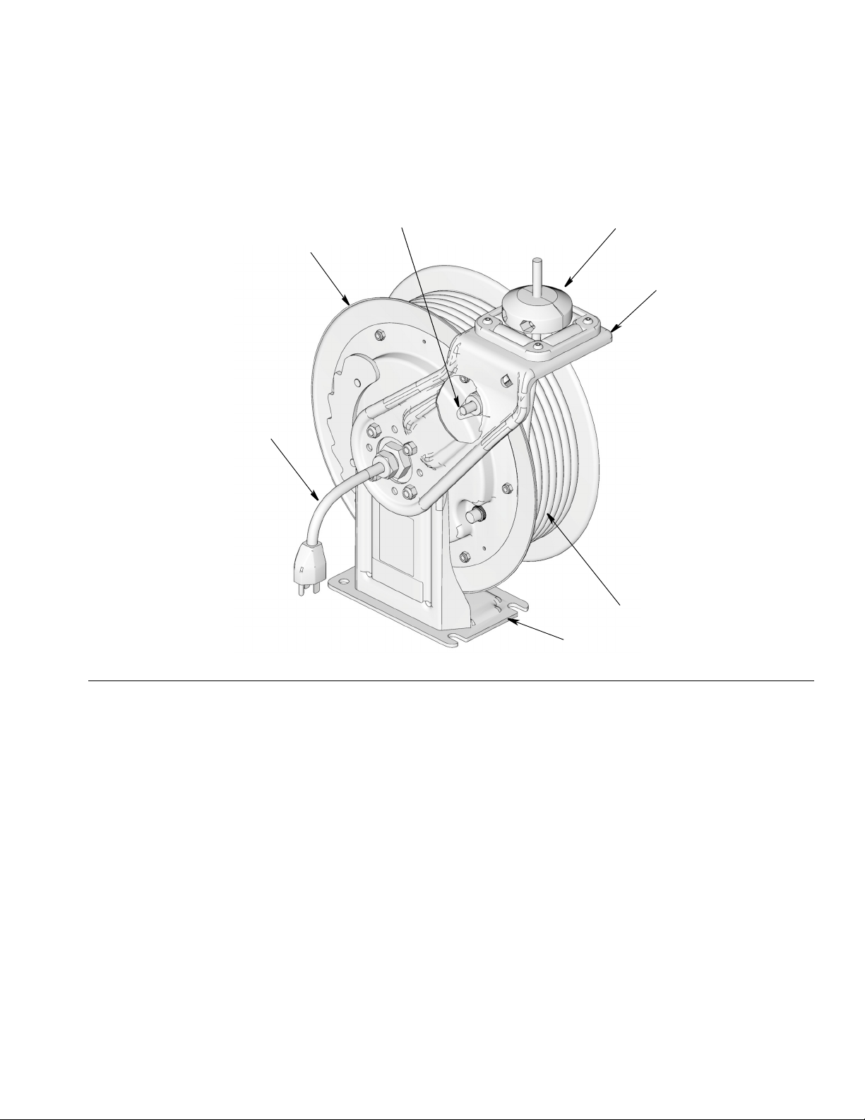
5. Slide cord reel onto the base plate (105) and install
the hold-down plate (104), washer (102) and screw
(101). Tighten the screw firmly (FIG. 5).
The electric cord reel is heavy and may be difficult to
mount without assistance. (See Technical Data, page
26 for weights of cord reel assemblies.) To reduce the
risk for injury:
• Be sure the mounting surface and bolts are
strong enough to support the cord reel’s weight
and stress caused by hard pulls on the accessory
cord.
• When you are mounting a cord reel overhead,
always use a lift truck and be sure it is secure
before lowering the lift truck.
Plate Mounting Kits SD10 SD5
FN Description 24H193 24N686
101 SCREW, 3/8” x 16 x 5/8” 1* 1*
102 WASHER, lock,3/8” 1* 1*
104 PLATE, hold down 1 1
105 BASE, plate 1 1
FIG. 4
FIG. 5
Incorrect
Correct
104 105
102
101
A

Installation
10 3A2592A
6. If needed, adjust spring tension. See the Increasing
Spring Tension or Decreasing Spring Tension sec-
tion of this manual, page 14.
7. Position cord stop at a height that is easily accessi-
ble to the user. Tighten nuts to securely hold stop in
place.
8. Plug power cord into grounded electrical outlet.
Retrofit Bracket
1. Drill holes in mounting surface. Use reel base (103)
as a template for mounting hole position or refer to
FIG. 6 for dimensions.
Dimensions
A 129.5 mm (5.1 in)
B 76.2 mm (3.0 in)
C 101.6 mm (4.0 in)
DØ12.7 mm (0.50 in)
2. Mount reel base (103) to wall or ceiling using 4, user
supplied mounting bolts that are strong enough to
support the weight of the cord reel, cord and acces-
sories. Tighten bolts securely.
3. Mount base plate (105) to reel base (103) using four
screws (101).
4. Continue installation instructions, steps 5 - 8, page
9.
Retrofit Bracket SD10 SD5
FN Description 24N689 24N688
101 SCREW, 3/8” x 16 x 5/8” 5 5
102 WASHER, lock,3/8” 5 5
103 BASE, reel 1 1
104 PLATE, hold down 1 1
105 BASE, plate 1 1
FIG. 6
A
C
B
D
FIG. 7
101
105
104
102
103
101

Installation
3A2592A 11
Ceiling Mounting Without an I-Beam - Open Channel
For SD10 Models order kit: 24A934, 24A935, 24A936, 24A937, 24A938, 24A939
For SD5 Models order kit: 24N674, 24N675
For SD5 Models mounted in an SD10 Model Mounting Channel: SD5 models require a specific hold down plate
designed for SD5 Cord Reels. Contact Graco Customer Service for assistance when ordering these parts.
NOTE: See page 16 for Open Channel dimensions.
1. Ceiling Mount Only: Position cord reel so the reel
base is facing up. Check pawl to make sure it is not
wedged (FIG. 4, 9). (Also see General Installation
Information page 8.)
2. Use the base channel (FIG. 8 - 103) to lay out the
position of the mounting holes before you drill.
3. Drill mounting holes.
4. Install the base channel (103) and base plate (105)
as shown in FIG. 8.
5. Slide cord reel into the reel base (105) and install
the hold down plate (104), washer (102) and screw
(101). Tighten the screw firmly (FIG. 8). Be sure it is
secure before lowering the lift truck.
6. Continue installation following steps 6 - 8 of
Wall/Ceiling Mounting with Plate instructions,
page 9.
Ceiling Mounting Directly to an I-Beam
1. Check pawl to make sure it is not wedged (FIG. 4,
9). (Also see General Installation Information page
8.)
2. Use the mounting template (FIG. 9 - B) to lay out the
position of the mounting holes before you drill
NOTE: Templates to scale are provided starting on
page 28.
3. Drill mounting holes in the I-Beam (C) (FIG. 9).
4. Bolt reel to I-Beam. Be sure it is secure before
lowering the lift truck.
5. Continue installation following steps 6 - 8 of
Wall/Ceiling Mounting with Plate instructions, page
9.
Open Channel Mounting Kits
SD 5 Models SD 10 Models
FN Description
24N674
1 Reels
24N675
2Reels
24A934
1 Reel
24A935
2 Reels
24A936
3 Reels
24A937
4 Reels
24A938
5 Reels
24A939
6 Reels
101 SCREW, 3/8” - 16 x
5/8” 5 10 5 10 15 20 25 30
102 WASHER, lock, 3/8” 5 10 5 10 15 20 25 30
103 BASE, reel, channel 11111111
104PLATE,holddown12123456
105 BASE, plate 12123456
FIG. 8
103
102
101
104
105
FIG. 9
A
B
C

Installation
12 3A2592A
Ceiling Mounting to I-Beam without Drilling
Holes
(Order Mounting Bracket Kit: 204741 for open or
enclosed reels.)
NOTE: For mounting 1-3 reels, two kits are required. For
mounting 4-6 reels, three kits are required.
Mounting Bracket Kit 204741 (SD5 and SD10)
1. Secure mounting brackets (D) to the channel.
2. Position the adjustable clamps (206) of the mount-
ing brackets over the I-Beam (A), and tighten them
securely (FIG. 10).
3. (FIG. 8, page 11): Slide cord reel into the reel base
(105) and install the hold down plate (104), washer
(102) and screw (101). Tighten the screw firmly.
NOTE: For enclosed reels, use the Enclosure Kit Base
Plate (Part No. 302, page 15).
4. For enclosed channel installations, continue with
instructions on page 15. For all other installations,
continue instructions following steps 6 - 8 of
Wall/Ceiling Mounting with Plate instructions, page
9.
Ref Description Qty
201 WASHER, lock, 1/2” 2
202 SCREW, 1/2” - 13 x 1” 2
203 SCREW, 1/2” - 13 x 1-3/4” 2
204 NUT 1/2” - 13 2
205 NUT, spring clamp (not shown) 2
206 CLAMP, beam 2
207 CHANNEL, unistrut 1
FIG. 10
A
D
207
206 203
201 / 202 / 204
205
103
206
D
203
204
201
202
ti13188

Installation
3A2592A 13
Swivel Bracket Mounting Kit
•24N444 for SD10 Models
•24N814 for SD5 Models
Installation instructions are included with the kit.
FIG. 11

Installation
14 3A2592A
Adjusting Spring Tension
Increasing Spring Tension
1. Disconnect cord reel from power source by unplug-
ging power cord from outlet.
2. Pull out accessory cord, 1 to 2 turns and engage
pawl.
3. Pull accessory cord back through cord rollers.
4. Wrap a loop of accessory cord onto the spool.
5. Check the spring tension; the accessory cord must
pull out fully and retract fully. Wrap more loops, one
at a time around the spool until the spring has the
desired tension.
NOTE: Do not put so many loops onto the reel that the
spring winds up tightly before the accessory cord is fully
extended.
Decreasing Spring Tension
1. Disconnect cord reel from power source by unplug-
ging power cord from outlet.
2. Pull out accessory cord, 1 to 2 turns and engage
pawl.
3. Pull accessory cord back through cord rollers.
4. Remove loops of accessory cord to decrease ten-
sion.
5. Check the spring tension. Unwrap more loops, one
at a time from the spool until the spring has the
desired tension.
• Never allow reel to spin freely. Doing so could
cause serious injury if you are hit by the plug,
accessories, or other moving parts.
• Reel must be bolted securely in place when mak-
ing adjustments.

Installation
3A2592A 15
Enclosed Channel Kits
NOTE:
•Foreach SD5 and SD10 Reel : order 1 Enclosed Mounting Channel kit and 1 Side Panel kit.
•Foreach reel bank: order 1 End Panel kit.
• Before installing the Enclosure, adjust the spring’s tension. See Adjusting Spring Tension, page 14.
• SD5 Kits include a mounting bracket (311) to allow the cord reel to be installed to the outlet of the enclosure. If
using an existing SD enclosure with the SD5 Cord Reel, Kit 24P164 is required.
SD5/SD10 End Panel Kit
• 24A950
SD5 and SD10 Side Panel Kits:
• SD5 Metallic Blue - 24N682
• SD5 Red - 24N683
• SD5 Black - 24N684
• SD5 Yellow - 24N685
• SD5 White - 24N690
• SD5 Dark Blue - 24N691
• SD10 Metallic Blue - 24A940
• SD10 Red - 24A941
• SD10 Black - 24A942
• SD10 Yellow - 24A944
• SD10 White - 24A217
• SD10 Dark Blue - 24A943
Enclosed Channel Mounting Kits are available from Graco. Installation instructions are included with the kit. Contact
Graco Customer Service for additional information about ordering these kits.
SD5/SD10 Enclosed Mounting Channel Kit:
• 1 Reel - 203521
• 2 Reels - 203522
• 3 Reels - 203523
• 4 Reels - 203524
• 5 Reels - 203525
• 6 Reels - 203526

Installation
16 3A2592A
GFCI Models: 24M525, 24M526:
Installation In Enclosures
5
Disassembly
Reference letters used in the following instructions refer
to FIG. 12.
1. Disconnect cord reel from power source by unplug-
ging main supply plug from outlet.
2. Loosen four phillips #2 screws (A) on cover (B).
Remove cover.
3. Unscrew two phillips #2 screws (C) to remove GFCI.
4. Unscrew two phillips #2 screws (D) to remove
NEMA receptacle.
5. Disconnect black, white, and green wires from wire
nuts and remove GFCI and NEMA receptacle from
box.
6. Loosen strain relief (E) at the top of the junction box.
7. Remove cord (F) from junction box (G).
Reassembly
1. Route cord through enclosure panel (H) and
through opening in roller guide (J).
2. Insert cord (F) through strain relief (E). Tighten
strain relief with enough service loop wire in the
junction box (G).
3. Connect black wire from cord to black wire from
GFCI module with wire nut.
4. Connect white wire from cord to white wire from
GFCI module with wire nut.
5. Connect green wire from cord to green wire from
GFCI module. NEMA receptacle, and metal junction
box with wire nut.
6. Secure GFCI to left side of junction box using two
phillips screws (C).
7. Secure NEMA duplex receptacle (D) to right side of
junction box using two phillips screws.
8. Reassemble cover (B) with four phillips #2 screws
(A).
9. Test the GFCI with by pressing the test button.
FIG. 12
A
B
CD
E
F
G
H
J

Installation
3A2592A 17
Light Models Installation In
Enclosures
Disassembly
Reference letters used in the following instructions refer
to FIG. 13.
Prior to installing the light (A) in enclosure:
a. Verify cord reel is disconnected from power
source.
b. If not already removed, remove cord stop (17),
roller bracket (13a), rollers and pins assembly
(13a and 13c) from side enclosure (307). See
Repair Manual for this procedure.
c. The hanger bracket assembly (C) on the top of
the light (A) prevents the light from fitting
through the enclosure opening (B) when the
roller bracket (13a) and rollers (13b) are
installed in the opening. To route the light
through the enclosure, these parts must be
removed prior to installation.
1. Insert light assembly (A) through roller bracket
opening (B) located in the top of side panel (307).
2. Remove the roller and pin assembly (13b and 13c)
from the roller bracket (13a). Slide the bracket over
the top of the light and hanger assembly.
3. Snap roller and pin assembly (13 b and 13c) back
into place in the roller bracket (13a).
4. Use 4 screws (13d) to secure roller bracket assem-
bly (13) to enclosure (307).
5. Position the two cord stop (17) halves around cord.
Insert screws (18) through cord stop and hand
tighten nuts (19) to hold cord stop in place. If cord
has a warning tag, cord stop should be installed on
the same end as the warning tag.
6. Pull the cord hard enough to release the latch and
slowly allow the cord to retract.
FIG. 13
13a
13d
13b
13c
17
19 18
307
A
B
C

Mounting Channel Dimensions
18 3A2592A
Mounting Channel Dimensions
(Side dimension for all kits)
1 Reel Base - Used with SD5 Kit 24N674 and SD10 Kits 24A934 / 203521
2 Reel Base - Used with SD5 Kit 24N675 and SD10 Kits 24A935 / 203522
9.0 inch/228.6 mm
7.50 inch/ 190.5 mm
7.75 inch
6.75 inch
0.50 inch/12.7 mm
4 x 3/8-16 UNC-2B
Weld Nut
0.75 inch/19.05 mm
196.8 mm
171.4 mm
7.75 inch/
18.0 inch/457.2 mm
1.5 inch/38.1 mm
7.50 inch/190.5 mm 7.50 inch/
190.5 mm
0.50 inch/
12.7 mm
6.75 inch
171.4 mm 196.8 mm
8 x 39=16 UNC=2B Weld Nut

Mounting Channel Dimensions
3A2592A 19
3 Reel Base Weldment
Used with Kits 24A936, 203523
4-Reel Base Weldment
Used with Kits 24A937, 203524
7.75 in. /
196.8 mm
6.75 in/171.4 mm
7.50 inch/190.5 mm
1.5 inch/38.1 mm
27.00 inch/685.8 mm
0.75 inch/
19.05 mm
0.50 inch/
12.7 mm
12 x 3/8-16 UNC-2B Weld Nut
0.75 inch/
19.05 mm
1.5 inch/38.1 mm
16 x 3/8-16 UNC-2B Weld Nut
6.75 in/
171.4 mm
7.50 inch/190.5 mm
36.00 inch/914.4 mm
0.50 inch/
12.7 mm
7.75 in. /
196.8 mm

Mounting Channel Dimensions
20 3A2592A
5 Reel Base Weldment
Used with Kits 24A938, 203525
6-Reel Base Weldment
Used with Kits 24A939, 203526
7.75 in. /
196.8 mm
6.75 in/
171.4 mm
7.50 inch/190.5 mm
1.5 inch/38.1 mm
45.00 inch/1143 mm
0.75 inch/
19.05 mm
0.50 inch/
12.7 mm
20 x 3/8-16 UNC-2B Weld Nut
7.75 in. /
196.8 mm
0.75 inch/
19.05 mm
1.5 inch/38.1 mm
24 x 3/8-16 UNC-2B Weld Nut
6.75 in/171.4 mm
7.50 inch/190.5 mm
54.00 inch/1372 mm
0.50 inch/
12.7 mm
This manual suits for next models
29
Table of contents
Other Graco Tools manuals

Graco
Graco 350 Series Operation manual

Graco
Graco GX-16 User manual

Graco
Graco SD Series User manual

Graco
Graco 350 Series Operation manual

Graco
Graco XD40 User manual

Graco
Graco MAGNUM C Series Manual

Graco
Graco SD 10 Series User manual

Graco
Graco LD Series User manual

Graco
Graco 24N719 User manual

Graco
Graco SD Series Use and care manual

Graco
Graco 17R720 User manual

Graco
Graco 224268 Operation manual

Graco
Graco 750 Series User manual

Graco
Graco XD40 Setup guide

Graco
Graco 200 Series Operation manual

Graco
Graco LD Series User manual

Graco
Graco 309446A Parts list manual

Graco
Graco Twistork 224854 Parts list manual

Graco
Graco SD Series User manual

Graco
Graco 223688 Operation manual