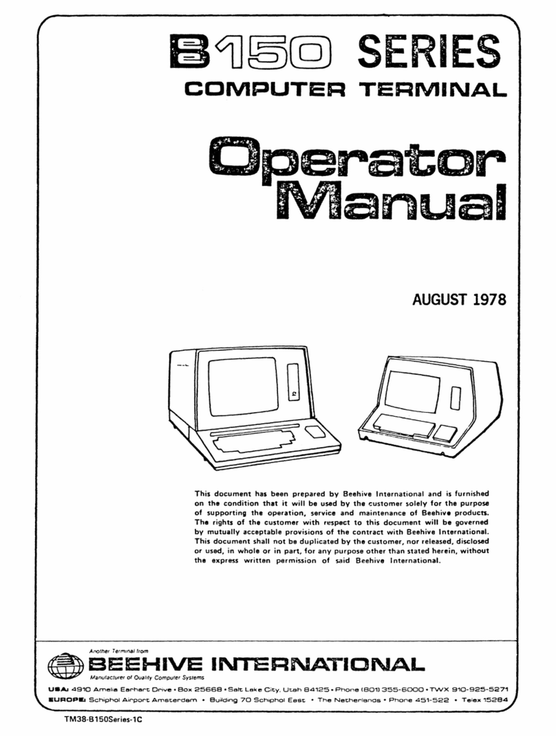
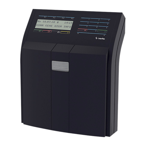
Beehive International B102 User manual

BlOO
Series
Terminals
BlOO,
B102, B150,
8152,
B160, B162
^
L»i=
Manual
JULY
1978
Thij document has been
prepared
by
Beehive
International and is
furnished
on the condition that it will be used by the customer solely for the purpose
of
supporting
the
operation,
service
and
maintenance
of
Beehive
products.
The
rights
of the
customer
with
respect
to
this
document
will
be
governed
by
mutually
acceptable
provisions
of the
contract
with
Beehive
International.
This
document
shalt
not be
duplicated
bythe
customer,
nor
released,
disclosed
or
used,
in
whole
or in
part,
for
any
purpose
other
than
stated
herein,
without
the expresswritten
permission
of said
Beehive
International.
BEEHIVE
INTER
NATIONAL
«=lr^
=>^fiKS.SniLLBke
C.lvUc.eMa'3125-P'^or-e
IB01)
355
SOOO
•
Twx
9XD
925 5271
UUAi
d
910
Amefca E»r^^^rL
0«^vc
'Bo*
2&6SB
Soil,
Lone
uav.
uten
o ^
—.-oo
.
l/uBOP«.
Scrvpr^oi
A,r-oort
•
D.W-O
7Q
Ee«t
•
Tn«
rv;etne.,ana»
•
Pnone
030->S15a2
1^.
152B
JluF*o«Hil?cJsia
Mesa
540
e.i04
rm
9-0.595-2572
.
Sunnyvale
1^08]
739--560
FLOBJDA
A,«mon.e
Sp^i^
SJoimA
SWM5U45
ILLINOIS
Elk
Grove
Village
(2t2,
S93-1565
MASSACHUteTTS
^"9>on
^6
WFW
VOHK
N9*
YorK
/2I2;
6e?-2760
OHIO
Cinc.nnati
(5t3l
621-8277
PENNSYLVANIA
Plymoulh
Meeang
TEXAS
Dallas
f2''J/3fl7.1856
UTAH
SaB
Lake
Cily
WO
355-6000
TWX
9'0-925-527i
VIBQINIA
Falls
Chufch
C703;
356-5
33
i
TM76-B100-2B/TM38-B150-2B

TABLE
OF
CONTENTS
SECTION
TITLE
PAGE
SECTION
IV -
THEORY
OF
OPERATION
4.1
INTRODUCTION
4-1
4.2
GENERAL
FUNCTIONAL
OVERVIEW.
4-1
4.2.1 Power Supply 4-1
4.2.2
CRT
4-1
4.2.3 Keyboard 4-5
4.2.4 Logic Board 4-5
4.3
OPERATIONAL
FLOW
DIAGRAMS
4-8
SECTION
V -
TROUBLESHOOTING
5.1
INTRODUCTION
5-1
5.2
PREVENTIVE
MAINTENANCE
5-1
5.2.1 Troubleshooting Equipment 5-1
5.3
CORRECTIVE
MAINTENANCE
5-1
5.3.1 Troubleshooting Preliminary Considerations 5-2
5.3.2 Troubleshooting Flow Diagrams . 5-2
5.3.3 Full-Duplex Echoplex Test 5-2
SECTION
VI
-
DRAWINGS
&
SCHEMATICS
APPENDIX
A -
MONITOR
Section
1 -
GENERAL
INFORMATION
1.1
MONITOR
DESCRIPTION
A-1
Section
2 -
THEORY
OF
OPERATION
2.1
VIDEO
AMPLIFIER
A-1
2.2
VERTICAL
DEFLECTION
A-2
2.3
HORIZONTAL
DEFLECTION
...........
A-4
Section
3 -
PRELIMINARY
ADJUSTMENTS
3.1
Synchronization
and
Drive Signals A-6
3.2 Brightness A-6
3.3
Video
Contrast
A-6
3.4 Vertical Adjustments A-7
3.5 Horizontal Adjustments A-7
3.6 Focus Adjustment A-8
3.7 Centering A-8
Section
4 -
TROUBLESHOOTING
and
MAINTENANCE
4.1 Troubleshooting Guide A-9
iii

TABLE OF CONTENTS (concluded)
APPENDIX
B -
GLOSSARY
APPENDIX
C -
PROGRAMMABLE
LOGIC
ARRAY
Programmable LogicArray Inputs
Operation
Code
Assignment.
. C5
ff
Program Listing
TABLE
5-1
FIGURE
4-1
4-2
LIST
OF
TABLES
DESCRIPTION
PAGE
Troubleshooting
Flow
Diagram
Index
5-3
ff
LIST
OF
ILLUSTRATIONS
DESCRIPTION PAGE
Basic
Block
Diagram
-
B100/B102
^*2
Basic
Block
Diagram
-
B150/B152
4*3
4-3
Power
Supply
Block Diagram
4-4
Character
Dot
Matrix
4-5 Character
Dot
Matrix of B150/B152
4-6
Timing
Diagrams
4-7
Basic
Functional
Flow
Diagram
4-9
4-8
Basic
Functional
Flow
Diagram
^•'•0
5-1
Echoplex
Test
Connector
^*2
6-1 B100/B102 Logic Board . • . :
B100/B102
Logic
Board
Schematic b-^ tt
6-2
B150/B152/B160/B162
Logic
Board.
6-18
B150/B152/B160/B162
Logic
Board Schematic
b-19
t-i-
6-3
B100/B150/B160
Case
Removal
6-35
6-4
B100/B150/B160
Disassembly
6-36
6-5
B102/B152/B162
Disassembly
6-37
6-6 Keyboard Disassembly * * '
6-7
B100/B150/B160
Cable
Assembly
Drawing/Schematic.
. .
6-39
6-8
B102/B152/B162
Cable
Assembly
Drawing/Schematic
. . . 640
6-9
B100
Series
Keyboard
Assembly
112-1326
641
6-10
B100
Series
Keyboard
Assembly
112-1775
G-42
6-11
Keyboard
Schematic
112-1326
643
6-12
Keyboard
Schematic
112-1775
644
1
Voltage
Waveform
2
Interconnecting
Cabling
Diagram
A-11
3
Circuit
Board
Components
Location
A-11
4
TV5,
9
and
12
Without
Power
Supply
A-12
IV

SECTION
IV
Theory
of
Operation
4.1
INTRODUCTION
bly. The
DC
regulators used in
the
B100 Series
terminals
are
overcurrent
and
thermally
protected.
The
TOC
type
regulator is a 10 amp in
the
B100/
B102
and
a 2
amp
in
the
B150/B152
and
is
mounted
to
the
chassis via a large finned sink.
The
regulator
subassembly is
connected
to
the
Logic Board
through a cable assembly (see Figure
-3).
For
identification
and
specific
regulator
replacement,
consult
the
B100
Series
Illustrated
Parts
Breakdown
under Section III, "Major Assembly Components."
RECTIFIER
RECTIFIER
TRANSFORMER
♦5
REGULATOR
IS
REGULATOR
ISvOC
This
section
of
the
Service
Manual
contains
the
Theory
of
Operation
for
th6
B100
Series terminals.
This discussion is
presented
as a
functional
descrip
tion
at
a
detailed
block
diagram
level
referencing
appropriate
functional
blocks
on
the
diagram.
This
manual is
intended
to
help
the
customer
service
the
terminal
to
a
subassembly
level.
Individual
compo
nent
replacement
Is
not
discussed
in
detail
and
the
customer
is
advised
to
send
subassemblies
to
a
quali
fied Beehive repair area
for
service, if required.
It
should
be
noted
that
all BlOO
Series
terminals
operate similarly and are essentially identical. Where
there
are
critical
differences,
however,
the
manual
will
indicate
these
with
separate
explanations.
4.2
GENERAL
FUNCTIONAL
OVERVIEW
The
B10G
Series
consists
of
four
basic
functional
components:
the
main Logic Board (with Power
Supply),
the
keyboard,
the
CRTwith electronics,
and
small
separately
mounted
chassis
components
(i.e.,
fan, switches, filter, and regulator/transformer).
Figure
4-1
shows
the
basic functional block diagram
of
the
terminal.
These
functions
are
briefly
described
in following paragraphs.
Note
that
there
are
two
two
different
versions
of
the
block
diagram: Figure
4-1
describes
the
B100/B102
and
Figure
4-2
de
scribes
the
B150/B152.
4.2.1
PowQr
Supply
The
Power
Supply
provides
the
required, regulated
DCvoltages
to
the
terminal.
This
assembly
will
operate
on 100, 115
or
230
VAC
power
50/60
Hz.
Section
II
of
the
Operator
Manual
contains
Power
Supply
voltage
change
information.
The
Power
Supply
provides +5, +15, +12,
—12
VDC
to
the
circuitry
from
a
standard
AC
sourca
Figure
4-3 is a
block
diagram
of
the
Power
Supply
subassem
^
15/230
vACINPUT^
BLOCK
12
REGULATOR
4-1
RECTIFIER
-12
REGULATOR
l2vOC
-l2vOC
Figure4-3 Power Supply Block Diagram
The
power
applied
to
the
Power
Supply
is stepped
down in voltage.
The
transformer
output
voltages
are
rectified
by
three
bridge
circuits.
The
output
from
the
rectifiers
and
filters
provides
power
to
the
+5, +15, +12
and
—12
VDC
regulator
circuits
These
components
are located on
the
Logic Board.
The
main
transformer
is
chassis
mounted
and
con
nected
to
the
Logic Board
through
acable assembly
(see
Parts
Manual
Section
III).
4.Z2
CRT
The
Monitor Assembly includes a 12 inch (30.5cm),
diagonally measured, CRT
and
its
supporting
solid-
state
circuitry.
The
nronitor is
controlled
by
the

n
c
S
CO
_*
o
o
OT
O
ro
PLA
INPUT
SELECTION
MODE
PROGRAMMABLE
LOGIC
ARRAY
COMMAND
DECODEB
» s a
2«(58S
3 *n « o
MAIN
PORT
AUX
PORT
DATA
op
2

(O
MAIN
PORT
CONFIC.
SELECTION
AUX
PORT
CONFIC
SELECTION
PORT
SELECTION
CIRCUIT
RECEIVER
DATA
INPUT
BUFFER
OPERATION
INS
MODE
format
BUSY
f
MODE
CRVSTAL
OSCULATOR
DATA
UART
TRANSMITTER
MODE
BUSY
DATA
READY
DOT
POSITION
7
DPC
BAUD
CLOCK
SELECTION
ROTARY
CHAR
POSITION
^
96
CPC
CHC
HAUD
CLOCK
CKT.
MAIN
t;LK
AUX
CLK
i
SET/C
CHAR
HLICHT
-10
CHC
CURSOR
POS
CURSOR
LINE
ROLL
WRITE
BUNK
SgTTgp
WRITE
PR01.
CURSOR
POS
eUftjt6R
LINE
SEQUENCE
COUNTER
SEQUENCE
VIDEO
CURSOR
GENERATION
CIRCUIT
CURL
CURSOR
UNE
REG.
BCURL
BUFFERED
CURSOR
LINE
OPERATION
REGISTER
CURSOR
UNE
roll
counter
OPERATION
CHAR
UNE
27
CLC
MEMORY
ADDRESS
MANIPULATION
192(9 X 1
BIT
BLINK
UI.INK
SYNC
CEN.
DRIVE
GEN.
BUNXAOW
CIRCUIT
COMPOSITE
VIDEO
DRIVER
V
DRIVE
H
DRIVE
VIDEO
VIDEO
DRIVER
j CURSOR
VIDEO
SHIFT
REGISTER
TO
REMOTE
_
MONITOR
TO
MONITOR
1921J X I
BIT
PROTECT
PR0fB6t
X 7
BITS
data
REFRESH
MEMORY
CURP
CURSOR
POSITION
REG.
CURSOR
POSITION
BCURP
BUFFERED
CURSOR
POSITION
Roa
VIDEO
CURSOR
"OFF
SCREEN
CIRCUIT
CHARACTER
GENERATOR
UJWER
UPPER
^ CHC \
CASE
CASE
INSEBT/DELBTE
CIRCUIT
1
KEYBOARD
CONTROL
LOGIC
FROM
keyboard
Figure
4-2
Basic Block Diagram —
B150/B152

vertical and horizontal synchronization signals
and the video signals generated on the Logic Board
A
fj^l
screen
of
information
consists
of 24
lines
of
80 characters.
The
dot
pattern
for
character
heights
varies
between
B100/B102
and
B150/B152.
The
B100/B102
has
a 9
dot
character
height
with
a
two-raster scan between characters
and
the
B150/
B152 has a
10-dot
character
height
with
one
raster
scan
between
lines
if
lower
case
characters
are
used (see Figures
44
and 4-5).
Brightness
and contrast adjustmentsare provided
by external potentiometers located on
the
rear
panel
(see
Section
II
of the Operator
Manual).
Other monitor adjustments are discussed in Ap
pendix
A.
OOT 0
lUM
ottrtn
eoT
«
eoT
0
•LAM
eMtRiCTM
OltrLAT
eoT
•
tLAM
ano o ooooooooo
"o
•o o o•oo•• • ••o
o•ooo•oo•oooo0
o•ooo•oo•ooooo
CMARACrCII
.
ttlPkAT
o• • •••oo••••oo
o•ooo•oo•o0ooo
o•ooo•oo•ooooo
•ooo•oo•oooo o
oanooo o 0ooooo
1
r\
•AAo o o ooooo
ww
rOMClMOII
oooo o oooooooo
o•••••o o •o
o.
o•o
o•Oooooo•ooo•o
o•oo o ooo•ooo•o
eiUJIACTCII^
o• • ••ooo•••• • o
o• o ooooo•ooo•o
o•ooooo o •ooo•o
^o •oooooo•ooo•o
1
r\
("k o
rj
oo o ooooooo
•*o
oooooo o oooooo
roneuMOM
Figure
4-4
Character
Dot
Matrix
of
B100/B102
4-4
The monitordisplaysdata on the
CRT
in a pattern
determined
bythe
vertical
and
horizontal
synchro
nization
signals
and
the
video
information
driving
signals.
A
+15
DC
voltage
is
applied
bythe
Power
Supply
to
the
monitor.
Vertical Synchronization is applied to the vertical
oscillatorand triggers it at the vertical
refresh
rate
determined by the
driving
logic.
The
vertical
fre
quency isstablized by the vertical frequencycon
trol,
which
determines the point of oscillation. The
output
pulse
of the
vertical
oscillator
is
applied
to
the
driver
amplifier
which
shapes
the pulseand is
controlled by the vertical linearitycontrol. The
output of the
driver
amplifier is
applied
to the
vertical driver by way of the height control. The
eiuiuett*^
mruT
'
•O
'o
O
O
O
O •
O •
-O •
•o
o
o o
•o
o
o •
o •
o •
o •
o •
o •
o •
•o
o
o o
BOt
«
»ST
0
name
1.
o o
o o
o o
o •
o •
o o
o o
o •
o o
eiuiiieii*
>
o o o
tOT
«
fLUM
Figure 4-5 Character Dot Matrix
of
B150/B152

vertical driver
output
pulse is applied
to
the
yoke
of
the
CRT
and
causes
vertical
deflection.
The
re
fresh
rate
is
50-60
Hz
switch
selectable.
Horizontal
Synchronization
pulses
are
applied
to
the
horizontal amplifier where
they
are amplified
and applied
to
the
horizontal driver.
The
output
of
the
horizontal drive is applied
through
the
width
coil
to
the
yoke, where it causes
the
horizontal de
flection.
The
horizontal
deflection
signal
Ts
stepped
up to approximately 12 kvwhere it is then recti
fied, filtered and applied
to
the anode cap of
the
CRT
to
provide
the
high voltage required.
Video
Information
is applied
to
the
video ampli
fier by way of
the
contrast
control, external
to
the
monitor.
The
video
information
signal
from
the video amplifier is applied
to
the
cathode
of
the
CRT gun
to
cause an ON/OFF
condition
cor
responding
to
light patterns of
the
screen. The
brightness control is external to
the
monitor
and
varies
the
voltage on
the
accelerating grid of
the
CRT.
4.2.3
Keyboard
The Keyboard is
the
input device used by
the
operator to communicate with the terminal. The
Keyboard contains
the
switches and supporting
circuitry to generate
the
appropriate control sig
nals
and
ASCII
codes
utilized
in
the
B100
Series
terminals.
The
Keyboard
conforms
to
the
pro
posed
ANSI
keyboard standard for data keys,
but
has been expanded to facilitate the capabilities
of
the
B100
Series
terminals.
The
ASCII
code
chart
is
found
in
Section
III
of
the
Operator
Manual.
The Keyboard enables
the
operator
to
manually
input information to
the
terminal. When a key
is depressed,
the
keyboard logic generates
the
corresponding 7-bit
ASCII
code and presents the
data in parallel form
to
the
keyboard data lines.
After a short delay for debouncing,
the
strobe is
driven
to
its
active
level
and
returns
after
approxi
mately 30 milliseconds. For those keys which auto-
repeat, the strobe line is pulsed at a 15 character
per second rate. The
BREAK
key is
not
encoded
but
is a
function
line
that
is driven
low
for
approxi^
mately
400
ms when
the
key is depressed. The
following keyscause special 8-bit
(non-ASCII)
4-5
codes:
AUXSEND,
CLEAR/HOM^
SEND,
EOS^
EOL,
and
DELETE
CHAR.
Thesecodes are
used
internal
to
the
CRT
only
and
are
not
trans
mitted.
424
Logic
Board
The
Logic
Board
containsthe majorfunction and
control circuits in
the
B100 Series terminal. It also
holds all of
the
DC
voltage regulators
to
power the
unit
with exception of the +5V regulator. The
basic
operations accomplished by the main
logic
board are: Generation of
data
and control signals
for
the
monitor, interaction with
the
keyboard,
control
of
the
data
sent
between
the
BlOO
terminals and any external device, and generation
of the basic timing signals essential for the oper
ation of
the
terminal. (See Figure 4-6)
Display Organization - B100/B102 —The main
timing chain (oscillator,
dot
position counter,
character position counter, character height
counter, and character linecounter) defines the
configuration of the display on the
CRT.
There
are 30
lines,
six of which are used for vertical
retrace and 24 of which are used
to
display
char
acters.
The
30
lines
are
composed
of
nine
scans
each,each scan being composed of 96 character
positions,
80 for
display
and
16
for
horizontal
re-
traca
Each character block is composed of 7 x 9
dot
matrix
field which
contains
a
5x
7
character
matrixfor the displayed character
(see
Figure44).
DisplayOrganization -
B150/B152
—The main
timing
chain
(oscillator,
dot
position
counter,
char
acter position counter, character height counter,
and character line counter) defines the configuratior
ofthe
display
on the
CRT.
There
are27
lines,
three
of which are used for vertical retrace and 24 of
which are used to display characters. The 27 lines
arecomposed of ten
scans
each, eachscan
being
composed
of 7x 10dot
matrix
field
which
contains
a 5 X7 character matrix for the displayed char
acter (see Figure 4-5).
Oscillator - The oscillator is crystal controlled
with a frequency of
10.8864
MHz.
Two
74H04'!
are connected in series by a lOOpfcapacitor.

osc
jTjuimfmiiruinmiirinjiruin
Bpci
j-unjT__rTJTJ~i_rLrLri
—i_i—u—i—j—u—I
I—1
__i
1 I 1 I 1
DPC8
U
FREQ
-
10.8864
MHz
DOT
POSITION
COUNTER
FREQ
-
1.5552
MHz
CHARACTER
POSITION
COUNTER
CPC1
CPC2
CPC4
_
CPC8
_
CPC16.
CPC32^
CPC64_
CPC80
juinnnjTJinnnnjiriAnnjiruuinjifuuifiiinJUinAnjinruiriJinjiJiAAJiri^
j—I
m
rn
r
CHC1
n__rn
m—r~L
CHC2
CHC4
CHC8
CLC1
J—i_rn
i_f
CLC16
CLC2
CLC4
CLC16
Figure 4-6 Timing Diagrams
4-6
i_r-i_rn_r
CHARACTER
HEIGHT
COUNTER
FREQ.
°
1.800
KHz
CHARACTER
LINE
COUNTER
(50
Hz
OPERATION)
FREQ
"SO
Hz
CHARACTER
LINE
COUNTER
(60
Hz
OPERATION)

Each
74H04
has
a 1
kohm
feedback
resistor
around
it. A
10.8864
iVIHz
crystal is
connected
from
the
input
of
the
first
74H04
to
the
output
of
the
second. The
output
of
the
oscillator
is
buffered,
inverted
and
fed
to
the
Dot
Position
Counter.
Dot
Position
Counter
-
This
divide-by-seven
counter
defines
each
of
the
seven
dots
required
to
compose
one
character.
The
outputs
of
this
four-stage
counter
are labeled DPCl,
DPC2.
DPC4
and
DPC8.
The
counter
actually
presets
to
a
count
of
10,
counts
up
through
the
overflow
point
at 15
to
a
count
of
zero,
and
presets
back
to
a
count
of
10.
The
Dot
Position
Counter
output
DPC8 drives
the
Character
Position
Counter.
Character
t'\»sctcon
Counter
-
The
Character
Position
Counter
is
composed
of
two
binary
type
counters
that
define
96
character
posi
tions,
each
being
seven
dots
wida
The
output
of
the
Character
Position
Counter
drives
the
Character
Height
Counter.
Character
Height
Counter
-
The
Character
Height
Counter
is a
standard
counter
that
de
fines
nine
scans
of
96
characters
each,
with
each
character
being
seven
dots
wide.
The
output
of
the
Character
Height
Counter
drives
the
Character
Line
Counter.
Character
Line
Counter
-
The
Character
Line
Counter
is a
binary
counter
that
starts
at
a
count
of
zero
and
counts
to
a
maximum
of
29
for
a
total
of
30
character
lines.
The
final
out
put
of
this
counter
runs
at
the
vertical refresh
rate.
Horizontal
and
Vertical
Drive
-
The
Horizontal
Drive
is
started
when
the
Character
Position
Coun
ter
leaves
the
video
area
of
the
scan
and
is
active
for
the
following
40
character
positions.
The
high active
ouiput
of
this
flip-flop is
sent
to
the
monitor
on
pin
9
of
connector
J1.
The
Vertical Or've is
generated
during
the
time
the
Character
Line
Counter
is
decoding
24.
Cursor
Location
Counter
identifies
the
location
of
the
cursor.
This
is a
count
made
from
the
Cur
sor
Line
Counter
(called
CURL)
and
the
Cursor
Position
Counter
(called CURP).
These
two
coun
ters, in conjunction with
the
ROLL
counter, are
ised
to
address
the
memory
to
determine
the
entry
joint
of
the
next
character.
The
cursor
location
4-7
counters
are
compared
with
the
next
character.
The
cursor
location
counters
are
compared
with
the
Character
Position
Counter
and
the
Character
Line
Counter
to
generate
the
signal
called
CNTR
CURSOR.
This
signal is used
to
generate
the
cursor
displayed on
the
CRT.
Also associated
with
the
cursor
location
counters
is
the
appropriate
circuitry
to
move
the
cursor
up,
down,
right, left;
home,
etc
A
LINE
FEED
code
causes
the
Cursor
Line
Counter
to
increment
by
one. A CARRIAGE RETURN
code
clears
the
Cursor
Position
Counter.
With
the
terminal
operating
in
Format
Mode,
when
the
cursor
is
incremented
off
the
bottom
line,
the
cursor
automatically
wraps
around
to
the
top
of
the
display,
i.e.,
the
Cursor
Line
Counter
is
reset
to
zero.
However,
if
the
terminal
is
not
in
Format
Mode,
the
display
scrolls
whenever
the
cursor
incre
ments
from
a
count
of
23.
A
scroll
is
initiated
by
any
of
three
functions
if
activated
when
the
cursor
is
on
the
last
line
of
the
display
and
the
terminal
is
not
in
Format
Mode:
a.
LINE
FEED
or
CTRL
J
b.
CURSOR
DOWN
or
ESC
B
c. If
the
cursor
is
on
the
last
position
of
the
last
line
1.
Cursor
right
2.
Any
displayable
character
3.
Space
Memory
is
actually
a
2048
byte
memory.
Each
byte
consists
of
9
bits:
7
for
data,
one
for
protect,
and
one
for
blink. Of
these
2048
bytes,
1920
are
displayabl&
The
program
does
not
have
the
capa
bility
of
displaying
or
writing
into
the
remaining
128. In
order
to
write
data
into
the
page
memory
from
the
receiver,
the
memory
address
is
muxed
over
to
the
cursor
location
registers
and
the
sig
nal WRITE is
generated.
The
UART is
then
reset
and
is
capable
of
receiving
the
next
character.
The
page
memory
output
is
sent
to
the
character
gene
rator
input
buffer
at
the
proper
time
to
generate
the
displayable
characters.
The
program
has
the
capability
of
shutting
down
the
screen
refresh
for
any
given
operation
to
increase
the
program
operating
time.
Character
Generator
is a
read-only
memory
(ROM)
that
is
addressed
by
the
character
(in
ASCII).
The
scan
configuration
and
the
chracter
indicate
the
pattern
desired
on
that
scan. Five-bit
dot
pat
terns
are
generated
which
form
a
portion
of
a

character.
The
output
of
the
character
generator
is
applied
to the
parallel-to-serial
video
shift
regis
ter.
Video Shift Register is parallel-to-serial loaded
with data by the low-active
signal
DPC8
and is
clocked by the
main
oscillatoroutput. The dots
are shifted out, mixed with cursor information
and blanking
signals
and appliedto the monitor
through the
CXDNTRAST
control as
video
infor
mation.
Input/Output Operations
UART
(Receiver) data
can be received by the
B100
Series terminals from
one of
three
sources: from
the
two
I/O interfaces
into
the
receive side
of
the
UART
or
from
the
keyboard through the transmit sideof the
UART
to
the
receive
side
of
the
UART.
The UART is driven by a clock generated
inter
nally off the main counter chain. No separate
oscillator is required. A rotary switch located on
the back panel switches the clock rate for oper
ation from 75
to
19200
baud
The
times-16 clock
isthen applied to the transmitter and
receiver
of
the
UART.
The
EIA line receiver receives
data
at
RS232C
levels
and
gates
them into the
UART
when on
line.
Through
the
same
gating,
data isbroughtin
from
the
transmit
side
of
the
UART,
where
it is
con
verted to parallel (7 bits) data.
UART
(Transmit) keyboard data linesfor bits 1
through 7 areapplied to the transmit input data
lines
along
with the
seven
BUS
lines.
Also
coming
from the keyboard circuit isa load
signal
which
triggers
the
UART
to initiatethe
transmission.
As
the
UART receives
the
character
for
transmission,
it performsthe appropriate parity generation, pro
vides one or two stop bits, divides the X16 clock
to get the baud rate,and transmitsthe character.
The character isapplied through an
EIA
RS232C
interface
to
the
computer
or
modem.
Alsocoming from the
UART
is output data at a
TTL
level
which is applied to the receiver side of
the
UART
through the previously mentioned logic
The
EIA
interface
includes aData
Terminal
Ready
signal
which
indicates
the status ofthe unit to the
computer anda
Request
to
Send
signal
which
in
dicates
that
the
terminal has
data
to
send
to
the
computer. The
Clear
to Send
line
coming
from
the
computer ismonitored at the
EIA
RS232C
inter
4-8
face
levels.
It is received by a line receiver which
converts it to
TTL
levels
and appliesit to the
UART
clock control circuit to control transmission. An
optional
X8
clock
(TTL
levels)
is
available
aspart
of
the
interface.
The
BREAK
key is
on
the
key
board and enables a timer which holds the transmit
data
line
in
a
spacing
condition
fora
predetermined
length
of
time.
Block
Send
Circuit
allows
the
operator
to
compose
a
message
on the terminal
screen
andthen,
depress
ing
the
SEND
key,
cause
the
terminal
to
send
the
entire
message
to the computerat the
selected
baud
rate. Thesequence of operations isdescribed in
Figure
4-8.
The
operation
is as follows:
1.
2.
3.
4.
5.
6.
7.
Raise Request-to-Send
When Clear
to
Send,
send STX (002)
header
Send
data
If FORMAT
and
END OF PROTECTED FIELD,
send
HT
code (III3)
If
not
FORMAT
and
ENDOF
LINE,
send
CR/LF
sequence
(0159/0123)
When
end of
message,
sent
ETX
(OO33)
Time
out
and
drop
Request
to
Send
Auxiliary Send Circuit is identical
to
the
Block
Send except for two points:
1. The
message
istransmitted out the
AUX
port insteadof the
Main
I/O
port
2.
The
delimiters
sent
at
the
start
of
message,
end of unprotected field, end of line, and
ETX
are
selected
from
a
different
portion
of
the
Block
Send
ROM
Special Function
(F1-F16)
sends a code sequence to
the computer from the terminal. The code is
insti
gatedby
pressinggany
one of the 16function
keys.
1. An
STX
istransmitted
(0223)
2.
An
Escape
code
(O333)
3. Code character
(see
/\SCII
Code Chart, Table
3-2)
4. Andends with an
ETX
(OO33)
4.3
OPERATIONAL FLOW DIAGRAMS
See Figures 4-7 and
4-9.
These diagrams
give
the
user an
outline
of
the
B100/B150 terminal
operation. Specific program information is con
tained in Appendix C and a list of programmable
I.
C.
part numbers and program numbers is con
tained
in
the
Parts
Breakdown
Manual.

fx
(b
^escwait)
UU.
IN
UFFE
SAVE
CUBSOR
LOCATION
SEND
CURSOR
TO
UNE
23
REFRESH
DISABLE
SAVE
CURSOR
LOCATKMJ
WRITE
NULL
TO
MEM.
INCaCUR.
POSITION
URSOR
LLEGAL
clear
cur
POSITION
INCR
CUR
UNE
URSO
ILLEGAL
CLEAR
CURSOR
UNE
DECR.CUR
UNE
GO
TO
"BPT"
GO TO
"RTN
CURSOR"
GO
TO
"LF"
NULL
CODE
TO
REG
2
CLEAR
STORED
CURSOR
UNE
PROTECTED>V-
WRITE
NULL
TO
MEM.
INCaCUR.
POSITION
CURSOR
CLEAR
CURSOR
POSITION
CO
TO
"ADV
HOME
CURSOR
SAVE
CUR
LOCATIC»(
GO
TO
"FPr
GO
TO
"RTU
CURSOR
CO
TO
"BKSP
NULL
CODE
TO
REG
2
REG
2
BUS
DISABLE
CLEAR
CUR
POS.
!•
UNE
HOME
CURSOR
FMT
"OFF*
CLEAR
WRITE
PRCT
FLOP
SET
WRITE
PROT.
FLOP
ENABLE
KEYBO.
DISABLE
KEVBa
CO
TO
"FPT"
UTERAL
BUS
FIRE
TIMER
TIME
SEND
1st
BYTE
-SOM-
SEND
2nd
BYTE
-SOM-
CLR
CUR.
POSITION
DECa
STORED
CUR.
UNE
MEMCmY
BUS
DECa
STORED
CURSOR
INCaCUR
POSITION
Figure
4-7
Basic
Functional
Flow
Diagram
SETWRITE
UNK
FLO
CURSOR
ILLEGAL
INCaCUR.
POSITION
CURSO
ILLEGA
URSO
LEAR
W
UNK
FLO
UTERAL
BUS
SEND
lat
BYTE
END
UNPRQ]
SEND
2nd
BYTE
END
UNPRCI
SAVE
CURSOR
CLEAR
CUR.
UNE
ENABLE
AUX.
XMIT.
GO
TO
-FPT-
URSO
SEND
Ist
BYTE
-EOL-
SEND
2nd
BYTE
-EOL-
dECR
STORED
CUa
UNE
CLR.CUR.
POSITION
INCUCUR
UNE
SEND
ist
BYTEEOM
SEND
2nd
BYTE
EOM
I
FIRE
TIM
GO
TO
"IDLE-
SAVE
CURSOR
CLEAR
STORED
CURSOR
UNE
LOVEK
CASE
SAVE
BYTE
UNDER
CURSORl
WRITE
LC
CODE
TO
MEM
LCCODE—•RZ
SAVED
BYTE
TO
MEMORY
FIRE
TIMER
TIME
SEND
Ist
BYTE
-
STX
-
SEND
2nd
BYTE
-
ESC-
SEND
IC
CODE
FROM
R2
ND
3rd
BYTE
-
ETX
-
i
I FIRE
HM^
TIME

o
ULL
I
BUFFER
DEL.
IN
buffer
INCR
CUR
POSITION
ILLEGAL
CLEAR
CURSOR
l>OSlTION
GOTO*lF
lUXGAL
TO
TO'BIt'
CR
CODE
CLEAR
CURSOR
POS.
GO
TO'FPT
HOME
CURSOR
GO
TO
IDU
^N
CURSO^
DECR
STORED
UNE
COUNT
DECR
STORED
POS.
COUNT
ILLEGAL
INCR
CUR.
posmoN
ILLEGAL
LEAR
CURSOR
POSITION
INCR.
CUR.
UNE
DECR.
SrCMED
UNE
COUNT
DECR
STORED
POS.
COUNT
LF
CODE
INCR.CUR.
UNE
CURSOR
LLEGAL
FMT
MODE
SAVE
CURSOR
posmoN
ERASE
BOTTOM
LINE
CURSOR
TO
FIRST
POS.
LASTUNE
GO
TO
RTN
CURSOR
GO
TOTPT
BKSP
CODE
DECR
CUR.
POS.
GO
TOW
URSOR
ILLEGAL
CURSOR
TO
POS.
79
CO
TO'UP
GOTO
•idle*
GO TO'BKSP *
Qpowmoj^
HARDWARE
CLEAR;
i:uR.posiriOM
CUR
UNE
WRITE
PROT
GOTO*EOS
FIRE
BEEPER
GO
TO*FPr*
INCR
CUR.
POSmON
ILLEGAL
CLEAR
CUR
POSITION
IMCR.
CUR.
UNE
ILLEGAL
•home*
CURSOR
GOTO
CODE
SAVE
CURSOR
CLEAR
CURSOR
GO
TO
•start
send*
GO
TO'ADV.*
Figure
4-8
Basic
Functional
Flow
Diagram
C1£AR
INPUT
BUFFER
SETSEQS
GOTO
ESC.VAIT*
!V
CTRU
CODE
INSERT
MODE
SAVE
BYTE
UNDER
CUR.
IN
REG
1
WRITE
NEW
CODE
UNDER
CURSOR
REFRESH
OfF
SAVE
CUR.
POSmON
INCR
CUR.
POSmON
ILLEGAL
RE&2
MEMOBY
WRITE
NEW
BYTE
UNDER
CURSOR
I
GOTO^DV.
CLEAR
CURSOR
POSmON
INCR.
CUR.
GOTO
•rtn
cursor'

SECTION
V
Troubleshooting
5.1
INTRODUCTION
This
section
contains
information
to
aid
in
the
maintenance
of
the
B100
Series
terminsL
Pre
ventive
ard
corrective
maintenance
procedures
are specified, as well as
troubleshooting
aids
and
techniques.
5.2
PREVENTIVE
MAINTENANCE
No
scheduled
periodic
maintenance
is
required.
Hovv-ever, several
precautions
can
be
taken
periodically
to
ensure
proper
operation.
Care
should
bs
exercised
to
see
that
there
is
proper
air
circulation
for
the
fan.
The
terminal
should
not
be
placed
on
ashag
carpet
or
other
soft
sur
face
that
could
impede
the
air
entrance
to
the
fan.
Special
care
must
be
taken
to
ensure
that
no
paper
or
other
loose
articles
are
placed
under
the
terminal.
The
degree
of
dust
density
in
the
air
shou^
be
considered
in
selecting
the
location
of
the
Lsrminal.
The
interior
of
the
unit
may
be
wiped
free
of
dust.
Acci'nr?ulation
of
dirt
causes
overheating
and
component
break
^f)\vn.
Dirt
acts
as
an
insulating
blanket
and
D'e^'-^nts
efficient
heat
dissipation.
A
small
brush
is
very
useful
for
dislodging
dirt;
a
cot
ton-tipped
applicator
is
good
for
narrow
or
hard
to
get
places.
The
following
is a list
of
the
troubleshooting
aids
that
are
provided
in
this
manual
to
assist
in
the
troubleshooting
of
functional
failures.
5-1
Circuit
Schematics
Detail
Block
Diagram
Functional
Flow
Diagram
Timing
Diagrams
Glossary
of
Terms
Troubleshooting
Flow
Diagrams
Disassembly/Assembly
Procedures
Adjustment
Procedures
Configuration
/Strapping
Information
Character
Dot
Matrix
See
Section
VI
See
Section
IV,
Figures
1,2,
7 & 8
See
Section
IV,
Figure
6
See
Appendix
This
Section
See
Section
VI
See
Section
11
See
Section
IV,
Figures 4 & 5
5.2.1
Troubleshooting
Equipment
The
following is a list of tools and
standard
equip
ment
required
to
repair aB100Series terminal:
V/0
Multimeter
Oscilloscope
Assorted
Electronic
Hand
Tools
5.3
CORRECTIVE
MAINTENANCE
This
section
provides
corrective
maintenance
in
formation
to
aid
in servicing
the
B100
Series
termi
nal. It is suggested
that
the
configurations
sheet
end
the
turn-on
procedure
be
consulted
before
performing
the
corrective
maintenance
described
here.
(See
Section
Ml)

5.3.1
Troubleshooting
Preliminary Considerations
The most common problems occurring in the
B100
Series
units
are
switch,
control
and
operation-
related. A simple procedure may be followed
to
help determine if the problem iscontrol and/or
operation related or internal circuitry related
by checking
the
following:
Illegal
Operation
(Refer
to
Section
II)
Improper
Baud
Rate
Setting
Wrong
Transmit
or
Receive
Mode
Loose
Interconnect
Cable
5.3.2
Troubleshooting
Flow
Diagrams
Alist
of
troubleshooting
flow
diagrams
is given
in
Table
5-1.
This
index
lists
apparent
failure
and
refers
the
user
to
the
proper
flow
diagram.
The
table
is
only
intended
to
allow
the
user
to
verify
the
subassembly
where
trouble
exists
and
not
to
indicate
the
specific
problem.
The
user
is
advised
to
return
the
defective
subassembiy
and
have
that
subassembly
repaired
or
replaced by an
authorized
service
agent.
1.
Find
the
apparent
trouble
in
the
Trou
bleshooting
Flow
Diagram
Index.
2.
Proceed
to
the
specified
Troubleshoot
ing
Flow
Diagram
in
the
diagram
section
and
begin
the
troubleshooting
procedure.
3.
If an
adjustment
procedure
is
referen
ced
in
the
Troubleshooting
Flow
Diagram,
perform
the
adjustment
and
return
to
the
flow
diagram
to
complete.the
trouble
shooting
process.
4.
Reference
is
made
to
Timing
diagrams
contained
in
(Section
VI)
this
manual.
5.3.3
Full-Duplex
Echoplex
Test
Aspecially
wired
connector
may
be assembled
that
will
allow
the
operator
to
perform
this
test.
This
connector
tester
allows
the
terminal
to
be
operated
and
tested
Independent
of
an
external
data
device.
The
connector
mates
with
the
Main
I/O
Port.
Set-up
for
the
test
is as
follows:
FDX (Full
Duplex
Mode)
Baud
Rate
-
Any
Setting
Test
Connector
Installed
in
the
I/O
Port
5-2
Enter data from
the
keyboard as you would if you
were on-line
to
acomputer. If data is displayed
on
the
screen properly, then
the
8100 series unit is
transmitting and receiving data properly.
The
Test
Connector
is
wired
as
follows:
(Refer
to
Figure
5.1.)
Connects
Transmitted
Data
Line
out
of
the
terminal
to
received
data
line
into
the
terminal.
Pin
2
to
Pin
3
of
the
I/O
Port.
Pin
3
Pin
2
Jumper
between
Pin
2
and
Pin
3
0
(D
Amphenol
Male
Type
Connector
Beehive
Part
No.
606-0011-25
AP
FIGURE
5-1
ECHOPLEX
TEST
CONNECTOR

Table 5-1.
Troubleshooting
Flow DIagrann Index
Apparent
Failure
Troubleshooting
Flow
Diagram
GENERAL
No
raster
present
5-1A
No
raster
present
5-1B
OFF
LINE
Cursor
either
absent,
multiple
cursors,
cursor
not
in
home
position
or
screen
filled
with
video
blocks
5-2A
No
character
displayed
when
written,non
cursor
advance
5-2B
Wrong
character
displayed
5-2C
No
escape
functions
5-2D
No
control
functions
5-2E
ON
LINE
No
data
being
transmitted
5-3A
Transmits
invalid
data
5-3B
No
reception
5-3C
Receives invalid
data
and/or
improper
parity
5-3D
DISPLAY
All
displayed
characters
out
of
focus
5-4A
Roiling
display
5-4B
Display
too
tall/short
for
screen
size
5-4C
Height
of
displayed
characters
uneven
5-4D
Display
too
wide/narrow
for
screen size
5-4E
Display
not
centered
5-4F
Tilted
display
5-4G
Others
A.
Single
vertical
line
B. Physical
damage
C.
Dot
in
center
of
screen
D. Uneven
intensity/focus
E.
Burned
phosphor
F.
Uneven
display
dimensions
G. Excessive H.V.
Arcing
5-4
H
5-3

START
IS
KBD
plugged
IN
YES
IS
'"BRIGHTNESS"'
CONTROL
ADJ
YES
IS
monitor
PLUGGED
in
YES
NO
PLUG
IN
KEYBOARD
NO
ADJUST
BRIGHTNESS
CONTROL
AT
REAR
OF
UNIT
NO
PLUG
MONITOR
IN
IS
PROBLEM
SOLVED
IS
PROBLEM
SOLVED
IS
PROBLEM
SOLVED
IS
15
VDC
PRESENT
^MON
PI
2-6,
IS
+
15
VDC
PRESENT
LOGIC
CAR
NO
REPLACE
BOARD
YES
IS
HORIZ
DRIVE
SIGNAL
PRESEN
REPLACE
WIRING
HARNESS
FROM
LOGIC
CARD
TO
MONITOR
NO
REPLACE
LOGIC
/
CARD
\
IS
PROBLEM
SOLVED
END
YES
REPL
MON
^CE
ITOR
5-nA
CjEj
5-4
)

START
IS
TERMINAL ^
PLUGGED ^
IN
IS
POWER
SWITCH
ON
IS
CIRCUIT
BREAKER
GOOD
AR
TRANS
IRE
HARNESSE
ONNECTE
IS
POWER
SWITCH
ON
IS
5VDC
OR
+
15VDC
PRESENT
at
Power
Supply
(
NO
NO
PLUG
TERMINAL
INTO
PROPER
POWER
SOURCE
TURN
POWER
SWITCH
LOCATED
ON
REAR
PANEL
TO
THE
ON
POSITION
DEPRESS
CIRCUIT
BREAKER
LOCATED
ON
BACK
PANEL
mammmuiMamm
CONNECT 1
WIRE
;
NO
HARNESSES
3
REPLACE
SWITCH
REPLACE
LOGIC
CARD
5-5
IS
PROBLEM
SOLVED
IS
PROBLEM
SOLVED
IS
PROBLEM
SOLVED
IS
PROBLEM
SOLVED
IS
PROBLEM
SOLVED
(
(
CHD
5-nB
)

REFER
TO TURN ON
procedure
CONTRAST
PROPERLY
w
adj.
>
YES
miGHTNESi
PROPERLY
w
adj.
^
YES
^
VIDEO
^
information
WCORRECTV
YES
replace
monitor
NO
NO
NO
PROPERLY
ADJUST
CONTRAST
PROPERLY
ADJUST
BRIGHTNESS
REPLACE
LOGIC
CARD
END
5-6
PROBLEM
SOLVED^
NO
PROBLEM
SOLVED^
NO
END
YES
YES
END
END

IS
KBD
PLUGGED
IN
NO
PLUG
IN
KEYBOARD
CARD
YES
REPl
LOGIC
.ACE
CARD
C
END
IS
KBD
PC
PLUGGED
IN
M-6
5-7
IS
PROBLEM
SOLVED
CONNECT
KEYBOARD
PC
TO
P-9
ANDTIMING
REPLACE
KEYBOARD
IS
PROBLEM
SOLVED
REPLACE
KEYBOARD
HARNESS
IS
PROBLEM
SOLVED
YES
This manual suits for next models
5
Table of contents
Other Beehive International Touch Terminal manuals
Popular Touch Terminal manuals by other brands
impro technologies
impro technologies IMPROX O16 installation manual
Kollmorgen
Kollmorgen AKI-CDT-MOD-10T installation manual
Tektronix
Tektronix 4023 instruction manual
Casio
Casio DT-X10 series user guide

Mitsubishi Electric
Mitsubishi Electric GT1155-QTBD Startup guide

Elavon
Elavon VeriFone Tranz 380 Quick reference guide
