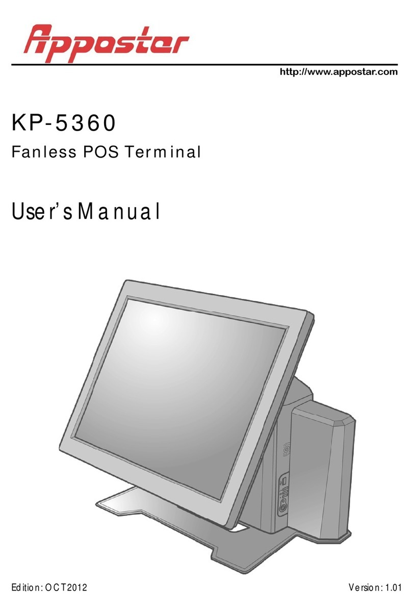
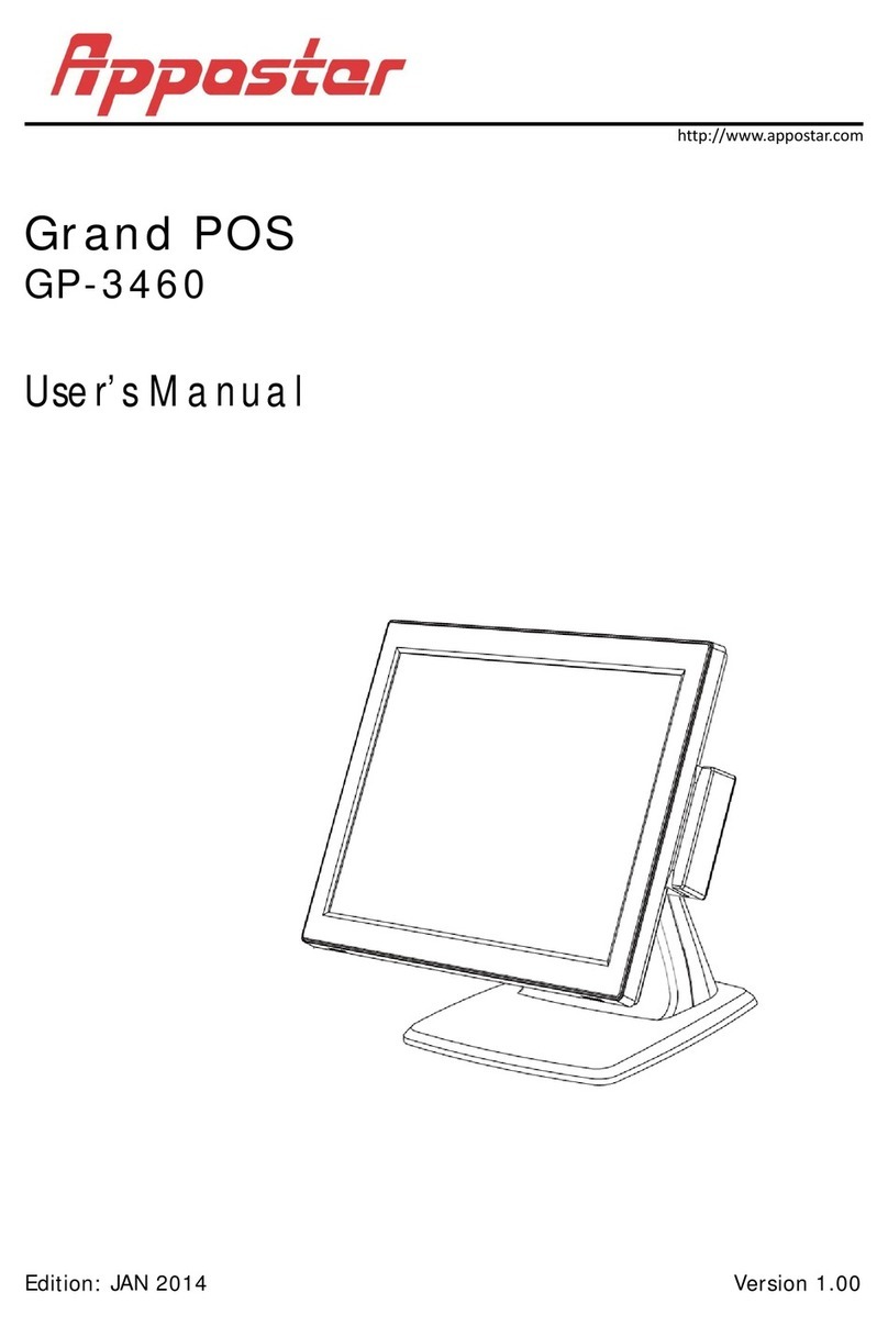
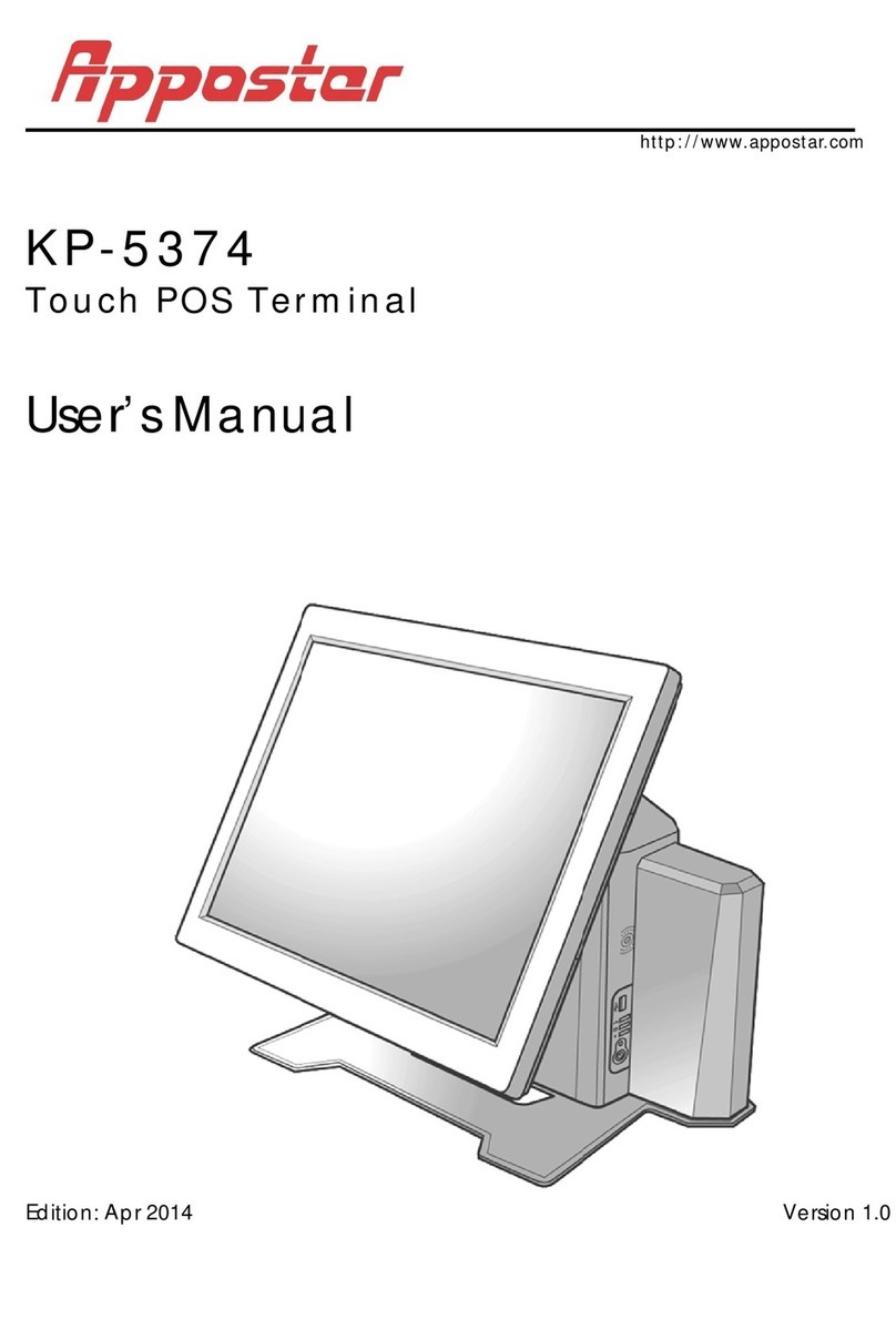
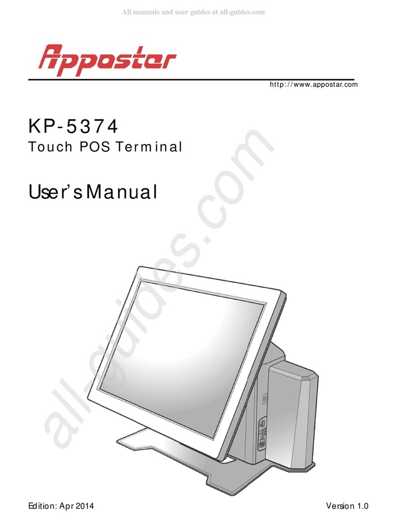
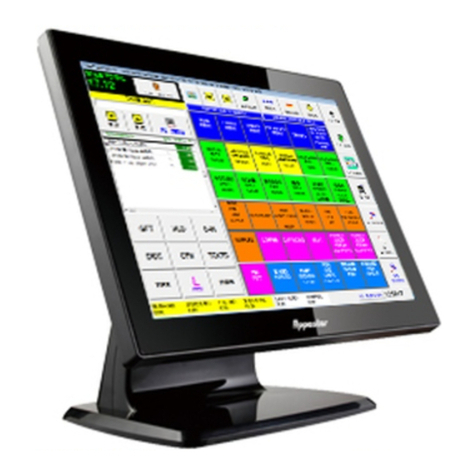
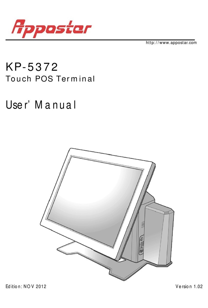
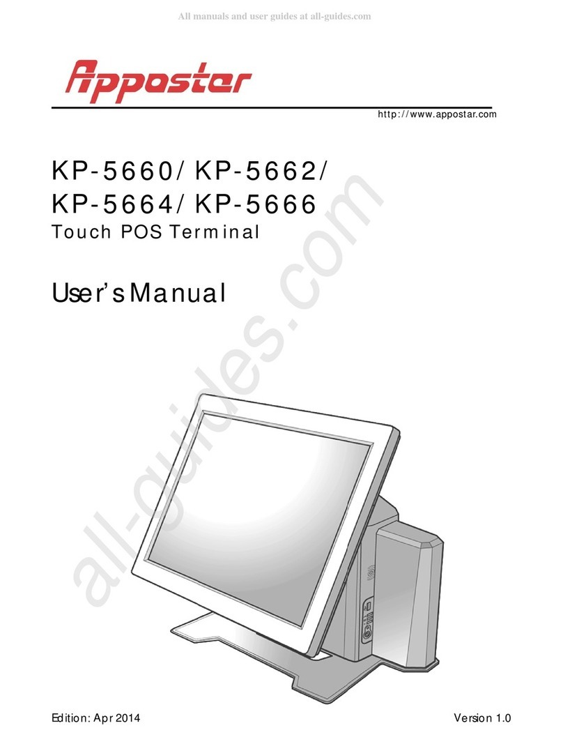
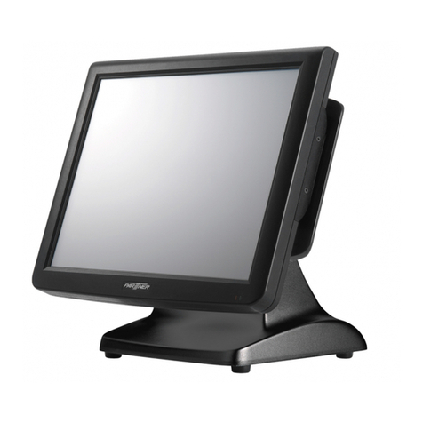
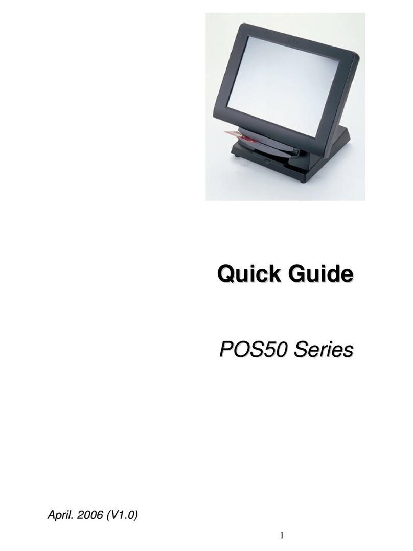
Appostar GP-3472 User manual

http://www.appostar.com
Grand POS
GP-3472/GP-3474/GP-3476
User’s Manual
Edition:Jan 2015 Version 1.0

PREFACE
II
Fede
r
This eq
u
di
g
ital d
e
provide
installati
ener
g
y
a
cause
h
g
uarant
e
equipm
e
can be
d
to try to
Decla
These d
e
followin
g
1. Th
e
2. Th
e
th
a
Lithi
u
To avoid
lithium
b
the man
WEEE
The WE
E
the pro
d
responsi
approve
d
For mor
e
please
c
where y
o
r
al Co
m
u
ipment h
e
vice, pu
r
reasona
b
i
on. This
a
nd, if n
o
h
armful i
n
e
e that i
e
nt does
c
d
etermin
e
correct t
h
Reorien
t
Increas
e
Connect
which t
h
Consult
ration
e
vices co
m
g
two con
d
e
se devic
e
e
se devic
e
a
t may ca
u
m Bat
possible
b
attery.
R
n
ufacture
r.
(Was
t
E
E wheel
e
d
uct mus
t
bility to
d
locatio
n
e
inform
a
c
ontact y
o
o
u purch
a
m
muni
c
as been
t
r
suant to
b
le prot
e
equipm
e
o
t install
e
n
terferen
c
nterferen
c
c
ause har
m
e
d by tur
n
h
e interf
e
t
or reloc
a
e
the sep
a
the equi
h
e receive
the deale
of Co
n
m
ply wit
h
d
itions:
e
s may n
o
e
s must
a
use unde
s
tery R
e
dan
g
er
o
R
eplace o
n
r.
t
e fro
m
e
d bin sy
m
t
not be
d
dispose
o
n
for the
a
tion abo
u
o
ur local
a
sed the
p
c
ation
s
ested an
d
part 15
o
e
ction a
ga
e
nt
g
ene
r
e
d and u
s
c
e to ra
d
c
e will n
m
ful inte
r
n
in
g
the
e
rence by
a
te the re
c
a
ration be
p
ment in
t
r is conn
e
r or an e
x
n
formi
t
h
part 15
o
t cause
h
a
ccept an
y
s
ired ope
r
e
plac
e
o
f explosi
o
n
ly with t
h
m
Elect
r
m
bol on
t
d
isposed
o
f their
w
r
ecyclin
g
u
t where
city offic
e
p
roduct.
G
s
Com
m
d
found t
o
o
f the FC
C
a
inst ha
r
r
ates use
s
s
ed in ac
c
d
io com
m
ot occur
r
ference t
o
e
quipmen
t
one or m
c
eivin
g
a
n
e
tween th
e
t
o an out
l
e
cted.
x
perience
d
t
y
of the F
C
h
armful i
n
y
interfer
e
r
ation.
e
ment
o
n, ensur
e
h
e same
r
ical a
n
t
he produ
of with
o
w
aste eq
of waste
to send
y
e
, your
h
G
P-3472/
G
m
issio
o
comply
w
C
Rules.
T
r
mful int
e
s
and c
a
c
ordance
m
unicatio
n
in a pa
r
o
radio o
r
t
off and
ore of th
e
n
tenna.
e
equipm
e
l
et on a
c
d
radio/T
V
C
C Rules.
n
terferen
c
e
nce rec
e
e
correct
o
r equiva
n
d Ele
c
ct or on
i
o
ther wa
s
uipment
electrical
y
our was
t
h
ousehold
G
P-3474/G
P
n (FC
C
w
ith the l
T
hese limi
t
e
rference
a
n radiat
e
with the
n
s. How
e
r
ticular i
n
r
televisio
n
on, the
u
e
followin
g
e
nt and r
e
c
ircuit diff
e
V
technici
a
Operatio
n
c
e.
e
ived, incl
polarity
w
lent type
c
tronic
ts packa
g
te. It sh
o
by hand
i
and ele
c
t
e equip
m
waste d
P
-3476 PO
S
C
)
imits for
a
ts are de
s
in a r
e
e
radio f
r
instructi
o
e
ver, the
n
stallatio
n
n recepti
o
u
ser is en
c
g
measur
e
e
ceiver.
e
rent fro
m
an for he
l
n
is sub
je
udin
g
int
e
w
hen cha
n
r
ecomm
e
Equip
m
g
in
g
indic
o
uld be t
h
in
g
it ov
e
c
tronic eq
m
ent for
r
d
isposal s
e
S
Terminal
a
Class A
s
i
g
ned to
e
sidential
r
equency
o
ns, may
r
e is no
n
. If this
o
n, which
c
oura
g
ed
e
s:
m
that to
l
p.
e
ct to the
e
rference
ng
in
g
the
e
nded by
m
ent)
ates that
h
e user’s
e
r to an
uipment.
r
ecyclin
g
,
e
rvice or

PREFACE
GP-3472/GP-3474/GP-3476 POS TerminalIII
Disclaimer
The material in this document is for information purpose and is subject to change
without prior notice. APPOSTAR has made every effort to ensure that this user’s
manual is accurate and complete. However, no liability is assumed for any errors
and omissions that may have occurred. Nor are any liability assumed for any
damages resulting from the use of this product and the information contained in
this document. APPOSTAR reserves the right to make improvements to this
publication from time to time in the contents hereof without obligation of the
manufacturer to notify any person of such revision or changes.
Copyright
This work is copyrighted. Reproduction or retransmission of this documentation,
in whole or in part, without prior written permission from the manufacture is a
violation of copyright law.
© 2015 APPOSTAR Technology Co., Ltd. All rights reserved.
Trademark Recognition
1. Microsoft, MS-DOS and Windows are registered trademarks of Microsoft
Corp.
2. Intel is a registered trademark of Intel International Inc.
3. Other software or product names used in this manual are the properties of
their respective owners and are acknowledged.

PREFACE
IVGP-3472/GP-3474/GP-3476 POS Terminal
Important Safety Instructions
Ignore these safety instructions may cause bodily injury, or damage to the
product. Read these instructions carefully and keep this user’s manual in an
accessible location for future reference.
1. Do not plug in or unplug the power cord with wet hands.
2. Do not plug the product into an AC outlet with the incorrect voltage.
(Be sure to use a voltage that is between AC 100V~240V)
3. Do not plug several products into one multi-outlet.
4. Do not apply pressure to the power cord or place heavy objects on it.
5. Immediately stop using the product if it emits strange noise, odor, or
smoke.
6. Do not use aerosol sprayers containing flammable gas inside or around
the product.
7. Do not allow foreign objects or liquids to enter the product, or serious
damage may result.
8. Do not place the product on an unstable surface. The product may cause
a fire if it is dropped, damaged, or broken.
The following instructions will help you to make better use of this product.
1. Keep the machine away from locations subject to high humidity, dust, or
temperatures that exceed the specification. (Refer to SEC. 1.4
Specification)
2. Clean the product only by using a dry cloth or a cloth soaked with
detergent. Never use thinner or other volatile solvents for cleaning.
3. At the end of the day, clean and inspect the exterior of the machine after
the machine is powered off.
4. Use only specified accessories.
5. Do not expose the accessories directly to sunlight, high temperatures,
humidity, dust, or gas.
6. Do not place heavy objects on top of the product or lean them against the
product. These items may fall down and cause injury.
7. Do not block the air vent of the product as this can cause heat
accumulation inside the box machine and may cause a fire.
Theproductmaycauseafireorelectricshockwhenitisusedimproperly.Observethesafety
measuresatalltimes.
Iftheproductisdamaged,immediatelyturnoffthepoweranddisconnectthepowercord.Contact
yourdealerforassistance.
Table Of Contents
CHAPTER 1 PRODUCT OVERVIEW.............................................................2
1.1 UNPACKING...................................................................................2
1.2 APPEARANCE.................................................................................3
1.3 I/O INTERFACE .............................................................................5
1.4 SPECIFICATION .............................................................................6
CHAPTER 2 HARDWARE INSTALLATION...................................................7
2.1 MAGNETIC STRIPE READER (MSR) INSTALLATION .............................7
2.2 VFD/LCD CUSTOMER DISPLAY INSTALLATION ...................................8
2.3 SECOND LCD INSTALLATION ...........................................................9
CHAPTER 3 SOFTWARE INSTALLATION.................................................10
3.1 MAINBOARD DRIVER INSTALLATION .............................................. 10
3.2 PERIPHERAL DEVICE DRIVER INSTALLATION................................... 12
CHAPTER 4 BOARD SETTING ..................................................................12
4.1 MAIN BOARD JUMPER SETTING ..................................................... 12
CHAPTER 5 TROUBLESHOOTING.............................................................14

PRODUC
T
2
CHA
P
Welc
o
The Gra
save po
w
Grand
P
value.
T
monitor
.
arran
g
e
m
match t
h
1.1 U
n
Confirm
missin
g
1. PO
S
(or
d
4. Qui
c
T
OVERVIE
W
P
TER
1
o
me
nd POS
s
w
er cons
P
OS inclu
d
T
he main
.
The c
o
m
ent. Up
h
e mood
o
n
packin
g
that all
t
or dama
g
S
Termina
d
ered sp
e
c
k Refere
W
1
PR
O
s
eries is t
h
umption
t
d
es ener
g
board o
f
o
mpact
a
to five
c
o
f the op
e
g
t
he follo
w
g
ed, cont
a
l Main Un
e
cification
)
nce Guid
e
O
DUC
T
h
e All-in-
O
t
o meet
t
g
y savin
g
f
Grand
P
a
nd solid
c
olor opti
e
ration e
n
w
in
g
item
s
a
ct the de
it
)
2
e
(Use
r
G
T
OVE
R
O
ne POS
t
he trend
, low noi
P
OS is s
k
d
stand
ons for t
n
vironme
n
s
are co
n
e
aler from
. Power
A
5. Drive
r
’s Manua
G
P-3472/
G
R
VIE
W
Terminal
for gre
e
se opera
t
k
illfully e
m
g
ives y
o
he front
n
ts.
n
tained in
whom y
o
A
dapter
r CD
l include
d
G
P-3474/G
P
W
which is
n produc
t
t
ion and
m
bedded
o
u flexibl
e
panel ar
e
the cart
o
o
u purcha
3
d
)
P
-3476 PO
S
concept
u
c
t. The fe
a
hi
g
h per
f
in the sl
e worki
n
e
also pr
o
on. If an
y
sed the
p
3
. Power
c
S
Terminal
u
alized to
a
tures of
f
ormance
im touch
ng
space
o
vided to
y
item is
p
roduct.
c
ord

PRODUCT OVERVIEW
GP-3472/GP-3474/GP-3476 POS Terminal3
1.2 Appearance
Front View
Rear View
15” LCD
touch panel
Front bezel
Base
MSR module (optional)
I/O Cover
Hinge cover
Storage for power adaptor

PRODUCT OVERVIEW
4GP-3472/GP-3474/GP-3476 POS Terminal
Side View
Tilt angle 0 ~ 85 degree
Left View
85°
Quick access slot for
USB Type A

GP-3472
/
1.3 I
/
No
NOTE:
W
t
h
/
GP-3474/
G
/
O Inte
r
Port
SPEAKE
R
DC Inpu
t
Cash Dra
w
(Di
g
ital I/
O
COM3 CO
M
COM5 CO
M
USB
Audio-in
Printer P
o
To
a
Re
m
W
ith the re
m
h
e slot.
G
P-3476 P
O
r
face
D
R
1.5W
t
12V/
2
w
er
O
) Di
g
ita
RJ11
C
(sin
g
l
e
M
1
M
2 Serial
and R
J
USB
2
Conn
e
Line-i
n
Jack
o
rt Parall
e
DB25
/
a
void confu
s
m
ove the lid
m
ovable HD
D
O
S Termin
a
escripti
o
inte
g
rated
.5A DC Ja
c
l I/O with
1
C
onnector
e
/dual)
port with
D
J
-45 Conn
e
2
.0 A-type
e
ctor x 4
n
with Aud
i
e
l port wit
h
/
F Connec
t
s
ion with th
e
before use
D
/ SSD br
a
a
l
o
n N
x 2
c
k
1
2V
D
B9/M
e
ctor
i
o
h
t
or
e LAN port,
e
.
a
cket, the
H
o
P
o
S
w
VG
A
P
S
L
A
Aud
i
DC
O
St
o
the COM 5
H
DD / SSD
c
P
o
rt
w
itch
P
A
-OUT
D
s
S
/2
P
M
A
N
R
i
o-out
L
J
O
utpu
t
1
o
ra
g
e
H
r
is protecte
c
an be easil
y
P
RODUCT
O
Descr
i
P
ower on/
o
D
B15/F VG
s
econd dis
p
P
S/2 Keyb
o
M
ouse Con
R
J45 LAN
C
L
ine-out wi
J
ack
1
2V/ 2A D
C
H
DD or SS
D
r
emovable
e
d with a lid
y removed
O
VERVIEW
5
i
ption
o
f
f
A for
p
lay
o
ard &
nector
C
onnector
th Audio
C
Jack
D
with
bracke
t
.
from

PRODUCT OVERVIEW
6GP-3472/GP-3474/GP-3476 POS Terminal
1.4 Specification
Model Name GP-3472 GP-3474 GP-3476
System
Main Board IVP-76HM
CPU i3 3110M 2.4GHz i5 3230M 3.2GHz i7 3630QM 3.4GHz
Chipset Intel HM76 Express
Memory 1GB DDRIII RAM
Display Size 15” TFT-LCD with LED backlight
Display Resolution 1024 x 768
Touch Panel 5 wire resistive touch
HDD 2.5” SATA HDD 320G
Expansion slot 1 x Mini PCIe
OS Support POSReady 2009, POSReady7, Windows XP / XPE, Windows 7,
Windows 8, Linux
Power AC 100V~240V / 90W adapter
External I/O Interface
Serial Port 4 x External COM Ports with 5V /12V selectable
Cash Drawer Port 1 x RJ11 with DC 12V(Standard/24V)
Keyboard Port 1 x PS/2(Keyboard or Mouse)
VGA Port 1 x VGA (DB15)
Audio Port 1 x Line in, 1x Line out
Speaker 2 x Integrated 1.5W Stereo Speaker
Ethernet Port 1 x RJ45 10M / 100M / 1G Base-T
Parallel Port 1 x Bi-directional Parallel (Standard)
USB Port 3 x USB 2.0 + 2 x USB 3.0 Type A
DC output Jack 1 x 12V / 2.5A
Power Button 1 x power on / off switch
Optional Peripheral
Magnetic Card Reader ISO 7811 option 1 / 2 / 3 track
Finger Print 512 dpi x 8 bit gray scale, Capture area: 14.6 x 18.1 mm
i-Button Dallas Key
Wireless LAN 802.11 b/g
Customer Display VFD / LCD Customer Display
Second Display 8" / 11.6" / 15" TFT-LCD display/non-touch
Environment
EMC & Safety CE / FCC Class A
Operating Temperature 5°C ~ 40°C
Storage Temperature -20°C ~ 60°C
Operating Humidity 15% ~ 80% RH
Storage Humidity 20% ~ 90% RH
Mechanical
Housing Color Black
Construction ABS + SECC
Dimension(W x D x H) 350 x 242 x 320 mm
Weight 5.8 kg

HARDWARE INSTALLATION
GP-3472/GP-3474/GP-3476 POS Terminal7
CHAPTER 2 HARDWARE INSTALLATION
Before starting any hardware configuration, ensure that the system is powered
off and the power cord is disconnected to prevent possible damage to the product.
2.1 Magnetic Stripe Reader (MSR) Installation
An optional MSR can be installed at right side of GP-3462.
Step 1
Remove the cover from the MSR expansion slot.
Step 2
Connect the MSR cable correctly.
Step 3
Fix the MSR module in position with 2 screws.
①
②
③

HARDWARE INSTALLATION
8GP-3472/GP-3474/GP-3476 POS Terminal
2.2 VFD/LCD Customer Display Installation
Step1
Use flat screw driver to remove the stand cover and break up the lid at the
bottom of the cover.
Step2
Fit in the bracket and screw it tight.
Step3
Install the VFD onto the bracket and lead the cable through the stand to the
RJ45 COM port.
①
②
③

HARDWARE INSTALLATION
GP-3472/GP-3474/GP-3476 POS Terminal9
2.3 Second LCD Installation
Step1
Use flat screw driver to remove the stand cover and break up the lip at the
bottom of the cover.
Step2
Fit the bracket in position with 2 screws.
Step3
Reinstall the stand cover.
Step4
Hang the LCD onto the bracket and REMEMBER to screw it tight.
Step5
Connect the VGA and power cable to the main screen.
①
②
③
④
⑤

SOFTWARE INSTALLATION
10GP-3472/GP-3474/GP-3476 POS Terminal
CHAPTER 3 SOFTWARE INSTALLATION
This chapter describes the driver requirements and how to install the drivers from
the driver CD. All step-by-step procedures described below are for Windows XP
and similar on all other Microsoft Windows platforms.
Insert the driver CD into your CD-ROM drive. Windows will automatically detect
it and the Appostar Driver Installer appears on the screen. If not, locate the
Setup.exe file at CD:\ and double-click it to execute the one-step driver
installation. Follow the on-screen instructions to complete the installation.
3.1 Mainboard Driver Installation
a.PleaseselectyourmodelnameandclickNEXTtocontinue.
b. ClickDriversiconontheupperleftcornerto
continue.
c. Selectthe“Drivers”option.ClickInstallto
continue.
d. Installationprogramwillextractdriverfiles
toinstall.
e. AfterChipsetDriver(INF)installed,clickNo
tocontinue.

BOARD SETTING
GP-3472/GP-3474/GP-3476 POS Terminal11
f. Select“Installthisdriversoftwareanyway”
inWindowsSecuritywindowtocontinue
theinstallationprocedure.
g. Select“Install”inWindowsSecuritywindow
tocontinuetheinstallationprocedure.
h. Select“Yes”torebootsystem.

SOFTWARE INSTALLATION
12GP-3472/GP-3474/GP-3476 POS Terminal
3.2 Peripheral Device Driver Installation
3.2.1 Touch COM Driver Installation
a. Click Peripheral Devices b. Click Touch Panel.
c. Click Next on the Welcome screen
to continue. d. Ignore the “Install PS/2 interface
driver” option. Click Next to
continue.
e. Select the “Install RS232 interface
driver” option. Click Next to
continue.
f. Select the None option and click
Next to continue.

SOFTWARE INSTALLATION
GP-3472/GP-3474/GP-3476 POS Terminal13
g. Select the “Support Multi-Monitor
System” option. Click Next to
continue.
h. Select the Destination Folder or
use the default one listed.
i. Type a Folder name or use the
default one listed. Click Next to
continue.
j. A progress window appears. Please
wait.
k. Click Yes. The installation
completes in seconds.

BOARD SETTING
14GP-3472/GP-3474/GP-3476 POS Terminal
CHAPTER 4 BOARD SETTING
4.1 Main Board Jumper Setting
JCMOS1: Clear CMOS Jumper *
Placing the jumper on pin2-3 allows user to restore the BIOS safe setting
and the CMOS data. Please carefully follow the procedures to avoid
damaging the motherboard.
※Clear CMOS Procedures:
1. Remove AC power line.
2. Set the jumper to “Pin 2-3 close”.
3. Wait for five seconds.
4. Set the jumper to “Pin 1-2 close”.
5. Power on the AC.
6. Reset your desired password or clear the CMOS data.
Serial Port Voltage Switch for COM1 / COM2 through BIOS setting
Enter BIOS / Advanced / F81866 Super IO Configuration / UART1 RI
Function for COM1 or UART2 RI Function for COM2
31
Pin 1-2 Close:
Normal Operation
(Default).
3
1
Pin 2-3 Close:
Clear CMOS data.

BOARD SETTING
GP-3472/GP-3474/GP-3476 POS Terminal15
JPC4:Serial Port Voltage Switch Jumper for JCOM4
Pin 1-2 Close: Pin 9=0V
Pin 3-4 Close: Pin 9=5V (Default)
Pin 5-6 Close: Pin 9=12V
JCOM3 / JCOM5 / JCOM6: Serial Port Headers
Pin
Assignment Pin Assignment
1 DCD 2 RXD
3 TXD 4 DTR
5 GND 6 DSR
7 RTS 8 CTS
9 0V/5V/12V 10 NA
JPC3 / JPC5 / JPC6: Serial Port Voltage Switch Jumper for JCOM3
/ JCOM5 / JCOM6
Pin 1-2 Close: Pin 9=0V (Default)
Pin 3-4 Close: Pin 9=5V
Pin 5-6 Close: Pin 9=12V

TROUBLESHOOTING
16GP-3472/GP-3474/GP-3476 POS Terminal
Chapter 5 TROUBLESHOOTING
This chapter provides suggestions on how to locate and solve problems that may
arise while using your GP-3462. If you cannot solve a problem with the following
information, contact your dealer for further assistance.
With the power on, there is no image or abnormal display on the
terminal screen.
A. Make sure the power cord is firmly connected.
(Ensure the AC voltage range should be between 100V~240V.)
B. Confirm the function of the power adapter by testing another one.
UATTENTION
If step A, B do not help and the problem remains unsolved, contact your dealer
for further assistance.
The Touch Panel is not working properly.
1. Check whether the Touch Panel Driver has been correctly installed in the PC.
2. If the touch panel can detect the finger touch but the cursor is drifting, use
the touch tool (from the Driver CD) to execute calibration or draw test.
The Integrated VFD/LCD display is not working properly.
1. Make sure the power switch under the display panel is turned on.
2. Make sure the contrast setting is properly adjusted.
3. Make sure the RJ45 connector is firmly connected to the COM2 (RJ45) port
at the bottom side of the monitor and the jumper is set to DC 5V. See page
24 for the jumper setting.
The Magnetic Stripe Reader is not working properly.
1. Check whether the MSR is powered properly by the system: if the buzzer
beeps twice after restarting the system, it means the MSR is powered
correctly.
2. Test the reader with another card. If that works, the MSR is functioning
properly.
3. Wipe the MSR slot with a soft cloth then try again.
NOTE:
If the problem goes beyond the scope of this manual or remains unresolved, DO
NOT repair it by yourself, contact your dealer for assistance.
This manual suits for next models
4
Table of contents
Other Appostar Touch Terminal manuals

Appostar
Appostar BS-6500 User manual

Appostar
Appostar KP-5374 User manual

Appostar
Appostar FP-4266 User manual

Appostar
Appostar NP-3262 User manual

Appostar
Appostar KP-5370 User manual

Appostar
Appostar Grand POS GP-3464 User manual

Appostar
Appostar GP-3460 User manual

Appostar
Appostar KP-5562 User manual

Appostar
Appostar KP-5660 User manual

Appostar
Appostar KP-5660 User manual