BEGA BETEX EP13 Series User manual

© Bega International BV, Oct. 2015
Assembly Manual
BETEX®EP13, EP18 & EP211 series
Electric hydraulic pumps
READ THE ASSEMBLY MANUAL AND SAFETY INSTRUCTIONS
BEFORE OPERATING THE DEVICE
Check all parts for possible transport damage.
In case of damage, please contact the carrier immediately.


1. User manual
2. Gebrauchsanleitung
3. Manuel del usario
4. Manuel de l‘utilisateur
..
5. Gebruiksaanwijzing ..
READ THE MANUAL AND SAFETY INSTRUCTIONS
Check all parts for possible transport damage.
If any damage is apparent, inform carrier immediately.
GEBRAUCHSANLEITUNG UND SICHERHEITSHINWEISE BITTE SORGFÄLTIG LESEN
Bitte kontrollieren Sie den Inhalt auf Transportschäden. Falls Sie Schäden entdecken,
informieren Sie bitte umgehend das Transportunternehmen.
LEA EL MANUAL Y LAS INSTRUCCIONES DE SEGURIDAD
Compruebe todas las piezas por si hubieran sido dañadas durante el transporte. Si hay
daños, informe al transportista inmediatamente.
VEUILLEZ LIRE LE MANUEL EN CONSIGNES DE SÉCURITÉ
Vérifier le bon état de tous les éléments afin de s’assurer qu’ils ne sont pas endommagés.
En cas de dommage, veuillez informer immédiatement à réception le transporteur.
LEES DE GEBRUIKSAANWIJZING EN VEILIGHEIDSVOORSCHRIFTEN
Controleer alle onderdelen op mogelijke transport schade. Schade dient direct aan de
transporteur gemeld te worden.
GB
D
E
F
NL
GB
D
E
F
NL
3
GB
D
E
F
NL
3
1. User manual
2. Gebrauchsanleitung
3. Manuel del usario
4. Manual de l’utilisateur
5. Gebruiksaanwijzing
© Bega International BV, Oct. 2015
Assembly Manual
BETEX®EP13, EP18 & EP211 series
Electric hydraulic pumps
READ THE ASSEMBLY MANUAL AND SAFETY INSTRUCTIONS
BEFORE OPERATING THE DEVICE
Check all parts for possible transport damage.
In case of damage, please contact the carrier immediately.

INDEX
English .................................................................................... 5
Deutsch ................................................................................... 18
Espagnol ................................................................................. 31
Francais .................................................................................. 44
Nederlands .............................................................................. 57
4

Bega International BV –Assembly Manual Betex® EP13, EP18 & EP211 series –Oct. 2015
3
1. INTRODUCTION
1.1 Application
Betex® EP13, EP18 and EP211 series electric hydraulic pumps are for driving hydraulic systems. The pumps
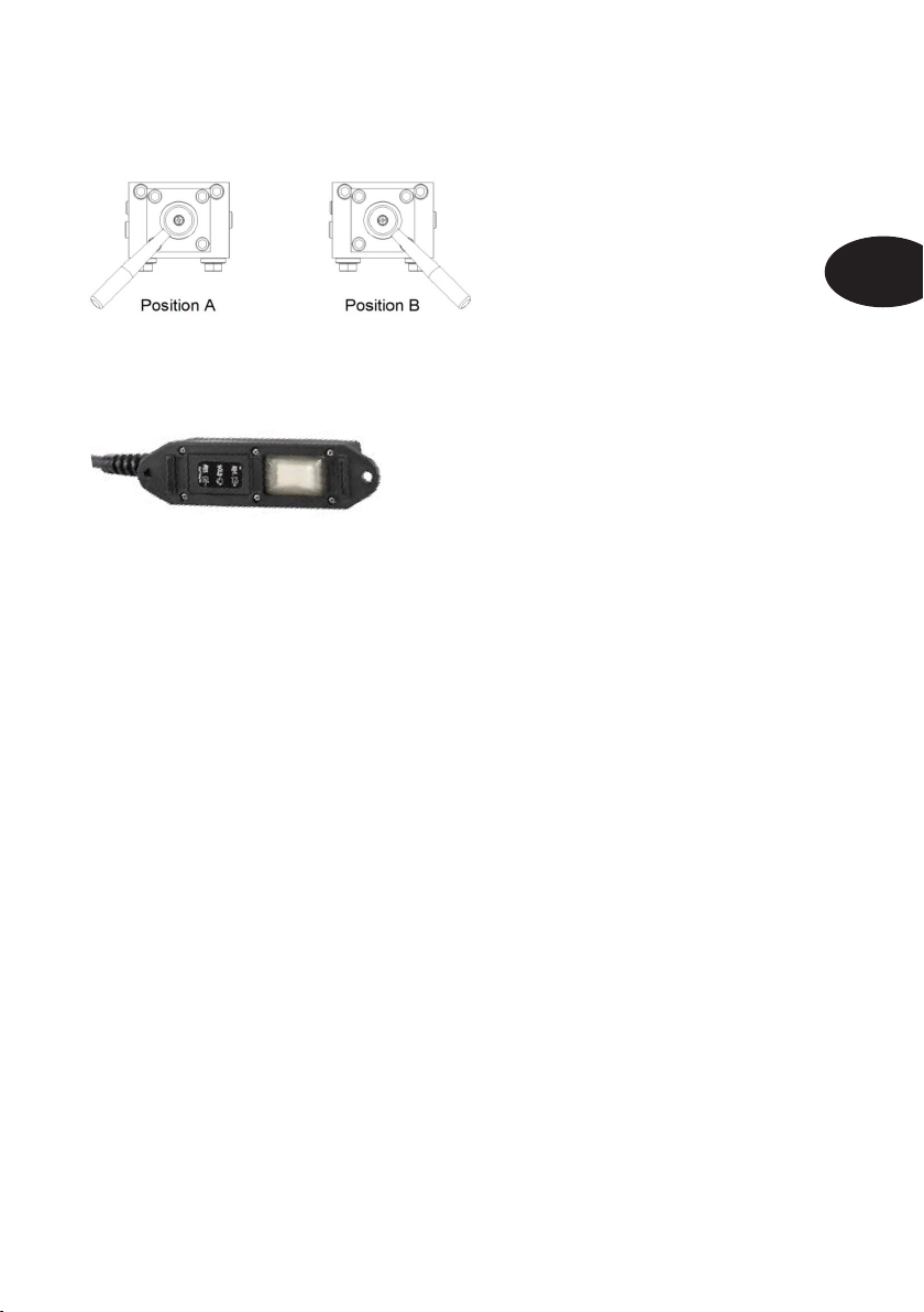
are equipped with an on/off switch, emergency stop and remote control. The pumps are supplied without oil in
the reservoir.
1.2 Application areas
Betex® EP13, EP18 and EP211 series electric hydraulic pumps are suitable for use in an industrial
environment. The pumps are not suitable for explosive, highly flammable or corrosive environments. Using the
pumps in a medical or humid (>90%) environment is not permitted.
1.3 Principles of operation
Betex® EP13, EP18 and EP211 series electric hydraulic pumps work with a displacement pump which brings
the hydraulic oil to a maximum pressure of 700 Bar (10,000 PSI). This displacement pump is powered by an
electrical motor. The electrical energy is converted into hydraulic energy by the electric hydraulic pump. A pre-
mounted valve allows one to connect the electric hydraulic pump to fittings which convert the hydraulic energy
into, for example, mechanical energy, depending on the application.
2. SAFETY
2.1 Warnings
Do not use the electric hydraulic pump in an explosive or highly flammable environment.
Connecting fittings that are unable to cope with the maximum pressure (700 Bar/10,000 PSI) is not
permitted.
Check whether the pump is safely connected to all the fittings used and whether the installation can be
operated safely before operating the electric hydraulic pump.
The electric hydraulic pump may not be used outdoors.
2.2 Safety risks
Pressurized fluid: risk of oil injection in case of a leak.
Noise level 81dBA
Electrocution by incorrect earthing of the electric hydraulic pump.
2.3 Safety provisions
Emergency stop
On/off switch
Overpressure valve set to 700 Bar (10,000 PSI)
2.4 Inadvisable use
Do not use the electric hydraulic pump at pressures higher than 700 Bar (10,000 PSI).
Do not use the electric hydraulic pump in places where the pump can come into contact with liquids.
2.4 Safety measures (to be applied by the user)
When the electric hydraulic pump is used in an installation where something moves in a vertical plane,
hose rupture protection must be fitted directly to the lifting cylinder.
The electric hydraulic pump must always be properly connected to an earthing conductor. The electric
hydraulic pump may not be turned on when this is not present.
Electric hydraulic pumps with single-function valves (pumps without a ‘D’ or ‘DS’ suffix) may not be
connected to a double-function cylinder, unless measures are taken to prevent overpressure in the cylinder.
The complete installation must be checked to see whether it satisfies the minimum safety requirements of
the most recent version of the Machinery Directive. Then a presumption of conformity must be drafted,
before the installation is operated, according to appendix 2A of the Machinery Directive.
5
GB

Bega International BV –Assembly Manual Betex® EP13, EP18 & EP211 series –Oct. 2015
4
3. ASSEMBLY, INSTALLATION AND COMMISSIONING
3.1 Remove packaging and place pump.
Remove all the packaging material. Check all parts for damage. In case of damage, contact the carrier
immediately. Sort and dispose of the packaging material properly to protect our environment. Ensure that the
electric hydraulic pump is installed properly, so that it cannot move during operation which could pull on the
hydraulic and electrical connections.
3.2 Connecting
3.2.1 Electrical connection
Check that the values on the type plate correspond with the values of your connection. The pump can be
connected when these values are the same. Conversion kits are also available to convert the pump from 230V
to 120V or from 120V to 230V. See paragraph 5.1 for the article numbers.
3.2.3 Hydraulic connections
All hydraulic ports are provided with 3/8” female NPT thread. Only connect fittings to them with 3/8” male NPT
thread.
Single-function:
The connections in the red circle are the ports that are placed under pressure when the pump is turned on and
the lever points to ‘ADV’ (Advance). In the case of ‘Solenoid’ valves (EP18SS / EP211SS), this port is placed
under pressure when the button on the remote control is pressed. Preferably use the port with the plastic cap.
The port that is not used must be properly sealed with a steel sealing plug. The port in the yellow circle is not
under pressure. This can be used when a single-function cylinder must be bled.
Double-function
The 2 ports in the red circle are port A. The 2 ports in the yellow circle are port B. Preferably use the port with
the plastic cap. The port that is not used must be properly sealed with a steel sealing plug.
6

Bega International BV –Assembly Manual Betex® EP13, EP18 & EP211 series –Oct. 2015
5
EP13D / EP18D / EP211D:
When the pump lever is in position A and the button of the remote control is pressed, port A is put under
pressure. Port B is not under pressure. When the lever is in position B and the button of the remote control is
pressed, port B is put under pressure. Port A is not under pressure. See the drawing below for the position of
the lever:
EP18DS / EP211DS:
When the ‘Advance’ (A) button on the remote control is pressed, port A is placed under pressure and port B is
not under pressure. When the ‘Return’ (B) button on the remote control is pressed, port B is placed under
pressure and port A is not under pressure.
3.3 Trial run
The machine is supplied without oil. The hydraulic oil provided is suitable for most applications. Special
hydraulic oil must be used for applications with lower ambient temperatures. The reservoir must be filled before
the machine can be trial run:
1. Clean the pump around the filling opening to avoid getting dirt in the reservoir.
2. Remove the filler cap.
3. Use a clean funnel with a filter to fill the pump.
4. Fill the pump with new hydraulic oil. EP13 = 3L, EP18 = 8L, EP211 = 11L. The oil level should be 1.5 to
2 cm under the lid.
5. Remove the funnel and put the filler cap back on. Screw it on properly, but not too tight. The rubber
washer ensures a good seal. Check that the valve in the filler cap is open. This stops pressure building
up in the reservoir.
6. Bleed all fittings before operating the system. Running the system under full pressure for a while is
recommended. By doing so, everything is run at maximum capacity, and one can easily check whether
all the connections are properly sealed. Never attempt to stop hydraulic oil from leaking with part of your
body. Do not 'touch' seals to check for leaks. Oil injected under the skin may result in the loss of body
parts.
A
B
7
GB

Bega International BV –Assembly Manual Betex® EP13, EP18 & EP211 series –Oct. 2015
6
4. CLEANING AND MAINTENANCE
4.1 Cleaning
The system must be turned off and the plug must be removed from the socket before the electric
hydraulic pump may be cleaned.
The electric hydraulic pump may be cleaned with a damp cloth. A mild detergent solution is permitted for
removing oil or stubborn dirt. Do not use corrosive agents as they can damage the hydraulic
connections.
Fit the rubber protective cover to prevent dust when quick couplings are not used.
Prevent all possible contamination of the system.
4.2 Maintenance
Maintenance must be performed by qualified and certified personnel at all times!
The electric hydraulic pump must be turned off and the plug must be removed from the socket before
maintenance may be performed.
4.2.1 Hydraulic oil
1. Check the hydraulic oil level when all cylinders are retracted every 40 hours. Top up if needed (Section
3.3). The system must be checked for leaks if large quantities of oil must be regularly added.
2. Check the cleanliness of the hydraulic oil every 120 hours. The oil must be replaced if it becomes dirty.
Ensure that all cylinders are in the retracted position, tap off the oil and fill the reservoir again with
hydraulic oil (Section 3.3).
3. Replace the hydraulic oil every 400 hours. Ensure that all cylinders are in the retracted position, tap off
the oil and fill the reservoir again with hydraulic oil (Section 3.3).
4.2.2 System
The nature and frequency of the system check must be determined by the person responsible for the
installation. The following points serve as a guideline.
1. Regularly check the system for leaks.
2. Regularly check the cylinders if cylinders are used. Nature and frequency according to the user
instructions for the cylinders.
3. Regularly check whether any fittings are bent or damaged. Damaged hydraulic fittings must be
immediately replaced to prevent accidents.
4. If hoses are used, check them regularly. Nature and frequency according to the user instructions for the
hoses.
5. TECHNICAL DATA
5.1 Conversion kits
Article number overview:
From 120V to 230V
From 230V to 120V
EP13S / 18S / 13D / 18D
830 0096
830 0090
EP18SS
830 0097
830 0091
EP18DS
830 0098
830 0092
EP211S / EP211D
830 0099
830 0093
EP211SS
830 0100
830 0094
EP211DS
830 0101
830 0095
8

Bega International BV –Assembly Manual Betex® EP13, EP18 & EP211 series –Oct. 2015
7
5.2 Dimensions, capacity and weights
EP13
EP18
EP211
Dimensions LxBxH
485 x 235 x 512 mm
491 x 312 x 504 mm
513 x 229 x 559 mm
Empty weight
26.5 kg
31 kg
37 kg
Connected load
230V/5A -120V/10A
230V/5A -120V/10A
230V/12A -120V/23A
Reservoir volume (usable)
3 (2.8) L
8 (6) L
11 (8.5) L
Maximum pressure
700 bar
700 bar
700 bar
Oil flow
At 0 bar
4.2 L/min
4.2 L/min
8.2 L/min
At 7 bar
3.1 L/min
3.1 L/min
7.4 L/min
At 350 bar
0.33 L/min
0.33 L/min
0.84 L/min
At 700 bar
0.26 L/min
0.26 L/min
0.65 L/min
Idling noise level
67 dBA
67 dBA
67 dBA
Operating noise level
81 dBA
81 dBA
81 dBA
Dimensional drawing EP13
9
GB

Bega International BV –Assembly Manual Betex® EP13, EP18 & EP211 series –Oct. 2015
8
Dimensional drawing EP18
Dimensional drawing EP211
10

Bega International BV –Assembly Manual Betex® EP13, EP18 & EP211 series –Oct. 2015
9
5.3 Parts drawing
Only original parts may be used. The warranty lapses if non-OEM parts are used.
EP13
Number:
Description:
Article number:
01
Valve single-function manually operated EP13/18/211
72000142
02
Valve gasket EP13/18/211
72000144
03
Valve double-function manually operated EP13/18/211
72000143
04a
Switch box EP13/18 230V
72000120
04b
Switch box EP13/18 120V
72000121
05
Remote control for manually-operated valve EP13/18/211
72000145
06
Electromotor EP13/18
72000122
07
Electromotor gasket EP13/18/211
72000147
08
Cover plate EP13 including pump
72000150
09
Handle AP/HP/EP18
72000151
10
Reservoir gasket AP/HP/EP18
72000152
11
Reservoir AP/HP/EP18
72000153
11
GB

Bega International BV –Assembly Manual Betex® EP13, EP18 & EP211 series –Oct. 2015
10
Only original parts may be used. The warranty lapses if non-OEM parts are used.
EP18
Number:
Description:
Article number:
01
Valve single-function electrically operated EP18/211
72000140
02
Valve double-function electrically operated EP18/211
72000141
03
Valve single-function manually operated EP13/18/211
72000142
04
Valve gasket EP13/18/211
72000144
05
Valve double-function manually operated EP13/18/211
72000143
06a
Switch box EP13/18 230V
72000120
06b
Switch box EP13/18 120V
72000121
07a
Remote control for manually-operated valve EP13/18/211
72000145
07b
Remote control for electrically-operated valve EP13/18/211
72000146
08
Electromotor EP13/18
72000122
09
Electromotor gasket EP13/18/211
72000147
10
Cover plate AP/HP/EP18 including pump
72000123
11
Handle AP/HP/EP18
72000124
12
Reservoir gasket AP/HP/EP18
72000125
13
Reservoir AP/HP/EP18
72000126
12

Bega International BV –Assembly Manual Betex® EP13, EP18 & EP211 series –Oct. 2015
11
Only original parts may be used. The warranty lapses if non-OEM parts are used.
EP211
Number:
Description:
Article number:
01
Valve single-function electrically operated EP18/211
72000140
02
Valve double-function electrically operated EP18/211
72000141
03
Valve single-function manually operated EP13/18/211
72000142
04
Valve gasket EP13/18/211
72000144
05
Valve double-function manually operated EP13/18/211
72000143
06a
Switch box EP211 230V
72000130
06b
Switch box EP211 120V
72000131
07a
Remote control for manually-operated valve EP13/18/211
72000145
07b
Remote control for electrically-operated valve EP13/18/211
72000146
08
Carrying handle EP211
72000134
09
Electromotor EP211
72000132
10
Electromotor gasket EP13/18/211
72000147
11
Aluminium back-up ring for electromotor EP211
72000137
12
Cover plate EP211 including pump
72000133
13
Reservoir gasket EP211
72000135
14
Reservoir EP211
72000136
13
GB

Bega International BV –Assembly Manual Betex® EP13, EP18 & EP211 series –Oct. 2015
12
5.4 Electrical circuit diagrams
Double-function electrically operated: Single-function electrically operated:
Double and single-function manually operated:
14

Bega International BV –Assembly Manual Betex® EP13, EP18 & EP211 series –Oct. 2015
13
Minimum core diameter of connecting cable:
5.5 Hydraulic drawings
EP13/18S EP13/18D EP18SS EP18D
EP211S EP211D EP211SS EP211DS
5.6 Flowcharts
EP13/18: EP211:
0-8 m
8-15 m
15-30 m
30-46 m
0-25 ft
25-50 ft
50-100 ft
100-150 ft
EP13/18 230V
0.75 mm²
1 mm²
1.5 mm²
2.5 mm²
18 AWG
16 AWG
14 AWG
12 AWG
EP13/18 120V
EP211 230V
0.75 mm²
1.5 mm² 2.5 mm² 4 mm² 18 AWG 14 AWG 12 AWG 10 AWG
EP211 120V
2.5 mm²
4 mm²
6 mm²
10 mm²
12 AWG
10 AWG
8 AWG
6 AWG
15
GB

Bega International BV –Assembly Manual Betex® EP13, EP18 & EP211 series –Oct. 2015
14
5.7 Solving possible problems:
Problem:
Cause:
Solution:
Electrical motor not working.
No power supply.
Check whether sufficient voltage is
available.
A cable is broken.
Check the cables for any breaks
and replace if necessary.
Motor defect.
Replace the motor.
The connecting cable is too long
or it does not have the right core
diameter.
Check whether the connecting
cable satisfies the minimum
requirements based on the table
on page 11. Replace this if
necessary.
Motor relay defect.
Replace the relay.
Safety fuse on circuit board has
melted.
Replace the safety fuse with a
safety fuse with the same
specifications.
The pump does not deliver any
hydraulic oil or delivers
insufficient hydraulic oil such
that the cylinder only partially
comes out or judders.
Too little hydraulic oil.
Top up the reservoir to 1.5 to 2 cm
under the lid.
Air in the system.
Bleed the system.
Suction filter blocked.
Remove the pump lid and clean
the filter.
Dirt in the system.
Remove the pump lid and
disassemble the system and clean
the inside of the pump.
Hydraulic oil has too high viscosity.
Replace the oil with a lighter oil.
Valve overpressure not set
properly.
Set the overpressure valve.
The pump generates insufficient
or too much pressure.
Check whether the manometer is
still OK.
Replace or calibrate the
manometer.
Check whether the system is
leaking.
Stop the leaks.
Overpressure valve is not set
properly.
Correctly set the overpressure
valve.
Cylinder(s) is/are not retracted.
The valve can stick when the
system is left under pressure.
Remove the pressure from the
system and replace the valve.
Take care with hydraulic oil that is
under pressure.
Cylinder sticks mechanically.
Remove the blockage.
The hose breaks away from the
cylinder and the cylinder is fitted
with hose rupture protection.
Fit a new hose, bring it up to
pressure and allow the cylinder to
return to normal.
The cylinder is rigged with quick
couplings and a quick coupling
has come off.
Reconnect the quick coupling.
Take care with hydraulic oil that is
under pressure.
6. DISPOSAL
6.1 In accordance with statutory regulations
All materials must be disposed of in accordance with statutory regulations.
All the oil must be removed and the plug must be cut off the connecting cable before disposing of the electric
hydraulic pump.
16

Bega International BV –Assembly Manual Betex® EP13, EP18 & EP211 series –Oct. 2015
15
MANUFACTURERS DECLARATION
complies with Appendix II B of the Machinery Directive
Manufacturer's name: Bega International BV
Manufacturer's address: Schorsweg 15
8171 ME Vaassen
The Netherlands
Hereby declares that the product: Betex® EP13S
Betex® EP13D
Betex® EP18S
Betex® EP18D
Betex® EP18SS
Betex® EP18DS
Betex® EP211S
Betex® EP211D
Betex® EP211SS
Betex® EP211DS
to which this declaration refers complies with the provisions of the following directives:
Low Voltage Directive
2006 / 95 / EC
EMC Directive
2004 / 108 / EC
Machinery Directive
2006 / 42 / EC
In which (parts of) the following standards are applied:
NEN-EN-IEC 60204-1/A1/C11 : 2010
NEN-EN-ISO 12100 : 2010
NEN-EN-ISO 4413 : 2010
Date: 01/10/2015
F. Garritsen
Director
Bega International BV
17
GB

Bega International bv –Montageanleitung Betex® EP13, EP18 & EP211 Serie –Okt. 2015
3
1. EINFÜHRUNG
1.1 Verwendungszweck
Die Elektro-Hydraulikpumpen der Serie Betex® EP13, EP18 und EP211 sind für den Antrieb von
Hydrauliksystemen bestimmt. Die Pumpen sind mit An-/Ausschalter, Notausschalter und Fernbedienung
ausgestattet. Die Pumpen werden ohne Öl im Behälter geliefert.
1.2 Verwendungsbedingungen
Die Elektro-Hydraulikpumpen der Serie Betex® EP13, EP18 und EP211 sind ausgezeichnet für den Einsatz in
industrieller Umgebung geeignet. Die Pumpen sind nicht für explosionsfähige, leicht entflammbare oder
korrosive Umgebungen geeignet. Die Verwendung der Pumpen in medizinischer oder feuchter (> 90 %)
Umgebung ist nicht zulässig.
1.3 Funktionsprinzip
Die Elektro-Hydraulikpumpen der Serie Betex® EP13, EP18 und EP211 arbeiten mit einer Verdrängerpumpe,
die das Hydrauliköl auf einen Maximaldruck von 700 bar (10.000 PSI) bringt. Diese Verdrängerpumpe wird von
einem Elektromotor angetrieben. Die elektrische Energie wird durch die Elektro-Hydraulikpumpe in hydraulische
Energie umgewandelt. Die Elektro-Hydraulikpumpe kann mit dem vormontierten Ventil an Armaturen
angeschlossen werden, die die Hydraulikenergie abhängig vom Anwendungsbereich z. B. wiederum in
mechanische Energie umwandeln.
2. SICHERHEIT
2.1 Warnhinweise
Elektro-Hydraulikpumpe nicht in explosionsfähiger oder leicht entflammbarer Umgebung verwenden.
Der Anschluss von Armaturen, die den Maximaldruck (700 bar/10.000 PSI) nicht tolerieren, ist nicht
zulässig.
Vor Einschalten der Elektro-Hydraulikpumpe kontrollieren, dass die Pumpe sicher an allen
Ausrüstungsteilen angeschlossen ist und die Anlage sicher in Betrieb genommen werden kann.
Die Verwendung der Elektro-Hydraulikpumpe im Freien ist nicht zulässig.
2.2 Sicherheitsrisiken
Flüssigkeit unter Druck, im Fall der Leckage Risiko von Ölinjektion.
Schallpegel 81 dBA.
Elektrounfälle bei falscher Erdung der Elektro-Hydraulikpumpe.
2.3 Sicherheitsvorrichtungen
Notausschalter
Ein-/Ausschalter
Überdruckventil, eingestellt auf 700 Bar (10.000 PSI)
2.4 Nicht empfehlenswerte Verwendung
Elektro-Hydraulikpumpe nicht für Drücke über 700 Bar (10.000 PSI) verwenden.
Elektro-Hydraulikpumpe nicht an Orten verwenden, an denen die Pumpe äußerlich mit Flüssigkeiten in
Berührung kommen kann.
2.4 Sicherheitsmaßnahmen (vom Anwender zu ergreifen)
Wird die Elektro-Hydraulikpumpe in einer Anlage verwendet, in der sich Komponenten vertikal bewegen,
muss eine Schlauchbruchsicherung direkt am Hubzylinder verwendet werden.
Die Elektro-Hydraulikpumpe muss immer an eine geeignete Erdungsleitung angeschlossen werden. Ist
diese nicht vorhanden, darf die Elektro-Hydraulikpumpe nicht eingeschaltet werden.
Die Elektro-Hydraulikpumpen mit einfachwirkenden Ventilen (Pumpen ohne den Zusatz "D" oder "DS")
dürfen nicht an einen doppeltwirkenden Zylinder angeschlossen werden, wenn keine Maßnahmen ergriffen
wurden, um Überdruck im Zylinder zu verhindern.
Für die komplette Anlage muss bewertet werden, ob diese den Mindestsicherheitsanforderungen der
aktuellsten Fassung der Maschinenrichtlinie entspricht. Danach muss eine Konformitätsvermutung
entsprechend Anlage 2A der Maschinenrichtlinie erstellt werden, bevor die Anlage in Betrieb genommen
werden darf.
18

Bega International bv –Montageanleitung Betex® EP13, EP18 & EP211 Serie –Okt. 2015
4
3. MONTAGE, INSTALLATION UND INBETRIEBNAHME
3.1 Entfernung der Verpackung, Aufstellung der Pumpe
Verpackungsmaterial vollständig entfernen. Komponenten auf mögliche Beschädigungen prüfen. Im Fall von
Beschädigungen mit dem Spediteur Kontakt aufnehmen. Verpackungsmaterial getrennt entsorgen, um die
Umweltbelastung so gering wie möglich zu halten. Dafür sorgen, dass die Elektro-Hydraulikpumpe in geeigneter
Weise montiert wird, sodass sich diese beim Betrieb nicht verschieben kann, wodurch Spannung an den
hydraulischen und elektrischen Anschlüssen entstehen könnte.
3.2 Anschluss
3.2.1 Elektroanschluss
Prüfen, ob die Werte auf dem Typenschild mit den Werten des Anschlusses übereinstimmen. Stimmen diese
überein, kann die Pumpe angeschlossen werden. Für den Umbau der Pumpe von 230 V auf 120 V oder von
120 V auf 230 V sind Umbausets erhältlich. Siehe Abs. 5.1 für Artikelnummern.
3.2.3 Hydraulikanschlüsse
Alle Hydraulikports sind mit 3/8"-NPT-Innengewinde versehen. Hier nur Komponenten mit 3/8"-NPT-
Außengewinde anschließen.
Einfachwirkend:
Die Anschlüsse im roten Kreis sind die Ports, die unter Druck stehen, wenn die Pumpe eingeschaltet wird und
der Hebel auf "ADV" (Advance) zeigt. Bei den "Solenoid"-Ventilen (EP 18SS/EP 211SS) steht dieser Port unter
Druck, wenn der Schalter der Fernbedienung betätigt wird. Vorzugsweise den Port mit der
Kunststoffabdichtungskappe verwenden. Der nicht verwendete Port muss zweckmäßig mit einer
Stahlabdichtungskappe verschlossen sein. Der Port im gelben Kreis ist drucklos. Dieser kann verwendet
werden, wenn ein einfachwirkender Zylinder belüftet werden muss.
Doppeltwirkend:
Die 2 Ports im roten Kreis sind Port A. Die 2 Ports im gelben Kreis sind Port B. Vorzugsweise den Port mit der
Kunststoffabdichtungskappe verwenden. Der nicht verwendete Port muss zweckmäßig mit einer
Stahlabdichtungskappe verschlossen sein.
19
D

Bega International bv –Montageanleitung Betex® EP13, EP18 & EP211 Serie –Okt. 2015
5
EP13D/EP18D/EP211D:
Befindet sich der Hebel der Pumpe in Position A und wird der Schalter der Fernbedienung betätigt, steht Port A
unter Druck, Port B ist drucklos. Befindet sich der Hebel der Pumpe in Position B und wird der Schalter der
Fernbedienung betätigt, steht Port B unter Druck, Port A ist drucklos. Siehe für Positionen des Hebels
nachstehende Zeichnung:
EP18DS/EP211DS:
Wird der Schalter "Advance" (A) an der Fernbedienung betätigt, steht Port A unter Druck, Port B ist drucklos.
Wird der Schalter "Return" (B) an der Fernbedienung betätigt, steht Port B unter Druck, Port A ist drucklos.
3.3 Probelauf
Die Maschine wird ohne Öl geliefert. Das mitgelieferte Hydrauliköl ist für die meisten Anwendungsbereiche
geeignet. Bei Einsätzen mit geringerer Umgebungstemperatur muss spezielles Hydrauliköl verwendet werden.
Vor dem Probelauf der Maschine muss der Behälter gefüllt werden:
1. Pumpe um die Einfüllöffnung säubern, sodass kein Schmutz in den Behälter gelangen kann.
2. Verschluss entfernen.
3. Sauberen Trichter mit Filter zum Befüllen der Pumpe verwenden.
4. Pumpe mit neuem Hydrauliköl füllen. EP13 = 3 l, EP18 = 8 l, EP211 = 11 l. Der Ölstand sollte sich 1,5
bis 2 cm unter dem Deckel befinden.
5. Trichter entfernen und Verschluss wieder anbringen. Diesen gut anziehen, jedoch nicht zu fest. Der
Gummiring sorgt für die Abdichtung. Prüfen, ob das Ventil im Verschluss geöffnet ist. Das verhindert
Druckaufbau im Behälter.
6. Alle Komponenten vor Inbetriebnahme des Systems entlüften. Beim Probelauf ist es ratsam, das
System eine Zeitlang unter vollen Druck zu setzen. So wird alles maximal belastet und die Prüfung aller
Verbindungen auf Dichtheit ist einfach. Wegspritzendes Hydrauliköl nie mit Körperteilen abdichten.
Auch nicht "fühlen", ob eine Verbindung dicht ist. Wird Öl unter die Haut injiziert, kann dies bis zum
Verlust von Körperteilen führen.
A
B
20
This manual suits for next models
2
Table of contents
Languages: