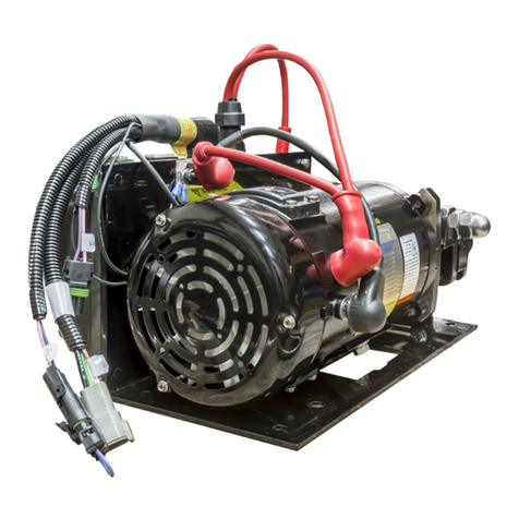
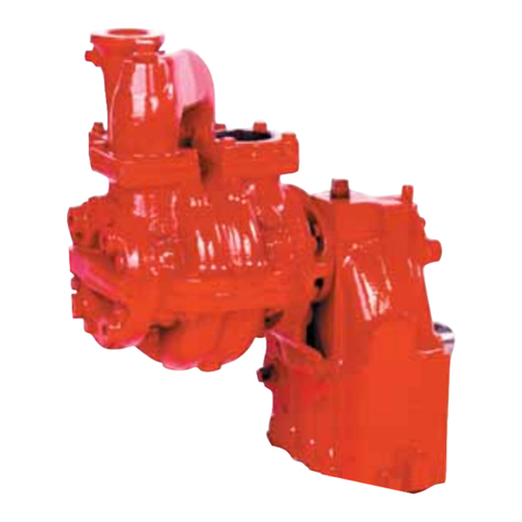
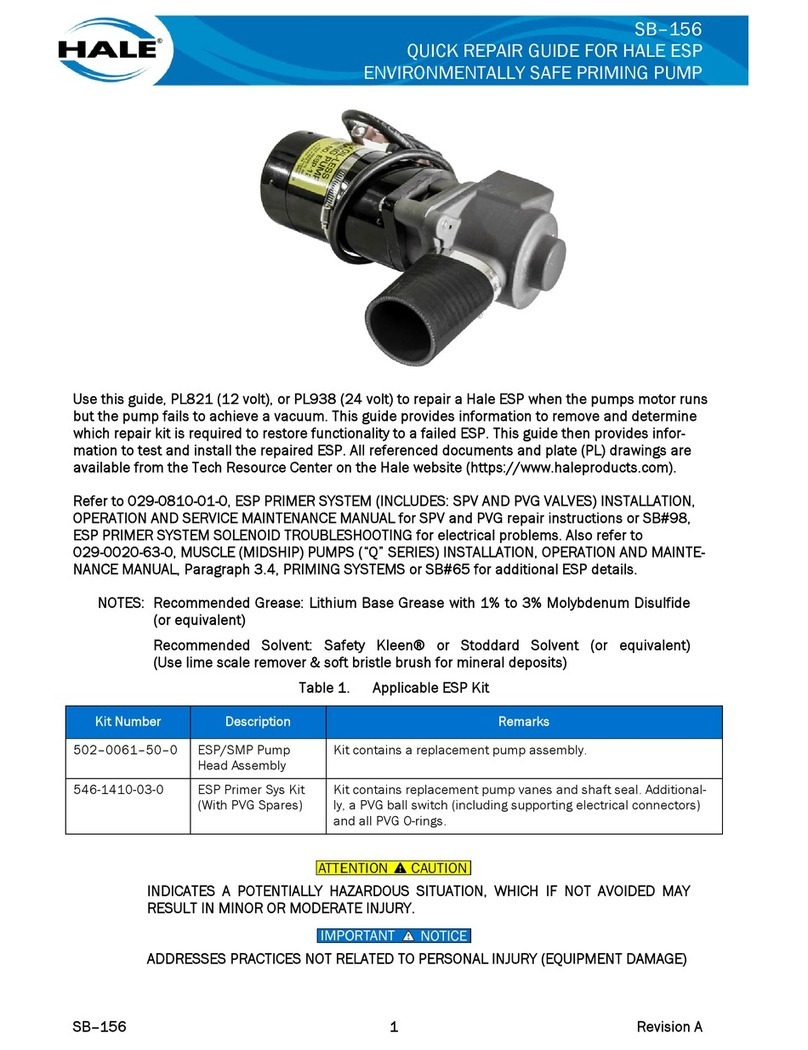
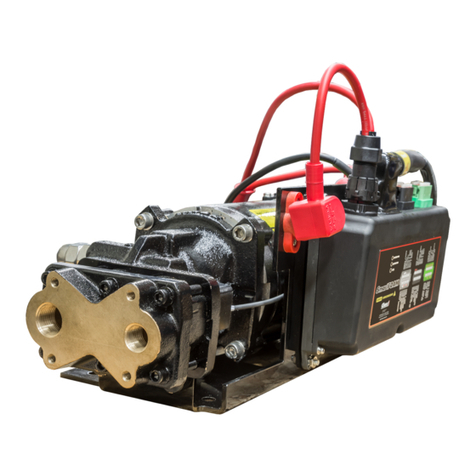
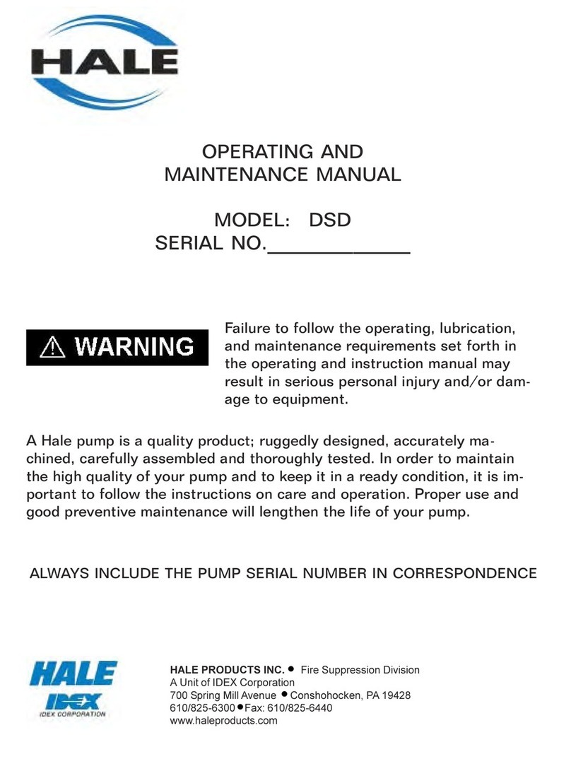
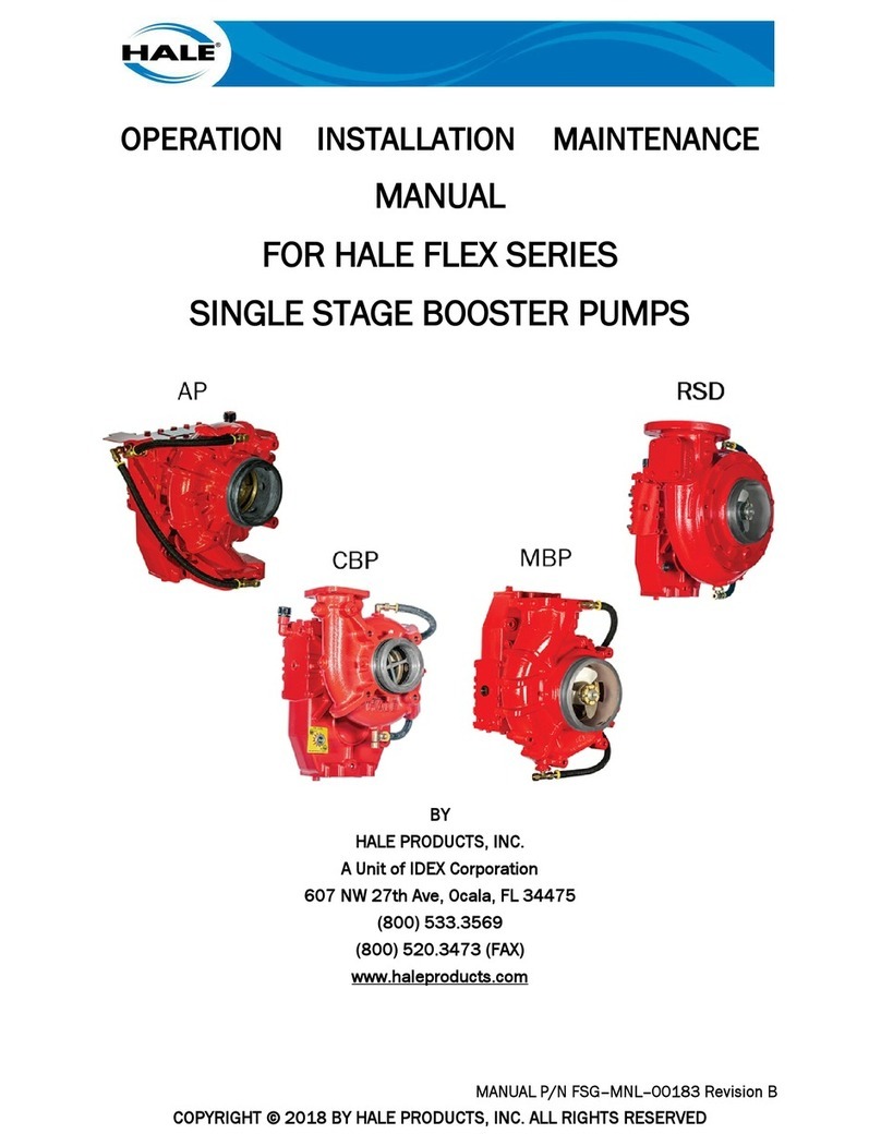
HALE Idex Godiva GP10/10 User manual

GP10/10
PORTABLE FIRE PUMP
OPERATING MANUAL
HALE PRODUCTS EUROPE LTD
Charles Street
Warwick CV34 5LR
ENGLAND
Tel: +44 (0)1926 623600 Fax: +44 (0)1926 623666
admin_haleuk@idexcorp.com www.haleeurope.com
GP/078/94
ISSUE 2 JANUARY 2005


i
PORTABLE PUMPS
SAFETY-RELEVANT DATA
Thank you for purchasing a Godiva Pump.
Godiva Portable Pumps are designed to give safe and reliable service – however, BEFORE
operation it is essential that the Operating Instructions are carefully read and understood.
A risk-assessment of the pump has been conducted with the following results:
MAINTENANCE
It is the responsibility of the user to ensure that the equipment is maintained in a safe operational
condition, as per regulation 5 in the Provision and Use of Work Equipment Regulations 1998.
TRAINING
It is essential that Godiva pumps are operated ONLY by TRAINED PERSONNEL. Manufacturer’s
training can be obtained on application to Hale Products Europe Ltd., Charles Street, Warwick
CV34 5LR, England. Tel: +44 (0)1926 623600.
ENGINE
When using Godiva pumps driven by a gasoline-powered engine, the following safety points
MUST be observed:
•DO NOT OPERATE the unit close to flammable materials or structures.
•Keep ALL UNTRAINED people AWAY from the unit during operation.
•PETROL is extremely flammable and MUST be HANDLED WITH CARE.
•DO NOT REFUEL until the engine is cold.
•DO NOT OVERFILL the fuel tank. After refuelling ENSURE that the fuel cap is refitted.
•DO NOT refuel whilst smoking or allow sparks or flames into the refuelling area.
•Be careful NOT TO SPILL fuel; if any fuel is spilled, ensure that the area is dry BEFORE
starting the engine. Godiva recommend refuelling when the engine is cold.
•DO NOT run the engine in an enclosed area as poisonous gases are given off which can cause
injury.
•The exhaust system becomes VERY HOT during operation and REMAINS HOT for a time
AFTER the engine has been stopped. DO NOT TOUCH the exhaust whilst the engine is hot.
•The starting system is driven by battery. Always connect the battery positive (+ve) cable
BEFORE the negative (–ve) and disconnect the negative BEFORE the positive.
•Batteries produce EXPLOSIVE GASES so keep sparks, flames and cigarettes away.
NOISE
When running, the engine-driven portable pump is noisy so EAR PROTECTION IS NECESSARY.
MANUAL HANDLING
The Godiva Portable Pump design incorporates suitable lifting handles or points.
A manual-handling sheet is provided with each model.
The secondary starting method (hand-start) provided MUST BE USED WITH CARE. Follow the
operating instructions provided.
S. Tudor
Engineering Manager
February 2001

ii
NOTES
The FULL Pump Serial Number must be quoted on ALL communications.
1) COOLING: IT IS VERY IMPORTANT THAT A MINIMUM DIFFERENTIAL
PRESSURE OF 3 BAR IS MAINTAINED IN THE PUMP UNIT TO ENSURE THAT
SUFFICIENT PUMPED WATER IS BEING CIRCULATED THROUGH THE HEAT
EXCHANGER TO PREVENT OVERHEATING OF THE ENGINE UNIT.
2) DRY RUNNING: This pump may only be run in a dry condition during the priming procedure,
i.e. typically 30 seconds at approximately 5,200 r.p.m.
Warning: Care should be taken if exceeding these figures as terminal damage may occur
to the gland-seal components if water is not present in the pump casing to both
cool and lubricate these components.
3) ACCIDENTAL STARTING – PREVENTION
a) While work is being carried out on the engine, pump or electrical Systems, disconnect the
battery cables – See b) below, and the spark-plug leads.
b) When working on the HONDA engine, make sure that BOTH the BATTERY and PULSER
ROTOR connections are disconnected. Battery disconnection alone DOES NOT ensure the
prevention of accidental engine starting as movement of the rotor will trigger the ignition. The
pulser-rotor connections are located under the Capacitor Discharge Ignition (CDI) cover on the
R.H. – side of the engine.
GENERAL
The terms “L.H.” (Left-hand) and “R.H.” (Right-hand) used in this book apply when the pump unit
is viewed from the suction tube-end.
ACKNOWLEDGEMENT
We acknowledge with thanks the permission given by the HONDA MOTOR CO. LTD., to
reproduce material from that company’s engine publications as necessary.
ASSOCIATED PUBLICATIONS
Publication Part Number
Spare Parts Manual ........................................................................................................ GP/080/94
Workshop Manual ......................................................................................................... GP/078/94
The Company reserves the right to change details of equipment and product specifications without prior notice as part
of its policy of continuous development. © Copyright Godiva Limited 1994 Printed in England

iii
CONTENTS
Page
GENERAL DATA............................................................................................................................ 1
ENVIRONMENTAL PROTECTION .............................................................................................. 2
HEALTH AND SAFETY................................................................................................................. 2
RECOMMENDED LUBRICANTS, FUEL AND ANTI-FREEZE ................................................. 4
DESCRIPTION................................................................................................................................. 5
PREPARING THE PUMP UNIT FOR RUNNING......................................................................... 9
STARTING THE ENGINE – Inc. Manual Back-up Starting......................................................... 11
RUNNING THE ENGINE.............................................................................................................. 12
PRIMING THE PUMP FROM OPEN WATER ............................................................................ 12
HYDRANT PUMPING .................................................................................................................. 13
PROTECTION AGAINST FROST................................................................................................ 14
MAINTENANCE............................................................................................................................ 15
MONTHLY PUMP TEST .............................................................................................................. 17
ENGINE FAULT TRACING ......................................................................................................... 18
PUMP FAULT TRACING ............................................................................................................. 22

iv

1
GENERAL DATA
ENGINE DATA
Engine ................................................................... Honda BF45A (Modified)
Configuration ....................................................... 3-cylinder 4-stroke, OHC vertical crankshaft
Bore and Stroke .................................................... 70 mm x 70 mm
Capacity ................................................................ 808cc (49.4 cu.in.)
Rated Power ......................................................... 6600 r.p.m. max.*
Idle Speed ............................................................. 950+/–50 r.p.m.
Valve Clearance – Inlet (COLD) ......................... 0.13 – 0.17 mm
– Exhaust (COLD) .................... 0.21 – 0.25 mm
Battery (Low-Maintenance) ................................. 12 Volt 18 Amp Hr, Neg. Earth
Ignition Timing Range ......................................... 5° – 32° BTDC
Spark Plug – Type ................................................ N.G.K. D7EA or equivalent
– Gap ................................................. 0.6 – 0.7mm
Fuel Tank Capacity .............................................. 14 litres
Fuel Pump ............................................................ Diaphragm-type driven from camshaft.
Carburettors (Three) ............................................. Constant-vacuum type
Lubrication System .............................................. Pressure-feed and splash
Oil Sump Capacity (With Filter) .......................... 2.6 litres
(Without Filter) .................... 2.0 litres
Oil Pressure (Engine at 80°C) .............................. 1.5 bar at 950+/–50 r.p.m.
Oil Filter ............................................................... Honda screw-on disposable cartridge
Cooling System .................................................... Water circulation by engine pump with
thermostat, heat exchanger, oil cooler and
header tank.
Cooling Water Capacity ....................................... 5.0 litres
Operating Temperature ........................................ 72°C
Anti-Freeze ........................................................... Ethylene Glycol-base
Starter – Electric ................................................... Electric starter 0.9kw (Inertia-type)
– Manual ................................................... Rope-wrap on flywheel
* Full throttle r.p.m.
PUMP DATA
Pump – Model ...................................................... GPl0/l0
– Type ........................................................ Single-stage, centrifugal.
Rated Output ........................................................ 1,000 litres at 10 bar and 3 m lift.
Pump Shaft Seal ................................................... Spring-loaded, self-adjusting, carbon-faced
gland with silicon-carbide counterface.
Delivery Valves .................................................... Screw-down DIN-type (2-OFF).
Priming ................................................................. Exhaust-gas ejector and automatic priming
valve.
Thermal Relief Valve (Optional)
Operating Temperature .......................... 42°C
Length (Cradle Handles Closed) .......................... 680 mm
Width .................................................................... 495 mm
Height (Complete Unit) ........................................ 605 mm
Weight (With Battery, Oil Coolant and Fuel) ...... 112 kg
2
ENVIRONMENTAL PROTECTION
It is ILLEGAL to pour engine oil and other contaminants on to the ground, down sewers and drains
or into water courses.
Disposal of these MUST be made through AUTHORISED waste-disposal contractors to licensed
waste disposal sites.
IF IN DOUBT contact the Local Authority for advice on disposal facilities.
HEALTH AND SAFETY
To avoid injury, Godiva recommends that operators should take ALL necessary precautions to
safeguard themselves and others and to follow the operating procedures laid down in this book.
When handling gasoline, batteries or hot machinery:
a) DO NOT SMOKE.
b) DO NOT EXPOSE volatile fluids or battery gases to a naked flame.
c) DO NOT TOUCH hot parts of machinery.
d) AVOID PROLONGED SKIN CONTACT with fluids, especially if they are known to be, or
are suspected of being, either corrosive or carcinogenic.
e) PROTECT THE EYES as necessary.
f) DISCONNECT THE BATTERY when working on the electrical system to avoid short-circuits.
g) DO NOT LIFT heavy weights without suitable assistance.
h) DO NOT INHALE fumes or gases.
i) DO NOT REMOVE protective guards or shields.
j) DO NOT SPILL fuel when refuelling – fuel vapour or spilt fuel can easily be ignited.
k) CLEAN UP IMMEDIATELY any spilt fuel, oil or anti-freeze.
1) WASH YOUR HANDS IMMEDIATELY after handling fuel, oil or anti-freeze.
Further useful information regarding Health and Safety and the GP10/10 Portable Fire Pump is
illustrated on the following page.
Gauges
Do not clean the glass surfaces of the gauges with abrasive or solvent cleaners. These will cloud the
glass surface, use a mild detergent and water.

3
DRY WET CONSTRUCTION MATERIALS
WEIGHT Kg 94 112 PUMP CASING ALUM.
CENTRE OF
GRAVITY
mm
X 354.0 367.0 IMPELLER ALUM.
Y 237.0 225.0 PUMP SHAFT ST.STL
Z 318.0 316.0 WEARING RINGS FIBRE
LIFTING
FORCES
Kg
P1 21.5 26.5 MANIFOLD ALUM.
P2 24.5 28.5 CRADLE ST.STL
P3 25.5 29.5 ENGINE HEAD ALUM.
P4 22.5 27.5 BLOCK ALUM.
NOTE! THE WET WEIGHT IS INCLUSIVE OF THE FULL CAPACITY OF
ENGINE OIL, COOLING WATER, AND FUEL
GP10/10 Portable Fire Pump – General Information
GODIVA RECOMMENDS
TEAM LIFTING TO BE
ADOPTED IF NO OTHER
FORM OF LIFTING IS
AVAILABLE. USE OF THE
LIFTING FACILITIES THAT
ARE PROVIDED ON THE
UNIT IS STRONGLY
ADVISED.

4
RECOMMENDED
LUBRICANTS, FUEL AND ANTI-FREEZE
ENGINE LUBRICANTS
STANDARD AMBIENT TEMPERATURE LUBRICANT VISCOSITY
SF/CC, CD –20°C (–5°F) and above 10W/40
GASOLINE FUEL
Premium Grade Gasoline
with Minimum Research Octane Number of 86 (Unleaded*).
*NOTE: The pump can be run on 4-star fuel but not for sustained periods as damage to exhaust
valves and seats can result. Godiva therefore cannot accept responsibility for any claims resulting
from sustained use of leaded fuel in this pump.
BATTERY
Fill the battery with accumulator sulphuric acid (electrolyte) of specific gravity 1.277 up to the
upper acid level mark. Battery and acid should have a temperature of at least 10°C. In order to
immediately achieve full battery performance, it is recommended to charge the battery briefly after
filling with acid. Check the acid level after charging, and if necessary correct with more acid.
Distilled water should not be used for the initial filling of the battery, but can be used for
subsequent topping up.
ANTI-FREEZE
Ethylene-Glycol base type

5
DESCRIPTION
PUMP
The Godiva GPl0/l0 Model is a single-stage, centrifugal pump powered by a’ Honda engine:
The pump suction tube, volute, discharge valves, manifold and impeller are all manufactured from
corrosion-resisting aluminium alloy, while the pump shaft is of stainless steel.
The impeller is hydraulically-balanced to reduce end-thrust and pumpshaft-sealing is accomplished
by a spring-loaded, self-adjusting, carbon-faced gland running against a silicon-carbon counterface.
Optional extras for the GPl0/l0 Pump are as follows:
1) TRV42 Thermal Relief Valve.
2) Floodlight assembly.
3) Remote Fuel Tank and Hose Assembly – 23.7-litre capacity.
4) Wheelbarrow Assembly
5) Axle & 2 Wheel Assembly
ENGINE
The modified Honda engine is an in-line, vertical crankshaft, 3-cylinder, 4-stroke unit with a belt-
driven overhead camshaft and triple constant-vacuum carburettors.
Engine capacity is 808cc with 70mm bore and stroke.
The aluminium cylinder block, incorporating the crankcase, is fitted with cast-iron cylinder liners
and a robust crankshaft is supported on four main bearings.
Aluminium pistons are used and the cylinder head is of heat-treated aluminium.
The electronic ignition system provides excellent starting characteristics and eliminates the need for
any maintenance.
An electronic overspeed-and-engine protection system is also fitted. This actuates in the event of
high coolant temperature or low oil pressure by progressively reducing the engine speed to
2,800 r.p.m. until the problem is solved, then returning gradually to the set speed.

6
INSTRUMENTS AND CONTROLS
Switches, gauges and controls fitted (See Fig. 1):
Compound Gauge (1) ........................ Indicates vacuum in pump suction tube during priming.
Pressure Gauge (2) ............................. Indicates pump unit water pressure.
Throttle Control (3) ............................ Controls engine speed.
START Button (4) ............................. Press – until engine starts.
Ignition Switch (5) ............................. Toggle to LEFT for ignition ON.
Toggle to RIGHT to switch OFF and to STOP the engine.
Choke Control (6) .............................. Operation: FULLY OUT – Cold Engine Start
MIDWAY – Warm-up
FULLY IN – Choke Inoperative
Hours Meter (7) ................................. Indicates TOTAL hours engine running time.
Coolant Temperature Lamp (8) ......... Indicates high engine coolant temperature.
Oil Pressure Lamp (9) ........................ Indicates low engine oil pressure.
Panel Lamps (10) ............................... Provides instrument panel and gauges illumination when
ignition switch is in ‘ON’ position.
Primer Rod Control (11) .................... Pulling the control rod activates the pump priming system.
Lighting Socket (12) .......................... Provides a power source for the optional flood light or for
battery charging.
Fig. 1 Instruments, Gauges and Controls

7
COOLING SYSTEM
To enable normal operating temperatures to be maintained over extended running periods, a closed-
circuit engine-cooling system is used.
The system incorporates a heat exchanger, oil-cooler and header tank.
Raw water is piped down from the volute through a strainer to the engine oil cooler, then on
through the heat-exchanger tubes and returned to the suction tube.
The closed-circuit engine-cooling system takes coolant from the engine which is then passed
through the heat exchanger where it comes into contact with the internal tubes containing the
pumped raw water.
Note: The raw water and engine coolant do not come into direct contact but the heat transfer
takes place through the walls of the internal tubes.
The coolant then passes through the coolant header tank and is returned to the engine water pump.
IMPORTANT NOTE:
It is VERY IMPORTANT that a DIFFERENTIAL PRESSURE OF 3 BAR is maintained in the
pump unit to ensure that the pumped water is being circulated through the heat exchanger to prevent
overheating of the engine unit.
Fig. 2 Water and Coolant Circuit

8
DELIVERY VALVES
Screw-Down DIN-Type
By turning the handwheel counter-clockwise, the valve can be opened for the discharge of water.
When the valve is open and no water is being discharged, the valve seal is held against the volute
discharge port by a spring in the valve body.
When the pump is priming, the valve seal acts as a non-return valve so that the prime is not lost.
The release knob allows the valve seal to be lifted higher than normal through the action of the
handwheel being turned with the release knob pulled out.
Note: This operation is only carried out after the pump has been STOPPED.
This operation will allow the valve seal to be raised above the discharge port and enable water to
drain past the valve from hoses and dry-risers.
PRIMING
An exhaust gas ejector-type priming system is fitted incorporating an automatic priming valve.
The priming system is activated by pulling the primer control rod to the limit of its travel with the
engine throttle approximately 3/4 open.
When priming is complete, the control rod is released and returns to its normal position under the
influence of a return spring.
Discharge of water is then controlled by the position of the engine throttle control and delivery-
valve opening.
FLOODLIGHT UNIT (Optional)
The floodlight is located adjacent to the engine valve cover.
It may be raised to a height of 1,200mm measured from floor level, rotated through 360° and the
actual lamp unit tilted through 90°.
The power-supply cable for the lamp plugs into a socket on the instrument panel.
The socket may also be used for battery-charging purposes.

9
PREPARING THE PUMP UNIT FOR RUNNING
Check the following points BEFORE starting the engine:
COOLING SYSTEM
The heat exchanger and header tank are mounted at the R.H-side of the engine.
Unscrew the filler cap of the header tank and, if necessary, add CLEAN water until the level is
approximately 20mm below the bottom of the filler neck.
Use soft rainwater – if available – NEVER use dirty or contaminated water.
Use only anti-freeze suitable for aluminium engines and mix with water in the correct ratio * for the
prevailing or expected minimum temperature. (See PROTECTION AGAINST FROST).
A compartment is incorporated in the header tank for the storage of the rope which can be used for
manual back-up starting. (See STARTING THE ENGINE – Manual Back-Up Starting).
* Anti-freeze MUST be mixed in the proportions stated for the particular brand recommended.
ENGINE LUBRICATING OIL
The lubrication oil filler is positioned at the top of the engine valve cover.
Check the oil level every 5-HOURS RUNNING TIME or EVERY TIME that the unit is used.
The oil dipstick is positioned on top of the engine oil sump at the L.H.-side of the engine.
To check the oil level proceed as follows:
IMPORTANT: BEFORE checking the oil level with the dipstick – ENSURE that the engine is
SWITCHED OFF and that the unit is LEVEL
Note: THE OIL LEVEL CANNOT BE CHECKED WHILE THE ENGINE IS RUNNING.
Always allow the engine to stand for a few minutes after switching off so that the oil remaining
around the engine may return to the sump.
Withdraw the dipstick, wipe clean, re-insert it and then withdraw it again to check the oil-level
reading.
If the oil level is NOT up to the TOP mark of the dipstick, add fresh oil to the correct level.
(See list of RECOMMENDED LUBRICANTS).
IMPORTANT: NEVER ALLOW THE LEVEL TO FALL BELOW THE BOTTOM MARK ON
THE DIPSTICK.
Note: Do not over-fill when topping-up. Engine-sump capacity is 2.6 litres (inc. filter).

10
FUEL TANK
The fuel tank is mounted at the L.H.-side of the unit with a capacity of 14 litres.
Check that a sufficient quantity of fuel is present for the anticipated requirements.
No fuel tap is fitted due to the position of the fuel tank. Fuel is drawn from the tank by the engine
fuel pump when the engine is running.
The fuel-level gauge is incorporated in the screw-on filler cap.
IMPORTANT: DO NOT USE LEADED FUEL – The ignition timing is set for the use of
UNLEADED GASOLINE.
Note: The fuel tank is connected to the engine via a quick-release connector which can be
unfastened to allow an external tank to be connected.
THERMAL RELIEF VALVE (Optional)
The raw-water pump system can incorporate a TRV42 Thermal Relief Valve.
Should the pump-water temperature exceed 42°C, the valve releases water via a transfer pipe into
the silencer. The resultant excess vapour (steam) produced provides a visual indication of excess
pump-water temperature. Alternatively the pipework may be modified to discharge the water to the
ground.
Note: This situation can occur if the pump is left running for excessive periods of time with the
hose-nozzle controls or the discharge valves in the closed position.

11
STARTING THE ENGINE
First, check the fuel, oil and water levels (See under PREPARING THE PUMP UNIT FOR
RUNNING). Then pull the choke control FULLY OUT (Cold-Starting Position) – See Fig. 3.
POSITION STATUS
– FULLY OUT – COLD START
– MIDWAY – WARMING UP
– IN – NORMAL RUNNING
Fig. 3. Choke-control Positions
Open the throttle slightly.
Switch on the ignition by pushing the ignition-switch toggle to the LEFT.
To start the engine press the starter button on the control panel and release it as soon as the engine
starts. The oil pressure light should extinguish immediately - if it does not: stop the engine and
investigate the reason.
Note: When restarting a HOT engine, DO NOT USE the choke control – to do so may prevent
the engine from starting.
IMPORTANT: DO NOT allow the pump to run in a DRY condition, except during the normal
priming procedure.
Manual Back-up Starting
A compartment, integral with the coolant tank, is provided for the storage of the starter rope for
emergency starting.
Release the flexible tab handle securing the flywheel cover and hinge back the cover to reveal the
flywheel.
Unscrew the RED cap and withdraw the rope from the storage compartment. Ensure that the
ignition switch is in the OFF position to prevent accidental starting.
Insert the knot of the rope into one of the cutaways in the periphery of the flywheel and wrap the
remainder of the rope counter-clockwise around the flywheel in the groove provided.
Switch ON the ignition and open the throttle slightly.
Give the rope a sharp, but continuous pull to start the engine.
Return the cover to its closed position and secure it with the flexible tab handle.

12
WARNING: TAKE EXTREME CARE TO KEEP CLEAR OF THE ROTATING
MACHINERY WHEN THE ENGINE STARTS.
Always replace the rope in the compartment provided and then refit the cap.
RUNNING THE ENGINE
If the engine is started with the intention of running it only for a short period, it is important that it
reaches its normal operating temperature before being switched off.
This is to allow the corrosive condensate, generated during normal running of the engine and
evaporating as the engine warms up, to be expelled from the system. These corrosive deposits if left
in the system will cause deterioration of engine parts.
IMPORTANT: DO NOT allow the pump to be run DRY during the above procedure.
PRIMING THE PUMP FROM OPEN WATER
Set the pump approximately level – if necessary, use packing under the frame.
Remove the suction cap, connect the suction hose and close the delivery valves.
Ensure that the connection is tight and that the end of the suction hose, with strainer attached, is
submerged to a sufficient depth below the level of the water supply.
If the suction hose-end is too near to the surface of the water supply, a vortex may form.
Conversely, if the end of the suction tube is on the bottom (or even too near the bottom) then sand
or gravel for example, may be drawn into the pump. In this situation, a basket filter should also be
used.
We recommend that the use of those pumping positions resulting in any part of the suction hose
being higher than the pump-suction connection are avoided – to prevent air pockets in the suction
hose.

13
Priming
Pump priming is accomplished using the following method:
1) Start the engine and open the throttle approximately 3/4 of its travel.
2) Pull the primer operating rod out to its limit - there is no need to use excessive force.
3) Move the throttle-setting to give maximum smooth running and watch the gauges.
4) At the first positive ‘flick’ of the pressure gauge, release the primer rod.
5) Partially-open a delivery valve to release trapped air and ease back the throttle.
6) Fully-open the delivery valve(s) by turning the handwheel(s) counter-clockwise.
The pump will now be discharging water - pressure should be regulated by opening and closing the
discharge nozzles and throttle as required.
Note: When pumping, GRADUALLY make adjustments to the engine speed - NEVER suddenly
jerk the throttle either open or closed.
HYDRANT PUMPING
Remove the suction cap.
Connect the pump with a hydrant-to-suction adaptor.
Fully-open the delivery valves.
Start the engine and set the throttle control so that the engine is idling.
Turn on the hydrant.
Open the throttle only so far as is necessary to maintain the desired working pressure.
Note: The compound gauge needle MUST NOT be allowed to drop below zero, otherwise a
vacuum will be created on the suction-side of the pump causing damage to the mains water
supply or the collapse of the supply hose.

14
PROTECTION AGAINST FROST
As a precautionary measure when frost is first anticipated, drain the pump-volute casing by tipping
the whole unit towards the suction-end, or remove the drain plug situated at the base of the volute
casing. Then open the drain valve located on the volute.
Use an anti-freeze solution in the engine coolant system in the correct proportions stated for the
particular brand recommended.
As the engine is constructed of aluminium alloy, it is essential that the anti-freeze solution is of the
type suitable for use with this material.
If no anti-freeze is available, it will be necessary to drain the engine.
Always drain the cooling system while the engine is WARM.
IMPORTANT: NEVER attempt to run the engine without water.
Note: After draining, attach a ‘WATER DRAINED’ notice to warn others that the system must
be refilled before restarting the engine.
Table of contents
Other HALE Water Pump manuals

HALE
HALE FoamLogix 3.3 User manual

HALE
HALE Silencer APS Series Installation and user guide

HALE
HALE Godiva KP1 User manual

HALE
HALE HALE FLEX Series Instruction Manual

HALE
HALE SB-156 Operator's manual

HALE
HALE SUPERCHIEF User manual

HALE
HALE SAM User manual

HALE
HALE FYR-PAK Installation and operating instructions

HALE
HALE FOAM MASTER 3.3 Operating and installation instructions

HALE
HALE AP User manual
Popular Water Pump manuals by other brands

Eaton
Eaton 70523 Parts and Repair Information

Graco
Graco ChemSafe 205 Instructions - parts

Graco
Graco 29:1 Lube Pro instructions

Cane
Cane Crono user guide

GORMAN-RUPP PUMPS
GORMAN-RUPP PUMPS T SERIES Installation, operation, and maintenance manual with parts list

CAT Pumps
CAT Pumps 3570 Series Service manual