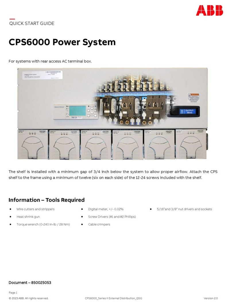
ABB CPS6000-Systems-48V DC Power User manual

Page 1
© 2021 ABB. All rights reserved. CP:S6000_External Distribution_IG Rev. 1.3
INSTALLATION GUIDE
CPS6000-Systems (-48V DC Power)
Installation Manual
19 and 23-Inch Systems
Product Manual: CC848879683
Issue 2 March 2010

Page 2
© 2021 ABB. All rights reserved. CP:S6000_External Distribution_IG Rev. 1.3
This page is intentionally left blank.

Page 3
© 2021 ABB. All rights reserved. CP:S6000_External Distribution_IG Rev. 1.3
Table of Contents
Customer Service Contacts ·········································································································· 4
1. Safety Statements························································································································· 5
2. Product Specification···················································································································· 9
3. Installation ··································································································································· 13
Unpacking and Safety Precautions······································································································ 13
Installation Tools ···································································································································· 13
Torque Settings ······································································································································ 13
Frame Mounting······································································································································ 13
DC Reference (CO) Ground and Chassis Ground··············································································· 14
Battery String and DC Load Connections····························································································17
Battery Monitoring Connections·········································································································· 23
Local Port (RS-232 / USB) Connection ································································································26
Rectifier Installation·······························································································································28
4. Initial Start-up······························································································································ 29
Minimum Controller Configuration ·····································································································29
5. Troubleshooting ·························································································································· 33
Rectifier Alarms······································································································································· 33
Troubleshooting Chart ··························································································································34
6. Product Warranty ························································································································ 37
Appendix A: Pulsar Controller··········································································································· 39
User Interface Overview ························································································································39
Menu Navigation Buttons······················································································································40
System Status Display ···························································································································40
Appendix B: Pulsar Wiring Connector Definitions ··········································································49
7. Revision ·········································································································································· 53
PRODUCT MANUAL
CPS6000-Systems (-48V DC Power)
Installation Manual

Page 4
© 2021 ABB. All rights reserved. CP:S6000_External Distribution_IG Rev. 1.3
Customer Service Contacts
For customers in the United States, Canada, Puerto Rico, and the US Virgin Islands, call
1- 800-THE-1PWR (1-877-546-3243). This number is staffed from 7:00 am to 5:00 pm Central Time (zone
6), Monday through Friday, on normal business days. At other times this number contacts an
answering service with on-call personnel for out of service emergencies.
Customer Training
ABB Power offers customer training on many Power Systems products. For information call
1-972-244-9288. This number is answered from 8:00 a.m. until 4:30 p.m., Central Time Zone (Zone 6),
Monday through Friday.
Downloads and Software
To download the latest product information, product software and software upgrades, visit our web
site at abbpowerconversion.com

Page 5
© 2021 ABB. All rights reserved. CP:S6000_External Distribution_IG Rev. 1.3
1. Safety Statements
CPS6000 DC Power System accepts operating AC voltage between 85V and 275V, 47-63 Hz, and
produces a regulated DC Output of 42-58V. It delivers a maximum DC output of 600A at an operating
temperature range of -40C to +50C. Some rectifiers are derated from 50C to 75C (2% per degree C).
HAZARDOUS VOLTAGE AND ENERGY LEVELS CAN PRODUCE SERIOUS SHOCKS AND BURNS. This
power system and connected cables will have hazardous energy and voltages present. Follow all
safety warnings and practices when servicing this equipment. This equipment must be installed,
serviced, and operated only by authorized, qualified and trained personnel who have the necessary
knowledge and practical experience with electrical equipment and who understand the hazards that
can arise when working on this type of equipment. Observe all local and national electrical,
environmental and workplace codes.
APPROVALS
• System: Underwriters Laboratories (cUR) Recognized per the U.S. and Canadian (Bi-National) Standard for Safety
of Information Technology Equipment, Part 1: General Requirements, CAN/CSA C22.2 No. 60950-1-03, UL 60950-1,
1ST Edition. Considerations were also given to the safety requirements of IEC 61204-7, First Edition, Low voltage
power supplies, d.c. output, Annex PS-E.
• Rectifiers: Underwriters Laboratories (cUR) Recognized per the U.S. and Canadian (Bi-National) Standard for
Safety of Information Technology Equipment, Part 1: General Requirements, CAN/CSA C22.2 No. 60950-1-03, UL
60950-1, 1ST Edition or evaluated to EN60950-1 by an EC Notified Body, as appropriate. The CE Mark
demonstrates compliance with the European Union Council Directives for Low Voltage and EMC.
INSTALLATION SITE
• Install only in restricted access areas (dedicated equipment rooms, equipment closets, or the like) in accordance
with paragraphs 110.18, 110.26, and 110.27 of the U.S. National Electric Code (NEC), NFPA 70, and pursuant to
applicable local codes.
• This equipment is to be used in controlled environments (an area where the humidity is maintained at levels that
cannot cause condensation on the equipment, the contaminating dust is controlled, and the steady-state
ambient temperature is within the range specified). This equipment must not be installed over combustible
surfaces.
• CPS6000 is suitable for connection to ac utility systems where the expected level of lightning surges complies
with ANSI C62.41 Category B or IEC 60664-1 Overvoltage Category II.
• A service entrance surge protector is required in applications where the installation categories cannot be
classified as being compliant to either ANSI C62.41 Category B or IEC 60664-1 Overvoltage Category II.
• CPS6000 rectifiers have been tested for repeated lightning surges typically found in an Overvoltage Category III
installation; however, a service entrance surge protector is recommended in cabinet applications to bring the
power feeds in compliance to the installation categories above. The service entrance protection should be
coordinated with the protection provided in the power modules.
• The power module provides common-mode protection via a 320V MOV in series with a 2500V gas-discharge
device and differential-mode protection via a 320V MOV in series with a 3.5A fuse.

Page 6
© 2021 ABB. All rights reserved. CP:S6000_External Distribution_IG Rev. 1.3
AC
• An accessible ac disconnect/protection device to remove ac power from the equipment in the event of an
emergency must be provided.
• AC branch circuits to this equipment must be protected with either fuses or circuit breakers sized as required by
the National Electric Code (NEC) and/or local codes. The maximum size of the over-current protector is based on
the rectifier type used. Refer to Table 1 for appropriate breaker to assure rating of equipment will not exceed 80%
of the value of the protector chosen.
• The equipment could be powered by multiple ac inputs. Ensure that the appropriate circuit protection device for
each ac input being serviced is disconnected before servicing the equipment. Do not disconnect permanent
bonding provisions unless all ac inputs are disconnected.
• High leakage currents are possible due to contribution from multiple AC input connections. Earth ground
connection is essential before connecting the ac source to the shelf. This connection must be achieved by
ensuring that the shelf is properly grounded as shown in the Installation Section.
• In enclosed equipment cabinets, the mounting framework must be connected directly to the cabinet ac service
ground bus. For applications in huts, vaults, and central offices, the framework must be connected to the system
integrated ground grid.
• CPS6000 outputs are not connected to earth. Earthing of rectifier outputs may be performed externally to the
shelf at a “ground window” or “mesh ground”. Reliable earthing of the DC return bus (DC reference Ground) and
the chassis ground should be performed.
WIRING
• For installations in the United States, Listed compression connectors shall be used to terminate field-wired
conductors, where required. For all installations, the appropriate connector is to be applied only to the correct
size conductor as specified by the connector manufacturer, using only the connector manufacturer's
recommended tooling or tooling approved for that connector.
• If the proper connector for the country of installation is not provided, obtain appropriate connectors and follow
manufacturer’s and all local requirements for proper connections. All national and local rules and regulations
should be followed when making field connections.
• Insulation on field-wired conductors should be rated no less than 90° Celsius. Wire conductor size should be sized
per electrical codes for 75° Celsius wire, and based on the ampacity of the associated protection device.
• Battery input cables must be dressed to avoid damage to the conductors (caused by routing around sharp edges
or routing in areas where wires could get pinched) and undue stress on the connectors.
• Alarm contacts on the office alarm connector are not fused in the controller; therefore, current limiting protection
for these contacts must be provided by external circuits. Maximum ratings for alarm connections are 60Vdc and
0.5 amperes. Exceeding these maximum ratings could result in fire or damage to the unit.
• Torque electrical connections to the values specified on Table 2.
DC PROTECTORS
• The D.C. outputs up to 250A are available. The DC output discharge currents shall not exceed 80% of their circuit
breaker or fuse rating.
• Fuse and circuit breaker loads must not exceed 80% of the fuse and/or circuit breaker current rating.
• The short circuit current capability of the battery input to the distribution panel must not exceed 10,000A.
• Installing fuses or circuit breakers not specified for use in this shelf may result in injury to service personnel or
equipment damage.
• The telecom-type (e.g., GMT type) fuses can produce sparks during interruption or clearing of a fault on a high
energy circuit. Use only fuses provided with safety caps for this type of circuit. Installing telecom-type fuses not
equipped with safety caps may result in injury to service personnel.
Page 7
© 2021 ABB. All rights reserved. CP:S6000_External Distribution_IG Rev. 1.3
• While installing batteries, follow all safety precautions outlined in the appropriate battery product manuals.
• Batteries are connected in parallel with the output of the rectifiers. Turning off the rectifiers will not necessarily
remove power from the bus. Make sure the battery power is also disconnected and/or follow safety procedures
while working on any equipment that contains hazardous energy/voltage.

Page 8
© 2021 ABB. All rights reserved. CP:S6000_External Distribution_IG Rev. 1.3
This page intentionally left blank.

Page 9
© 2021 ABB. All rights reserved. CP:S6000_External Distribution_IG Rev. 1.3
2. Product Specification
CPS6000 is a -48V modular power system designed for 19-inch (483mm) or 23-inch (584mm)
mounting frames. These systems include 1 or 2 rectifier shelves and 1 or 2 distribution panels.
Rectifier shelves have either 4 slots or 6 slots providing up to 200A or 300A of DC power per shelf. AC
input options include AC cords or terminal blocks. The AC cord option is 10 gage cords with a L6-30P
plug each feeding two rectifier slots. Terminal block options are located either on the back of the
rectifier shelf or in a front accessible ac box as shown in the figure below.
The initial distribution panel includes the Pulsar controller mounted on the door and either 20 or 26
selectable distribution positions that can be configured as either battery inputs or load outputs.
Systems may be equipped with Low Voltage Battery Disconnect (LVBD), Low Voltage Load Disconnect
(LVLD) or no LVD. The supplemental distribution panel has 20 or 26 additional load positions.
Distribution panels are 7” (4U) high, rectifier shelves and the AC box are 3.5” (2U) high. The system
depth is 14”. The rear terminal block option adds an additional 3 inches of depth.
Figure 1: System shown with doors open

Page 10
© 2021 ABB. All rights reserved. CP:S6000_External Distribution_IG Rev. 1.3
Rectifier Specifications
The following constant-power, vertical airflow rectifiers are available for order with this system.
Values listed are per rectifier. Maximum Heat Dissipation numbers are calculated at 175VAC and
maximum DC voltage and current values for the rectifier.
Figure 2: Typical Rectifier Numbering
Model
Number of Rec-
tifier
Max DC
Current (Idc))
Nominal DC
Voltage (Vdc)
DC
Voltage (Vdc)
Range
AC Voltage (Vac)
Range
Nominal AC
Current (A) Max BTU/hr Max Watts
QS861A 15A 48 42-58 85-150 7.8 450 132
48 42-58 150-275 4.4 445 130
QS852A 20A 48 42-58 150-275 6454 133
QS853A 25A 48 42-58 150-275 7.4 724 212
QS862A 25/30A 48 42-58 85-150 12.0 604 177
48 42-58 150-275 8.8 724 212
QS864A 40A 48 42-58 150-275 11.8 819 240
QS865A 50A 48 42-58 150-275 14.5 911 267
Table 1: Rectifier Specifications

Page 11
© 2021 ABB. All rights reserved. CP:S6000_External Distribution_IG Rev. 1.3
DC Circuit
The following figures show the DC circuit description for the system. 19” systems have 20 bullet-style
distribution positions per panel. 23” systems have 26 bullet-style distribution positions per panel. The
positions in the initial distribution panel are selectable between either battery inputs or load outputs.
Figure 3 shows the option where all load positions are connected to the system through a low voltage
load disconnect (LVLD). Figure 4 shows the option where the battery positions are all connected to
the system through a low voltage battery disconnect (LVBD). Breaker sizes up to 250A, TPS fuses to
70A and GMT fuses to 12A are available bullet modules for this system. DC Connections are made with
double hole lugs on ¼-20 studs on 5/8” centers. The maximum tongue width for breaker connections
is 0.68”.
Figure 3: DC Distribution Circuit with LVLD
Figure 4: DC Distribution Circuit with LVBD or No LVD

Page 12
© 2021 ABB. All rights reserved. CP:S6000_External Distribution_IG Rev. 1.3
This page intentionally left blank.

Page 13
© 2021 ABB. All rights reserved. CP:S6000_External Distribution_IG Rev. 1.3
3. Installation
Unpacking and Safety Precautions
Before unpacking the DC power system, note any physical package damage that could indicate
potential damage to the contents. After removing the components from their boxes and packing
material, inspect for any shipping or other damage. Always consider personal safety. Remove all metal
jewelry before beginning the installation. Care should be taken during the installation process to
prevent exposure of the equipment to wire clippings. If possible, rectifiers should remain in their
shipping boxes until the shelf wiring is complete.
Installation Tools
• Wire cutters and strippers
• Digital meter, +/- 0.02%
• Heat shrink gun
• Screw Drivers (#1 and #2 Phillips)
• Torque wrench (0-240 in-lb / 28 Nm)
• Cable crimpers
• 5/16”, 7/16”, ½” and 3/8” nut drivers and sockets
Torque Settings
The following table lists the recommended torque settings for all mechanical and electrical
connections according to screw and nut size.
Frame Mounting
The CPS6000 system is designed for a standard 19-inch or 23-inch wide equipment racks. The system
should be installed with a minimum gap of 3/4 inch below the system to allow proper airflow. Attach
the system to the frame using a minimum of 12 (six on each side)
12-24 screws included with the shelf. Weights of the systems is shown in the following table.
Screw or Nut Size Torque
Nm In-lbs.
4-40
6-32 1.5 12
8-32 22
10-32 4.25 37
12-24 5.75 50
¼-20 7.5 65
5/16-18 15.3 135
3/8-16 27.1 240
Table 2: Torque Settings

Page 14
© 2021 ABB. All rights reserved. CP:S6000_External Distribution_IG Rev. 1.3
Systems Weights
19” 23”
1 Distribution/1 Rectifier Shelf 41 lbs 54 lbs
2 Distribution/1 Rectifier Shelf 59 lbs 77 lbs
1 Distribution/2 Rectifier Shelf 55 lbs 74 lbs
2 Distribution/2 Rectifier Shelf 74 lbs 97 lbs
DC Reference (CO) Ground and Chassis Ground
Use a 1/4” diameter double-hole lug on 5/8”center (Not provided) to ground the chassis as shown in
the figure below. Torque connection to 65 in-lbs. The DC reference ground is connected to the return
bus as shown below. Use a 3/8” diameter double-hole lug on 1” centers (Not provided).
Figure 5: DC Reference Ground and Chassis Ground Connections

Page 15
© 2021 ABB. All rights reserved. CP:S6000_External Distribution_IG Rev. 1.3
AC Input Connections: (3 options)
Line Cords on Rectifier Shelves (15feet long with L6-30P Plugs)
Terminal Blocks on back of Rectifier Shelf
AC Box has knockouts for ¾” or 1” conduit.
Two sets of conduit ground studs are located in the
box. These
¼”studs accept two-hole ground lugs on 5/8”
centers.
One, two or three rectifiers may be fed from a single ac
feed using jumpers between the blocks. Attach jumpers
as shown below. Torque screw to 10 in-lbs
Snap loose plastic divider.
Install strap to connect adjacent
blocks.
If feeding 3 positions, At-
tach wire to center block.

Page 16
© 2021 ABB. All rights reserved. CP:S6000_External Distribution_IG Rev. 1.3
AC connection is typically 1-inch conduit
per rectifier shelf connected on either
the left or right side.
Two sets of conduit ground studs are
located on either side of the box. These
¼”studs accept two-hole ground lugs on
¾” centers.
One, two or three rectifiers may be fed
from a single ac feed using jumpers be-
tween the blocks. Attach jumpers as
shown below. Torque screw to 10 in-lbs
AC feed per rectifier
(no jumpers)
AC per two rectifiers
(1 jumper per 2 blocks)
AC per three rectifiers
(2 jumpers between 3 blocks)
If feeding 3 positions, At-
tach wire to center block.
Terminal Blocks in 2U AC Box
L1 connections L2 connections

Page 17
© 2021 ABB. All rights reserved. CP:S6000_External Distribution_IG Rev. 1.3
Battery String and DC Load Connections
The system has up to 52 bullet-style distribution positions. All positions in the initial distribution
panel are selectable between either battery inputs or load outputs. If the system is equipped with a
low voltage load disconnect LVLD, then all load positions are connected to the system through the
LVLD. If the system is equipped with a low voltage battery disconnect LVBD, then all battery positions
are connected to the system through the LVBD. Breaker sizes up to 250A, TPS fuses to 70A and GMT
fuses to 12A are available bullet modules for this system. DC Connections are made with double hole
lugs on ¼-20 studs on 5/8” centers. The maximum tongue width for breaker connections is 0.68”.
Adapter buses are available for larger cables. Notice the color coding in the distribution. Bus bars with
brown labeling are returns. Bus Bar with blue labeling are -48V. Labels are provided to identify battery
verses load positions on the ID label on the front door. The initial distribution panel with the controller
is rated for 600A. The supplemental (upper) panel is rated for 300A. Load distribution in system
accordingly.
Note: Yellow handle or black handle Bullet-style circuit breakers can be mounted as load or battery
connectors.
Figure 6: Selectable DC Distribution
Number of Conduits
Conduit Size
Number of Rectifiers
per
ac feed
Min External
ac
Breaker
Wire Gage
Number of Wires
in
Conduit
1 per 4-slot rectifier shelf
¾ inch
20A 10
40A
1 per 6-slot rectifier shelf
1 inch
20A 10 13
40A
60A
Yellow handle circuit breakers Send alarm in manual off or trip position; mid-trip breakers
Black handle circuit breakers Send alarm only in tripped position
Table 3: AC Wire and Protectors for 50A rectifiers

Page 18
© 2021 ABB. All rights reserved. CP:S6000_External Distribution_IG Rev. 1.3
Figure 7: Circuit Breaker Orientation
Figure 8: Distribution ID Label

Page 19
© 2021 ABB. All rights reserved. CP:S6000_External Distribution_IG Rev. 1.3
Bullet Style Distribution Options
Distribution accepts Circuit Breakers, TPS Fuse Holders, and GMT Fuse Modules
Single-Pole Bullet Breakers
Connect load cables to distribution panel bus bars. The top bus bar has a brown label marked
“Return Bus”. Bus Landings are ¼” studs on 5/8” centers. 901352617 1/4-20 nuts are provided.
Torque to 65 in-lbs. Secure the Return Load Cable, then the Load Cable.
Cable size is 2 gage or less.
Verify wiring polarity at the input of the load equipment.
Insert single-pole breaker into the distribution as shown on the left side of the picture above. Verify
that the alarm pin is straight before insertion.
Ensure Circuit Breakers are in the OFF position prior to installation. 1-pole breakers rated 80A and
90A must have an unused position to one side.
Leave breaker switch in the OFF position until the load equipment is ready to be energized.
Single-Pole Bullet TPS Fuse Holders
Connect load cables to distribution panel bus bars. The top bus bar has a brown label marked
“Return Bus”. Bus Landings are ¼” studs on 5/8” centers. 901352617 1/4-20 nuts are provided.
Torque to 65 in-lbs using 7/16” socket. Secure the Return Load Cable, then the Load Cable. Cable
size is 2 AWG or less.
Verify wiring polarity at the input of the load equipment.
Insert single-pole TPS fuseholder into the distribution as shown on the left side of the picture above.
Verify that the alarm pin is straight before insertion.
Ensure no TPS fuse or GMT Alarm Fuse is installed in the Fuse Holder Head.
Do not install load fuse and alarm fuse until the load equipment is ready to be energized.
Two-Pole Bullet Breakers
Two-pole breakers require a cc848756916 adapter bus to strap two load buses together. This
adapter bus has ¼” studs on 5/8” centers and allows load lug landings up to 2/0 cable. The return
bus does not require the adapter bus unless 1/0 or 2/0 cable is used and the overlap of the lug
tongue interferes with the adjacent lug. Secure Two-pole adapter busses to the distribution Load
busses and return bus (if desired) as shown in the picture above using 901352617 1/4-20 nuts
provided. Torque to 65 in-lbs using 7/16” socket.
Connect load cables to the adapter bus. The top bus bar has a brown label marked “Return Bus”.
901352617 1/4-20 nuts are provided. Torque to 65 in-lbs using 7/16” socket. Secure the Return Load
Cable, then the Load Cable. Cable size is 2/0 AWG or less.

Page 20
© 2021 ABB. All rights reserved. CP:S6000_External Distribution_IG Rev. 1.3
Verify wiring polarity at the input of the load equipment.
Insert two-pole breaker into the distribution as shown in the center of the picture above.
Verify that the alarm pin is straight before insertion. Ensure Circuit Breakers are in the OFF
position prior to installation.
Leave breaker switch in the OFF position until the load equipment is ready to be energized.
Three-Pole Bullet Breakers:
Secure three-pole adapter busses to the distribution Load and Return busses with provided
(901352617) 1/4-20 nuts. Use 7/16” socket. Torque to 65 in-lbs. Notice that the return bus
adapter is turned backwards in the distribution picture above. This requires that the load
return lug be connected to the adapter first, then attached to the return bus.
Secure Load and Return Cable connections to the adapter bus with provided hardware
(per cable):
(2) 841064777 3/8-16 nut
(2) 801829607 3/8-inch lockwasher
(2) 802841635 3/8-inch flatwasher Use
9/16” socket. Torque to 240 in·lbs.
Terminal lugs should be 3/8 inch holes on 1 inch centers.
Verify wiring polarity at the input of the load equipment.
Insert three-pole breaker into the distribution as shown in the distribution picture above.
Verify that the alarm pin is straight before insertion. Ensure Circuit Breakers are in the OFF
position prior to installation.
Leave breaker switch in the OFF position until the load equipment is ready to be energized.
GMT Bullet Fuse Modules
The return bus on the GMT module has three mounting positions. Remove two 10-32 nuts and
move this bus to the center set of holes. Reinstall the two 10-32 nuts. This allows the
return bus connection to mate with the distribution return bus on the distribution panel.
Insert GMT fuse module into the distribution as shown in distribution picture above. Verify that
the alarm pin is straight before insertion. Using two 901352617 1/4-20 nuts provided,
secure the return bus using a 7/16” socket. Torque to 65 in-lbs.
Strip load wire 3/8” and secure in the GMT module terminal block. Use #1
slot screwdriver. Torque to 13 in·lbs.
Dress and wire tie with service loop to provide strain relief.
Verify wiring polarity at the input of the load equipment.
Do not install load fuses until the load equipment is ready to be energized.
Note: GMT Module has Current Capacity of 58A. Maximum fuse size is 12A
Table of contents
Other ABB Power Supply manuals

ABB
ABB Symphony Harmony Series User manual

ABB
ABB CPS3200U User manual

ABB
ABB ProcessMaster 500 User manual

ABB
ABB Infinity B G240 System -48V User manual

ABB
ABB Infinity S J5964803 L209 User manual

ABB
ABB CP-E Series User manual

ABB
ABB CP-ASI/2.8 User manual

ABB
ABB CPS6000 User manual

ABB
ABB Infinity S User manual

ABB
ABB CP-E 5/3.0 User manual
Popular Power Supply manuals by other brands

Pro-Ject Audio Systems
Pro-Ject Audio Systems Accu Box S2 USB Instructions for use

TV One
TV One ONErack installation guide

KEPCO
KEPCO PAT 72-0. instruction manual

Murrelektronik
Murrelektronik Emparro67 Series installation instructions

Tripp Lite
Tripp Lite Waber PS Series Important safety instructions

DekoLight
DekoLight Ultra105 Product notes