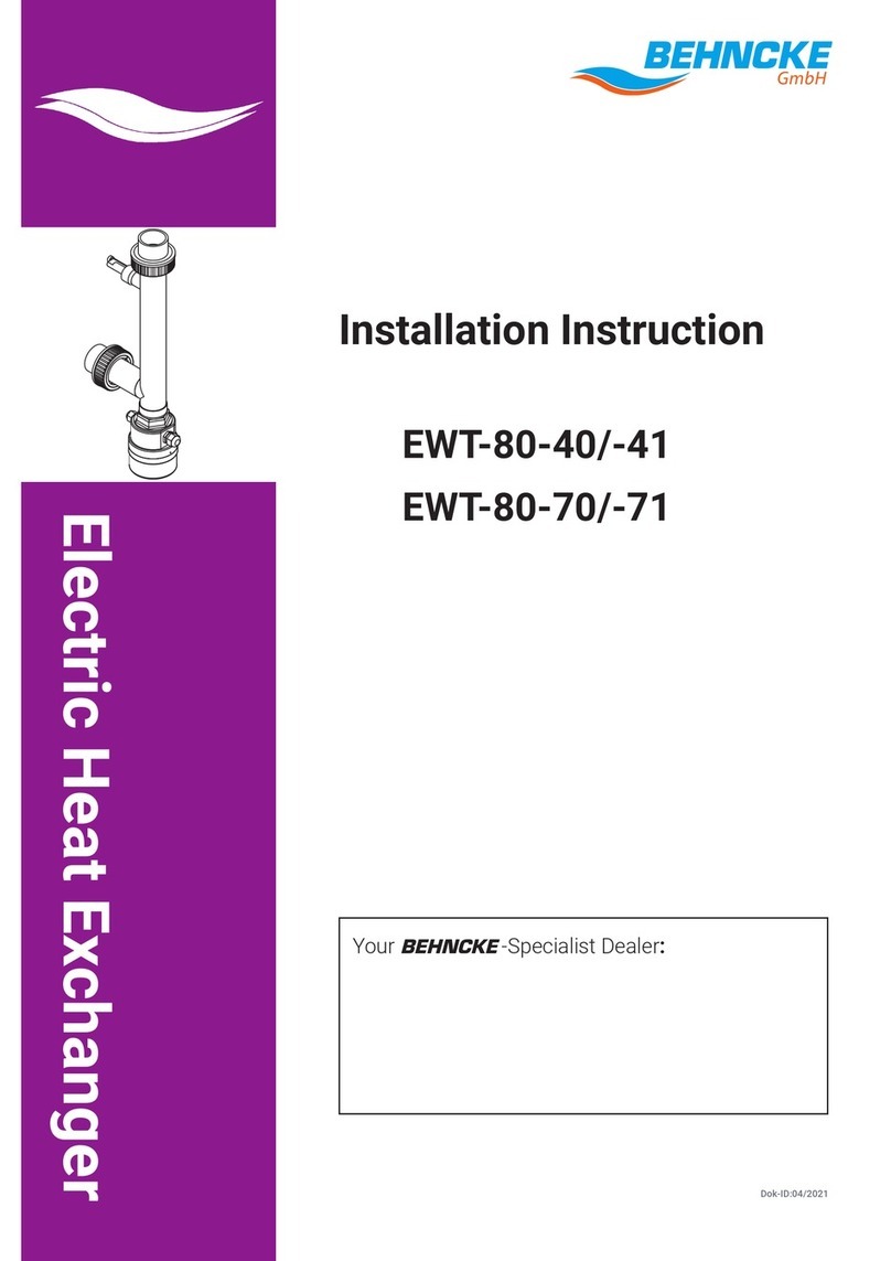
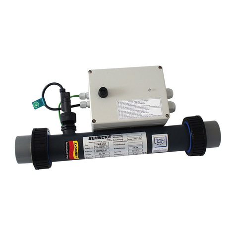
Behncke EWT 95-15 User manual

Installation Instruction
Electric Heat Exchanger
Electric/Swimming Pool Water
EWT 95 - 15
Your BEHNCKE®Specialist Dealer
– Subject to technical alteration! –
Stand 03/2011

Version of March 2011
Dear costomer,
congratulations on purchasing your new, state-of-the-art
electric heat exchanger „Made in Germany“.
Behncke®GmbH has produced high-quality pro-
ducts for the public and private swimming pool and
whirlpool sector for more than 30 years.
Your Behncke®specialist dealer will always give you
advice and support.
Please read this installation instruction with great care.
Store the installation instruction for future use!
Subject to technical alteration!

Inhaltsverzeichnis
27
Table of contents
1 Safety 28
1.1 Risks When Handling Electric Heat Exchanger 28
1.2 Safety Instructions and Information 28
1.3 Intended Use 29
1.4 Sources of Danger 30
1.5 Safety Measures on the Installation Site 30
1.6 Safety Equipment 30
2 Technical Data 31
2.1 EWT 95 - 15 31
3 Set-up/Installation 32
3.1 Transportation/Storage 32
3.2 Set-up and Installation Dimensions 32
3.3 Set-up 33
3.4 Installation 33
3.5 Water Connection 34
3.6 Electrical connection 35
4 Funcional Course 36
5 Service control unit 37
6 Initial Operation 40
7 Maintenance/Repair 40
7.1 Hibernation of the EWT in Frost-proof Rooms 40
7.2 Hibernation of the EWT in Non Frost-proof Rooms 41
8 Troubleshooting 42
9 Circuit Diagram 43
9.1 Connection with Kombi Filter controlling 43
9.2 Connection without Kombi Filter controlling 44
10 Explosion Drawings and Piece Lists 45
10.1 Piece list EWT 95 - 15 46

Safety
28
1 Safety
1.1 Risks When Handling Electric Heat Exchanger
The electric heat exchanger has been built on the basis of state-of-the-art techno-
logy and the approved safety-technical guidelines. Nevertheless, risk might occur
during use such as
- violation of operator or
- third parties
- impairments in electric heat exchanger or
- damage to other material values.
All persons, who are engaged in installation, initial operation, operation, mainte-
nance and repair of the electric heat exchanger, have to:
- be suited accordingly, mentally and physically.
- be qualified accordingly
- strictly observe these installation instructions.
The electric heat exchanger may only be used
- for the intended purpose.
- in a perfect safety-technical state.
In the case of disorders, which might impair safety, a sanitary expert is to be con-
sulted.
It is your safety!
1.2 Safety Instructions and Information
The following symbols are used in this safety instruction:
This symbols means warning of dangerous electric high power to the health of
persons.
Non-observance of this information might lead to severe injury
This symbol means possible danger to the health of persons.
Non-observance of this information might lead to severe injury
This symbol means a possible hazard for the health of persons.
Non-observance of this information might lead to injury to persons, or damage to
things.
This symbol gives important information for correct handling of the system.
Non-observance of this information might lead to disorders in the system or the
environment.
Warnung Vorsicht Gefahr
Warnung Vorsicht Gefahr
Warnung Vorsicht Gefahr
take care
take care

Safety
29
1.3 Intended Use
The electric heat exchanger is exclusively designed for heating bathwater with acti-
vated recirculating or filter pump.
Any other mode of application is not regarded as intended use. The manufacturer
Behncke ®GmbH is not liable for any resulting damage.
Other uses are only possible upon agreement with and approval by the
manufacturer.
Important!
The intended use also includes
- observance of all pieces of information in the installation instructions and
- execution of inspection and maintenance activities
Maximum permissible operational overpressure of 3 bar must not be exceeded.
Minimum permissible operational overpressure of 0.1 bar must be achieved.
The minimum throughput is 5000 l/h.
Water with the following values may only be used
Chloride content max. 500 mg/l
Free cholorine max. 1.3 mg/l
pH value 6,8 – 7,8
Retrofits and changes in the heat exchanger are prohibited for safety reasons.
For safety reasons, maintenance and repair activities in piping and electrical installati-
on are only to be executed by specialist personnel

Safety
30
1.4 Sources of Danger
The electric heat exchanger can be damaged.
If the maximum operational pressure of 3.0 bar is exceeded, the electric heat
exchanger might develop leaks.
The risk of burns exist.
The connections and the electric heat exchanger might reach temperatures of up
to 100°C.
In the case of insufficient throughput (<5000 l/h) strong overheating of the electric
heat exchanger is possible.
The electric heat exchanger might be damaged.
If dripping water falls onto the outer skin or if metal particles enter the electric heat
exchanger, the risk of contact corrosion exists.
1.5 Safety Measures on the Installation Site
The electric heat exchanger is to be installed in a frost-proof room with a mounting
device made of plastic or stainless steel.
Please ensure that the maximum operational overpressure of 3.0 bar is not
esceeded.
The electric heat exchanger or the environment can be damaged.
Please check the electric heat exchanger and its connections for tightness and
visible damage once a week during operation.
The danger of combustion exists.
In the case of insufficient throughput (<5000 l/h) strong overheating of the electric
heat exchanger is possible.
Do not store any combustible materials in the environment.
The electric heat exchanger can be damaged.
The electric heat exchanger may only be put into operation if it has been ensured
that the electric heat exchanger is continuously supplied with water during operati-
on. The water troughput must be at least 5000 l/hour.
1.6 Safety Equipment
The electric heat exchanger must be protected by at least two safety circiut
breakers.
The following safety circuit breakers built in by the factory
- a control thermostat, a safety temperature limiter and a flow control switch
The safety devices switch off the electric heat exchanger if impermissible values
are reached.
take care
take care
take care
take care
take care
take care
take care

Technical Data
31
2 Technical Data
2.1 EWT 95 - 15
Article Power in KW Supply Temperature Article No.
Voltage Selection
in Volt in °C
EWT 95 -15 18 230/400 – 302 051 18
EWT 95 -15 27 230/400 – 302 051 27
EWT 95 -15 36 230/400 – 302 051 36
EWT 95 -15 45 230/400 – 302 051 45

Set-up/Installation
32
3 Set-up/Installation
3.1 Transportation/Storage
Transport the electric heat exchanger only after it has been drained.
Store the flushed and drained electric heat exchanger in interior rooms with
non-aggressive atmosphere only.
3.2 Set-up and Installation Dimensions
Article KW A B C
mm mm Kombi
Socket
EWT 95 -15 18 560 275 d50/11/2”
EWT 95 -15 27 560 275 d50/11/2”
EWT 95 -15 36 675 390 d63/2”
EWT 95 -15 45 845 560 d63/2”

33
Set-up/Installation
3.3 Set-up
Set up the electric heat exchanger in frost-proof and dry rooms with non-agressive
atmosphere only. Dripping water might damage the electric heat exchanger.
Ensure easy access for installation and removal purposes.
The following water values are to be observed for the electric heat exchanger.
EWT 60-20/30
Chloride contents max. up to 500 mg/l
Free chlorine max. up to 1,3 mg/l
pH Value 6,8 – 7,8
Water troughput min. 5000 l/h
Maximum operational overpressure 3,0 bar
The risk of combustion exits in the case of a failure of the safety devices.
Overheating of the electric heat exchanger might cause a fire.
Draining of the electric heat exchanger during operation must be prevented.
Do not store any combustible material in the enviroment.
3.4 Installation
Check the electric heat exchanger before installation for visible damage.
The electric heat exchanger can be installed horizontally above or below water
level.
take care
take care

Set-up/Installation
34
3.5 Water Connection
3.5.1 Installation Layout Above the Water Level
Figure: horizontal installation
Figure: horizontal installation
3.5.2 Installation Layout Below the Water Level

Set-up/Installation
3.5.3 Connecting the Electric Heat Exchanger to the Water Cycle of a
Filter System
Install the electric heat exchanger in the pressure line (to the basin) after pump and
filter.
The electric heat exchanger is integrated into the water cycle with PVC
glued/screwed connections.
The electric heat exchanger can be damaged.
When the heat exchanger is connected to the water cycle, please take care that
metal particles do not enter the electric heat exchanger.
The electric heat exchanger might be damaged by chemicals.
Disinfecting devices are always to be installed in the flow direction after the
electric heat exchanger. The minimum distance must be 1 m and the order:
first water hardness control, than chlorine vaccination is to be observed.
If chemicals (e. g. chlorine gas) are used, gases must not enter the electric
heat exchanger during filter standstill times.
3.6 Electrical connection
The electrical connections are to be executed by an electrical specialist. Local
regulations as well as VDE 0100 are to be taken into consideration.
The electric heat exchanger must be connected on fixed power lines.
The electric heat exchanger must be connected durable and certain on the
ground wire.
The electric heat exchanger must be protected by at least two safety circuit
breakers.
The following safety circuit breakers built in by the factory
- a control thermostat, a safety temperature limiter and a flow control switch
Important!
It should be ensured that the electric heat exchanger can only be switched on if the
water throughput is ensured.
The electrical connections are to be effected in accordance with the switch
diagram.
For safety reasons, an FI safety switch is to be integrated into the voltage supply
(30 mA). All metal parts are to be integraded into equipotential bonding. It ist
absolutely recommended to built in a main protection (circuit diagramm, cap. 9).
By switching of the safety temperature limiter the EWT 95-15 is completely
switched off.
35
Warnung Vorsicht Gefahr
Warnung Vorsicht Gefahr
Warnung Vorsicht Gefahr
Warnung Vorsicht Gefahr
take care
take care
take care

Functional Course
36
4 Functional Course
In the electric heat exchanger, heat is transferred to the bathwater through the
heating element.
The thermostat regulates the water temperature in accordance with the adjusted
value, range from 4 to 40°C.
By pressing the I/O Button the EWT can be reseted after a breakdown. (LED
Störung is on)
The safety temperature limiter protects from overheating. It switches the electric
heat exchanger off at a temperature of 45°C.

Service control unit
37
5 Service control unit
Event
Pressing button O/I
Unit ON without
FP-running
(FP=filter pump)
Unit ON with
FP-running
(FP=filter pump)
Pressing button X
Pressing button +
Pressing button -
description
Unit is switched ON/OFF
Display shows AUS if the
unit is off
Display shows - 0 -
Display shows the actual
temperature of swimming
pool water
Display shows the target
value (automatically switched
back to actual value after
5 sec.)
If the target value is shown,
the value can be increased
by the + button (permanent
pressed increases the value
quickly)
If the target value is shown,
the value can be increased
by the - button (permanent
pressed decreases the value
quickly)
Symbol

Service control unit
38
Pressing buttons + and -
Pressing button AUTO
Pressing button HAND
Pressing button STUFEN
LED Heizung is flashing
LED Heizung is shining
LED Istwert is shining
LED Sollwert is shining
LED Störung is shining
Degree I is shining
Degree II is shining
If the buttons + and – are
pressed synchronous for 10
sec., display is flashing and the
actual value can be calibrated.
If the button AUTO is pressing
the heating power degree is
automatically selected
If the button HAND is pressing
the heating power degree can
be selected manually. If the
target value is not reached this
heating power degree would
be activated.
At manually selection the
degrees can be choosen
The heating is not activated
because the switch on delay
after starting the filter pump is
running (10 min)
The swimming pool water is
heating
Actual temperature of swim-
ming pool water is shown
Target value is shown. It can
be changed by buttons + and
-
If the security temperature
(45°C) exceeded this LED is
flashing. Could be reseted by
pressing button I/O
Heating of Water by heating
power degree I
Heating of Water by heating
power degree II

Service control unit
39
Degree III is shining
Display shows - 0 -
Display shows FP
Display shows US
Pressing buttons +,-,x
synchronous
Heating of Water by heating
power degree III
Cuurent ok, controller ok, filter
pump not running.
Filter pump is switched offlt
runs the running after time the
filter pump to avoid heating
dam*. To this the filter pump is
switched on 1 min by force.
Flow control switch is activa-
ted. Heating power is
switched off.
switch on delay (10 min) is
skipped.
*running after time to the filter pump only with Kombi-filter controller
(circuit diagram E 302.051.18/51 Chapter 9.1). Recommended.
At AUTO selection the heating power degree would be seleceted by following:
Degree I: The actual value is 0,2°C smaller than the target value.
Degree I and II: The actual value is 0,4°C smaller than the target value.
Degree I and II and II: The actual value is 0,6°C smaller than the target value.
If the target value is not reached by degree I or II after 2 hours, all heating power degree is
activated.

Initial Operation, Maintenance/Repair
40
6 Initial Operation
Have you read and understood these operating instructions – in particular chapter 1,
Safety? Only then are you allowed to start the electric heat exchanger.
• Adjust the desired bathwater temperature in the thermostat
The electric heat exchanger heats the bathwater as long as the adjusted tempera-
ture has not been reached,
The electric heat exchanger can be damaged.
Work in piping and electrical installation are only to be effected by specialist per-
sonnel for safety reasons.
Do not step on the heat exchanger.
Only carry out maintenance and repair work with closed blocking and control units
in the water cycle.
• Ventilate the water cycle
7 Maintenance/Repair
• Check the heat exchanger and its connections for their tightness once a week.
The electric heat exchanger can be damaged.
Work in the electrical heat exchanger are only to be effected by specialist person-
nel for safety reasons.
Do not step on the electric heat exchanger.
Only carry out work in the piping connections with closed blocking and control
units in the water cycle.
7.1 Hibernation of the EWT in Frost-proof Rooms
Intervention in technical systems by unqualified persons might lead to injury or
damage.
For hibernation in frost-proof rooms, the electric heat exchanger must be comple-
tely filled with water or be completely drained.
Warnung Vorsicht Gefahr
Warnung Vorsicht Gefahr
Warnung Vorsicht Gefahr
take care
take care
take care

Maintenance/Repair
41
7.2 Hibernation of the EWT in Non Frost-proof Rooms
Expert Hibernation without frost damage is possible if the following steps are
observed:
• Close blocking units in the water cycle (the blocking units must be
installed in frost-free rooms)
• Flush and drain electric heat exchanger and adjoining pipes until blocking units.
7.2.1 Electric Heat Exchanger with Horizontal Layout
• Remove heat exchanger with horizontal layout.
• Flush heat exchanger in order to remove contamination and
store in a dry place.

Troubleshooting
42
8 Troubleshooting
Effects Checking the possible cause
No performance is te electric heat exchanger connected to the
electrical supply?
have the blocking units been opened?
is the electric heat exchanger completely filled with water?
has the electric heat exchanger been ventilated?
is there sufficient flow (see Technical Data) in the electric
heat exchanger?
Electric heat has the lock between bathwater pump and electrical heat
exchanger is exchanger been activated?
further heated
up, despite
deactivated
bathwater
recirculating
pump

43
Cirquit Diagram
9 Cirquit Diagram
9.1 Connection with Kombi Filter controlling

Cirquit Diagram
44
9.2 Connection without Kombi filter controlling
Table of contents
Other Behncke Industrial Equipment manuals
