Behringer Intelligate XR2000 User manual
Other Behringer Extender manuals
Behringer
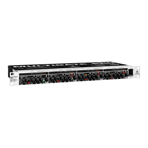
Behringer MULTIGATE PRO XR4400 User manual
Behringer
Behringer MULTICOM PRO-XL MDX4600 User manual
Behringer
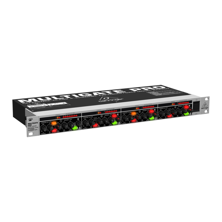
Behringer MULTIGATE PRO XR4400 User manual

Behringer
Behringer Preamp Booster PB100 User manual

Behringer
Behringer Intelligate XR2000 User manual
Behringer
Behringer COMPOSER PRO-XL MDX2600 User manual
Behringer
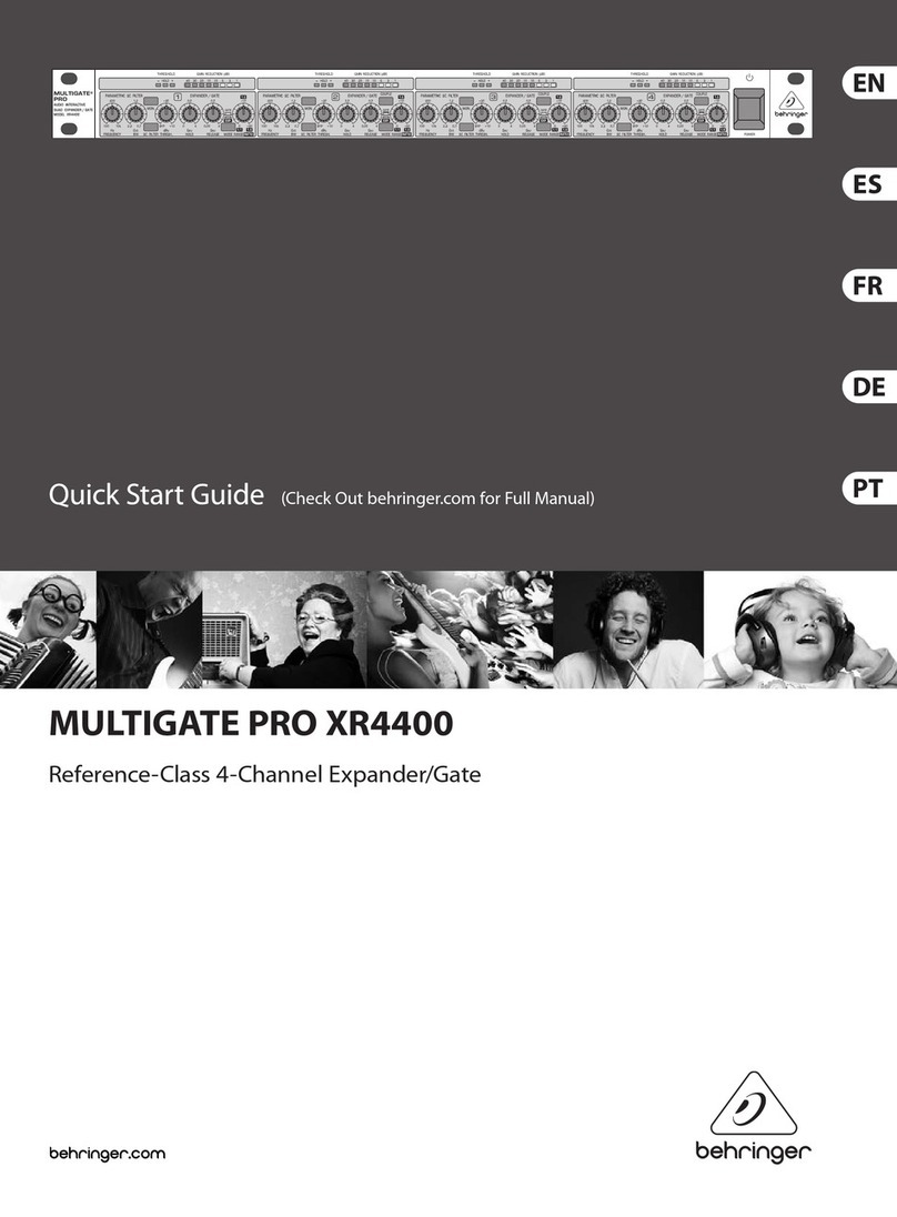
Behringer MULTIGATE PRO XR4400 User manual

Behringer
Behringer MULTIGATE PRO XR4400 User manual
Popular Extender manuals by other brands

foxunhd
foxunhd SX-AEX01 operating instructions

TERK Technologies
TERK Technologies LFIRX2 owner's manual

Devolo
Devolo Audio Extender supplementary guide

Edimax
Edimax EW-7438RPn V2 instructions

Shinybow USA
Shinybow USA SB-6335T5 instruction manual

SECO-LARM
SECO-LARM ENFORCER EVT-PB1-V1TGQ installation manual


