BEIFANG VALVE ACTUATOR 810 Series User manual
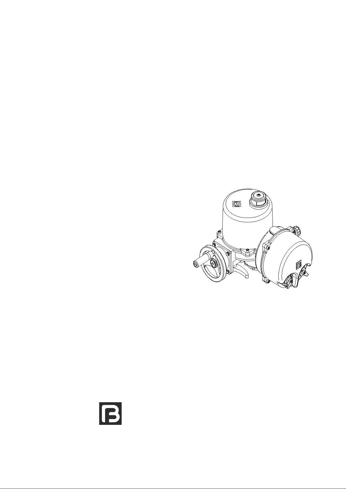
810 SERIES ELECTRIC ACTUATORS
WITH CONTROL PACKAGE
INSTRUCTION MANUAL
TIANJIN BEIFANG VALVE ACTUATOR CO., LTD.
Issue 201202
BFSE810-03
This manual should be used together with
《810 series electric actuators instruction manual》.

Tianjin Beifang Valve Actuator Co., Ltd. 1
810 series electric actuators with control package
Thank you for purchasing
and using our products. This
manual is valid for the control
package of 810 series electric
quarter-turn actuators.
Please tell us some information about your product when contact
with us:
Model, Factory Number, Production Date, etc.
Contents
Warnings and notes
This sign means:Hint!
Explain the topic in detail.
This sign means :Note!
Non-observance of these notes may lead to the
blight to products or the failure of operation.
This sign means :Warning!
If not carried out the “warnings” correctly can affect
the safety of persons or material.
Non-observance of the warnings and notes may lead to
serious injuries or damages. Qualified personnel must be
thoroughly familiar with all warnings and notes in these
operation instructions.
61.4.4 Advanced settings
51.4.2 Technical data
71.4.5 Factory default
51.4.3 Settings and calibration
1.4.1 Major function 4
72. Installation and debugging
41.4 Regulating module
31.3 Functional module
21.2 Control knob
21.1 Structure of the control package
21. Functions and operating instructions
Tianjin Beifang Valve Actuator Co., Ltd. 2
810 series electric actuators with control package
远程/停/现场旋钮
锁片
锁孔
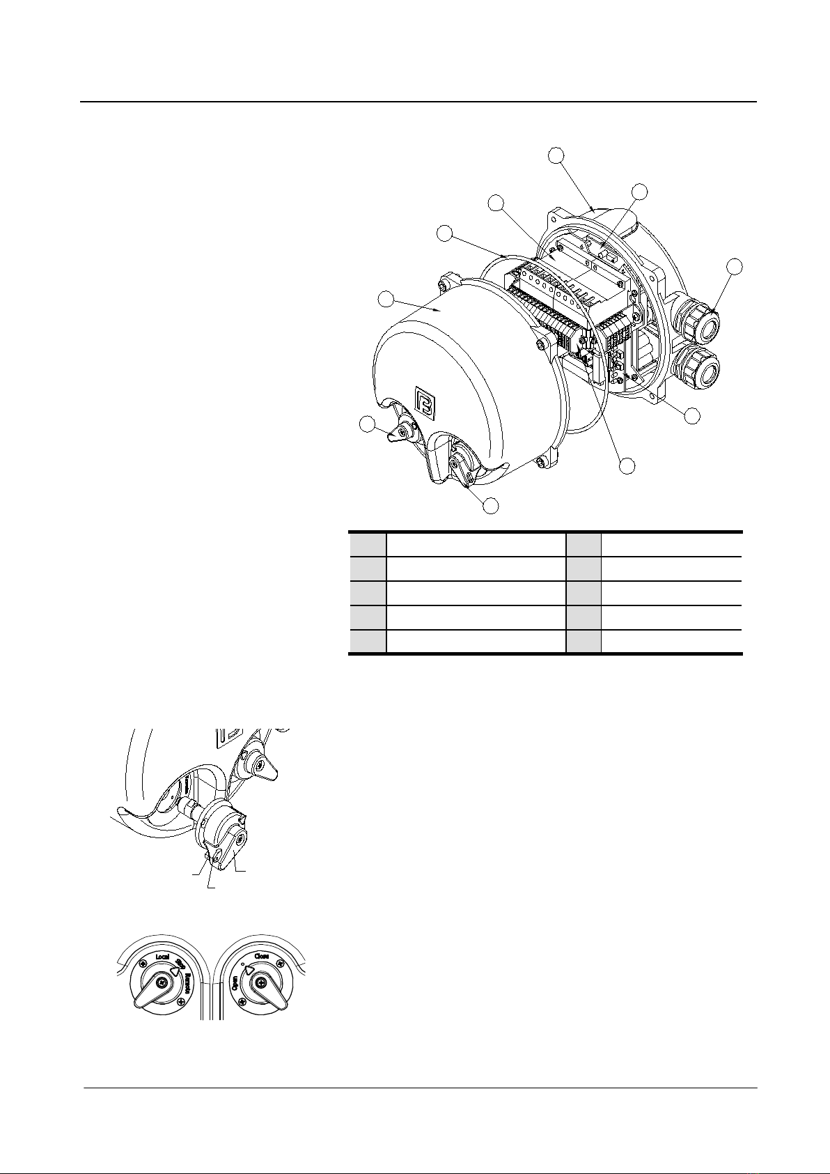
Functional module10“Local/Stop/Remote” selector5
Cable connector9Package cover4
Regulating module8Seal ring3
Terminal strips7Components group2
Local control knob
6Control box1
1.1 Structure of the control package 2
1
3
4
5
6
7
8
9
10
The package cover ④is equipped with a “Local/Stop/Remote”
selector ⑤and an open/stop/close local control knob ⑥. The
selector in three positions can be locked to prevent from mistaken
operation.
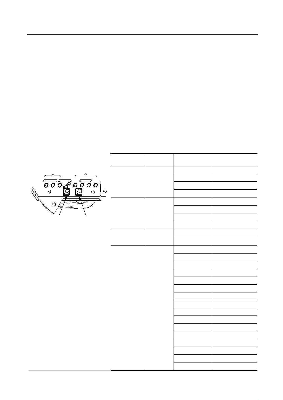
1.2 Control knob
• When the selector ⑤is in “Remote”, the Local control knob ⑥
doesn’t work and the product is in the remote operation condition.
• When the selector ⑤is in “Local”, turning the local control knob
⑥may control the actuator in site.
• When the selector ⑤is in “stop”, the actuator can’t be remote or
local operated.
1. Functions and operating instructions
The selector ⑤can be locked when push in the locking piece.
Remote/Stop/Local
selector
Locking piece
Lockhole
Tianjin Beifang Valve Actuator Co., Ltd. 3
810 series electric actuators with control package
Flashes three times and intermittent once.Over-current
Does not light.Other faults
Intermittent flashes.Loss of phase
Flashes twice continuously.Misphase
Lights. Normal
State of indicatorFault type
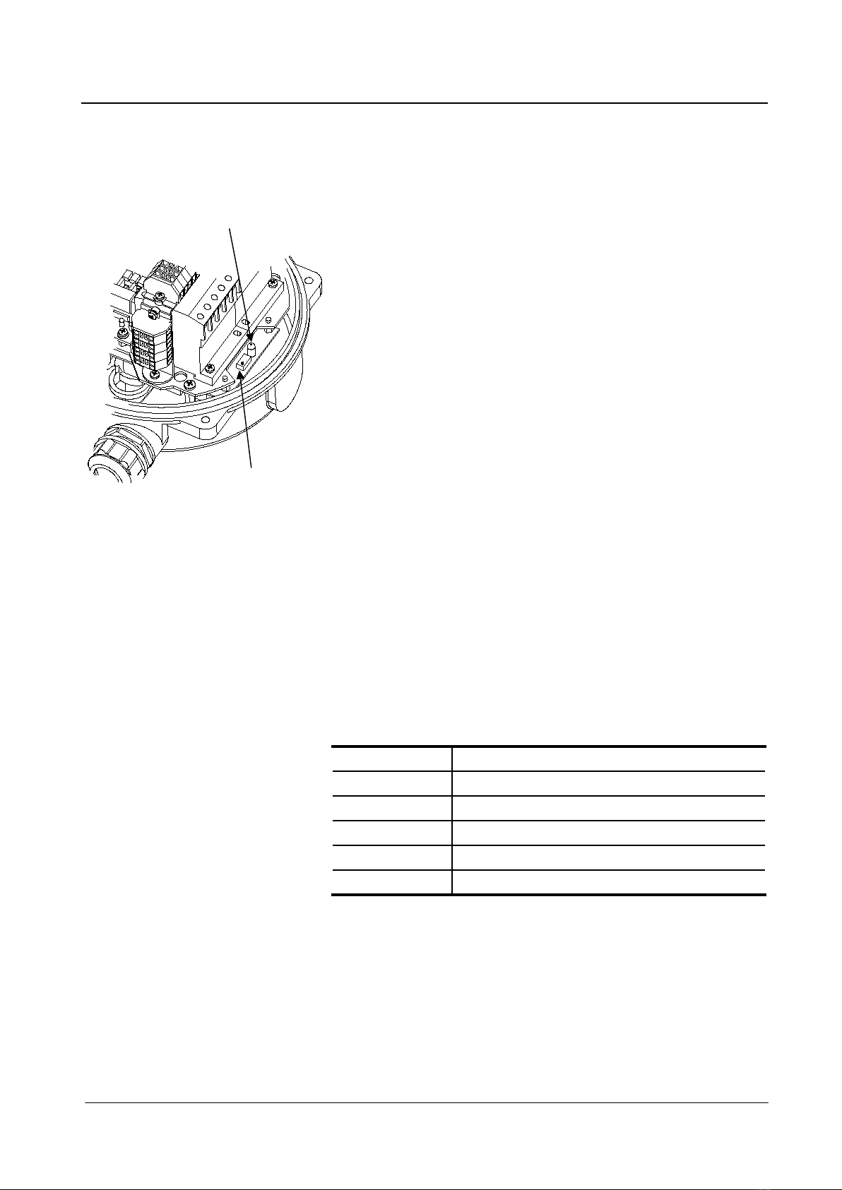
The functional module with functions of sequence identification,
missing-phase protection and over-current protection consists of
transformer, relay, singlechip, unicircuit, etc.
·Sequence identification and missing-phase protection (only for
three-phase power products).
The functional module real-time monitor the power sequence and
missing-phase fault. Once the fault appears, the module will cut off
the control circuit, at the same time prompt the fault type by
function indicator.
·Over-current protection
Motor stall or other reasons may lead to motor current rising rapidly
and even burning motor. The functional module real-time monitor
the line current of the motor. When the current exceeds the control
value and for one second, the module will judge to be the over-
current fault and cut off the control circuit, at the same time prompt
the fault type by function indicator.
1.3 Functional module
The potentiometer in the functional module is for setting the current
control value, which was set at the factory. Please don’t adjust this
value freely, so as not to affect the normal use.
The functional module will re-test after 10 minutes of over-current
protection. If the fault has been ruled out, the actuator will be back
to normal work.
When the actuator is energized the first time, the functional module
tests for 3 seconds and the indicator flashes 3 times, then the
actuator begins to work properly.
• State table of function indicator:
Potentiometer
Indicator light

Tianjin Beifang Valve Actuator Co., Ltd. 4
810 series electric actuators with control package
1.4.1 Major function The module proportional control the valve by receiving 4~20mA (or
0~5V) signal. With embedded CPU system, the module has
features of high precision, rich functions and great applicability.
•Auto-adjusting the accuracy
According to its own parameters, the valve position signal, the
control input signal and the mechanical error, the module auto-
adjust the tracking accuracy by optimization.
•Adjustable sensitivity
There are 16 grades to signal responding range (±0.5%, ±1%,
±1.5%, ±3%, ±4%, ±5%~±15%), the bigger the value, the
lower sensitivity you get. Users may set it according to control
need.
•Off signals protection (Note: 0~5V input signal has no this
function)
The input signal of less than 3mA is judged to be signal loss, which
will lead to system out of control, and even cause catastrophic
accidents. The module has the function of off signal protection, and
there are four choices in case of signal loss: keep in place, full open,
full close, middle position. The factory setting is keeping in
place.
•Running delay protection
The current shock of motor caused by instant start and stop leads
to the lack of tracking precision. The setting of running delay
protection is to reduce the lack and overcome the effect of inertia
of actuators. The delay time can be set to 2S, 3S, 4S and 5S. The
factory setting is 4S.
1.4 Regulating module The regulating module is only mounted in the
regulating product.
If users need to modify it, the running delay time should be set
greater than the inertia stopped time of actuators, otherwise it may
lower control accuracy although it can increase the response speed
of the module.

Tianjin Beifang Valve Actuator Co., Ltd. 5
810 series electric actuators with control package
1.4.2 Technical data
2S, 3S, 4S, 5S could be set.
Running
delay time
5
Adaptive adjustment of precision.
Control
accuracy
4
±0.5%, ±1%, ±1.5%, ±3%, ±4%~±15%, 16 grades
could be set.
Sensitivity3
Isolated 4~20mA, load capacity≤450ΩOutput
signal
2
4~20mA(or 0~5V), input impedance is 250Ω
Control
signal
1
DetailsItem
1.4.3 Settings and calibration
The zero and full must be calibrated before the
module putting into work, and the full must be
calibrated after the calibration of zero.
If the users need to replace the module, please connect wires
correctly according to the wiring diagram supplied with the actuators.
Set the module together with the operation of the actuator. When
the selector of actuator is in "Local", the module can only output
4~20mA valve position signal; When the selector is in "Remote", the
module can trace the input signal and analog regulate the valve
position. (Note: According to the different wiring diagram, when the
actuator is in "Remote" state, the inputting mode could be manual
or auto, the module can only work properly in "auto" mode.)
The module must be set after the setting of the limit switch and the
position indicator of the actuator (please refer to the instruction
manual provided with the valve actuator).
This module with strong and weak electricity must
only be installed in accordance with the applicable
rules by electricians who possess electrician safe
operation permits.
Tianjin Beifang Valve Actuator Co., Ltd. 6
810 series electric actuators with control package
Calibration steps
(The output signal 4mA corresponds to zero, 20mA corresponds to full.)
•Calibration the zero
Fully close the valve, then press the function key to make the
function indicator light as "Zero calibration" state, then press the
adjust key until the four adjust indicators flash and the zero
calibration is finished. At this time the output signal is 4mA.
•Calibration the full
Fully open the valve, then press the function key to make the
function indicator light as "Full calibration" state, then press the
adjust key until the four adjust indicators flash and the full
calibration is finished. At this time the output signal is 20mA.
•Return to auto working state
Press function key until the first indicator next to the function key
flashes, or without pressing any key for 30s, the module will
automatically return to the auto working state.
○
●
●
○
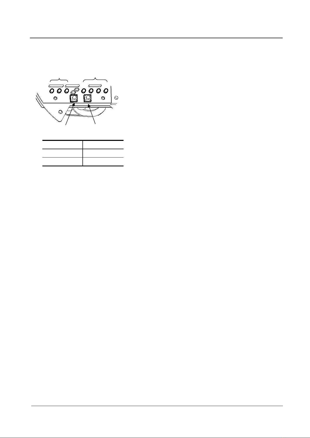
Function indicatorFunction
○
Calibration the full
○
Calibration the zero
●On 〇Off
Function
key
Function
indicator
Adjust
key
Adjust
indicator
After calibration and parameter setting, before the actuator putting
into use, the necessary adaptive operations are suggested to run to
adapt to inertia effect of different actuators (or the error is bigger
during the several initial use).
Set the actuators in "Remote" state, then input control signal (e.g.
10mA ~ 15mA) to make the valve run in a reciprocating way at least
four times.
The module can finely tune the output signal: Set the slide switch
SW1 to ON and the adjust indicators lighting shows the calibration is
finished and the fine-tuning can be carried out, here the function
and adjust keys are turned to "+" and "-" keys. Press the function
key to slightly increase the output signal and press the adjust key to
slightly reduce the output signal until outputting 4mA/20mA. Set the
slide switch SW1 to OFF to finish the zero/full fine-tuning.
1.4.4 Advanced settings
Please make sure that the operators are familiar with all parameters
before the advanced settings, or else normal operation of the
actuator could be affected.
Users can further flexible use the module by setting the parameters.
Tianjin Beifang Valve Actuator Co., Ltd. 7
810 series electric actuators with control package
①Unlock first : In the normal, pressing adjust key makes three
function indicators light and the four adjust indicators light after 5s,
thus open the parameter setting function.
②Press Function key repeatedly to make the three function
indicators show the state of setting the parameter.
③Press Adjust key repeatedly to make what the four adjusting
indicators show meets the setting need.
④Repeat the above steps to set other parameters.
⑤End of the parameter setting: Press Function key until to auto
working state, or automatically exit to auto working state without
pressing any key for 30s.
Setting steps
●
○
●
○
●
○
●
○
●
○
●
●
●
○
○
●
●
○
○
●
●
○
●
●
●
●
○
○
○
○
●
●
●
●
●
●
●
●
●
●
●
○
○
○
○
●
○
●
○
○
○
●
○
○
○
●
○
○
○
○
●
●
○
○
●
○
○
●
○
○
○
●
○
○
●
○
○
○
○
○
○
○
○
●
○
○
○
●
○
○
○
○
○
○
○
●
○
○
○
●
○
○
○
●
Adjust indicator
●
●
○
○
●
●
●
○
Setting value
Function
indicator
Setting parameters
15%
14%
13%
12%
11%
10%
9%
8%
7%
6%
5%
4%
3%
1.5%
1%
0.5%
○
Sensitivity
(The minimum
difference
between the input
signal to start the
valve and the
valve position
signal.)
4mA close, 20mA open.
4mA open, 20mA close.
●
Open mode
5s
4s
3s
2s
●
Delay
(The delay time of
re-start the motor.)
Set to middle position.
Set to full close.
Keep in place.
Set to full open.
●
Off signal
protection
(Set the valve
movement in case
of off signals.)
Function
key
Function
indicator
Adjust
key
Adjust
indicator
Indicators status:● On 〇Off

Tianjin Beifang Valve Actuator Co., Ltd. 8
810 series electric actuators with control package
If the factory settings are need to be restored, long press the
function and adjust keys at the same time while all indicators light
until all indicators go out after 10s.
The factory settings are:
4mA close
4S
Keep in place1.5%
Open modeDelay timeOff signalSensitivity
2. Installation and
debugging
Work on the electrical system or equipment must only
be carried out by an electrician who possess operating
certificate and operate in accordance with the
applicable electrical engineering rules.
Disconnect all incoming power to the unit prior to
opening the package cover.
Open the package cover carefully to avoid damaging
switches or terminals for the control knob is wiring the
terminal strip.
Installation with control package’s underside should
be avoided or the reliability and life time of the
contacts will be reduced.
When finish installation,connect wires according to the wiring
diagram supplied with the unit.
•Wire connection
Connect the wire to the terminal strip according to the wiring
diagram. The connection is finished if the wire can’t be pulled out.
•Debugging
Calibration the zero and full is necessary before the regulating
actuator is used. Please refer to the section 1.4.3 for the calibration
steps.
1.4.5 Factory default

Tianjin Beifang Valve Actuator Co., Ltd. 9
810 series electric actuators with control package
Address :Yi Xing Fu Science & Technology
Area Beichen District, Tianjin 300410, China
Tel:(022)26308907 26309159
Fax:(022)26300975
http://www.tj-beifang.com
e-mail: [email protected]
Tianjin Beifang Valve Actuator Co., Ltd
Table of contents
Other BEIFANG VALVE ACTUATOR Controllers manuals


