Beijer Electronics iX Panel K100 User manual

iXPanelK100
InstallationManual
English
MAEN995,2010-04

Foreword
InstallationmanualforiXPanelK100
Foreword
All iX Panels are developed to satisfy the demands of human-machine
communication. Built-in functions such as displaying and controlling text,
dynamic indication, time channels, alarm and recipe handling are included.
The operator panel works primarily in an object-oriented way, making it easy to
understand and use. Configuration is carried out on a PC using the iX Developer
configuration tool. The project can then be transferred and stored in the operator
panel itself.
Various types of automation equipment such PLCs, servos or drives can be
connected to the iX Panels. In this manual, the term “the controller” refers to the
connected equipment.
This manual explains how to install the operator panel. Please refer to the iX
Developer reference manual for further information.
© Beijer Electronics AB, MAEN995, 2010-04
The information in this document is subject to changewithoutnoticeandisprovidedasavailableatthe
time of printing. Beijer Electronics AB reserves the right to change any information without updating this
publication. Beijer Electronics AB assumes no responsibility for any errors that may appear in this document.
Read the entire installation manual prior to installing and using this equipment. Only qualified personnel
may install, operate or repair this equipment. Beijer Electronics AB is not responsible for modified, altered
or renovated equipment. Because the equipment has a widerangeofapplications,usersmustacquirethe
appropriate knowledge to use the equipment properly in their specific applications. Persons responsible
for the application and the equipment must themselves ensure that each application is in compliance with
all relevant requirements, standards and legislationinrespecttoconfigurationandsafety. Onlypartsand
accessories manufactured according to specifications set by Beijer Electronics AB may be used.
BEIJER ELECTRONICS AB SHALL NOT BE LIABLE TO ANYONE
FOR ANY DIRECT, INDIRECT, SPECIAL, INCIDENTAL OR
CONSEQUENTIAL DAMAGES RESULTING FROM THE
INSTALLATION, USE OR REPAIR OF THIS EQUIPMENT, WHETHER
ARISING IN TORT, CONTRACT, OR OTHERWISE. BUYER'S SOLE
REMEDY SHALL BE THE REPAIR, REPLACEMENT, OR REFUND
OF PURCHASE PRICE, AND THE CHOICE OF THE APPLICABLE
REMEDYSHALLBEATTHESOLEDISCRETIONOFBEIJER
ELECTRONICS AB .
BeijerElectronics, MAEN995

Contents
Contents
1 SafetyPrecautions ....................................................... 4
1.1 General ........................................................... 4
1.2 DuringInstallation .............................................. 4
1.3 DuringUse ....................................................... 5
1.4 Service and Maintenance ........................................ 5
1.5 Dismantling and Scrapping ..................................... 5
2 Installation ............................................................... 6
2.1 SpaceRequirements ............................................. 6
2.2 InstallationProcess .............................................. 6
2.2.1 ModeSwitches ................................................... 9
2.2.2 ConnectionstotheController .................................. 9
2.2.3 OtherConnectionsandPeripherals ............................. 9
3 TechnicalData ........................................................... 10
4 ChemicalResistance .................................................... 11
4.1 MetalCasing ..................................................... 11
4.2 Touch Screen and Overlay ....................................... 12
4.2.1 AutotexF157/207 ...............................................12
4.2.2 TouchScreenSurface ............................................13
4.2.3 AutoflexEB ......................................................13
5 OperatorPanelDrawings .............................................. 14
5.1 CommunicationPorts ........................................... 14
5.2 iXPanelK100Outline .......................................... 15
5.3 iX Panel K100 Text Strip ........................................ 16
6 Additional Installation Tips ............................................ 17
6.1 Grounding the Operator Panel ................................. 17
6.2 Ethernet Connection in the Panel .............................. 18
6.3 To Achieve Better EMC Protection ............................. 19
6.4 AmbientTemperature ........................................... 20
6.5 Safety ............................................................. 21
6.6 GalvanicIsolation ................................................ 22
6.7 Cable and Bus Termination RS485 ............................. 23
BeijerElectronics, MAEN995

Safety Precautions
1SafetyPrecautions
Both the installer and the owner and/or operator of the operator panel must read
and understand this installation manual.
1.1 General
•Read the safety precautions carefully.
•Check the delivery for transportation damage. If damage is found, notify the
supplier as soon as possible.
•Do not use the operator panel in an environment with high explosive hazards.
•The supplier is not responsible for modified, altered or reconstructed
equipment.
•Use only parts and accessories manufactured according to specifications of
the supplier.
•Read the installation and operating instructions carefully before installing,
using or repairing the operator panel.
•Neverallowfluids,metalfilingsorwiringdebristoenteranyopeningsinthe
operator panel. This may cause fire or electrical shock.
•Only qualified personnel may operate the operator panel.
•Storing the operator panel where the temperature is lower/higher than
recommended in this manual can cause the LCD display liquid to
congeal/become isotopic.
•The LCD display liquid contains a powerful irritant. In case of skin contact,
wash immediately with plenty of water. In case of eye contact, hold the eye
open,flushwithplentyofwaterandgetmedicalattention.
•Thefiguresinthismanualservesanillustrativepurpose. Becauseofthemany
variables associated with any particular installation, the supplier cannot
assume responsibility for actual use based on the figures.
•The supplier neither guarantees that the operator panel is suitable for your
particular application, nor assumes responsibility for your product design,
installation or operation.
1.2 DuringInstallation
•The operator panel is designed for stationary installation on a plane surface,
where the following conditions are fulfilled:
–no high explosive risks
–no strong magnetic fields
–no direct sunlight
–no large, sudden temperature changes
•Install the product according to the accompanying installation instructions.
•Ground the product according to the accompanying installation instructions.
•Only qualified personnel may install the operator panel.
•Separate the high voltage, signal and supply cables.
•Make sure that the voltage and polarity of the power source is correct before
connecting the product to the power outlet.
•Peripheral equipment must be appropriate for the application and location.
BeijerElectronics, MAEN995 4

Safety Precautions
1.3 DuringUse
•Keep the operator panel clean.
•Emergency stop and other safety functions may not be controlled from the
operator panel.
•Do not use too much force or sharp objects when touching the keys, touch
screen etc.
1.4 ServiceandMaintenance
•Only qualified personnel should carry out repairs.
•The agreed warranty applies.
•Before carrying out any cleaning or maintenance operations, disconnect the
equipment from the electrical supply.
•Clean the display and surrounding front cover with a soft cloth and mild
detergent.
•Replacing the battery incorrectly may result in explosion. Only use batteries
recommended by the supplier.
1.5 DismantlingandScrapping
•The operator panel or parts thereof shall be recycled according to local
regulations.
•The following components contain substances that might be hazardous
to health and the environment: lithium battery, electrolytic capacitor and
display.
BeijerElectronics, MAEN995 5

Installation
2Installation
2.1 SpaceRequirements
•Installation plate thickness: 1.5 - 9.0 mm (0.06 - 0.35 inch)
•Space requirements when installing the operator panel:
252 mm
58 mm
100 mm
(4.0 inch)
50 mm
(2.0 inch) 50 mm
(2.0 inch)
100 mm
(4.0 inch)
(9.92 inch)
382 mm
100 mm
(4.0 inch)
(15.04 inch) (2.28 inch)
Caution:
Theopeningsontheenclosureareforairconvection. Donotcovertheseopenings.
2.2 InstallationProcess
1. Unpack and check the delivery. If damage is found, notify the supplier.
x 14
Panel cut out 343 x 208 mm
(13.5 x 8.18 inch)
Note:
Placetheoperatorpanelonastablesurfaceduringinstallation.
Droppingitorlettingitfallmaycausedamage.
BeijerElectronics, MAEN995 6
Installation
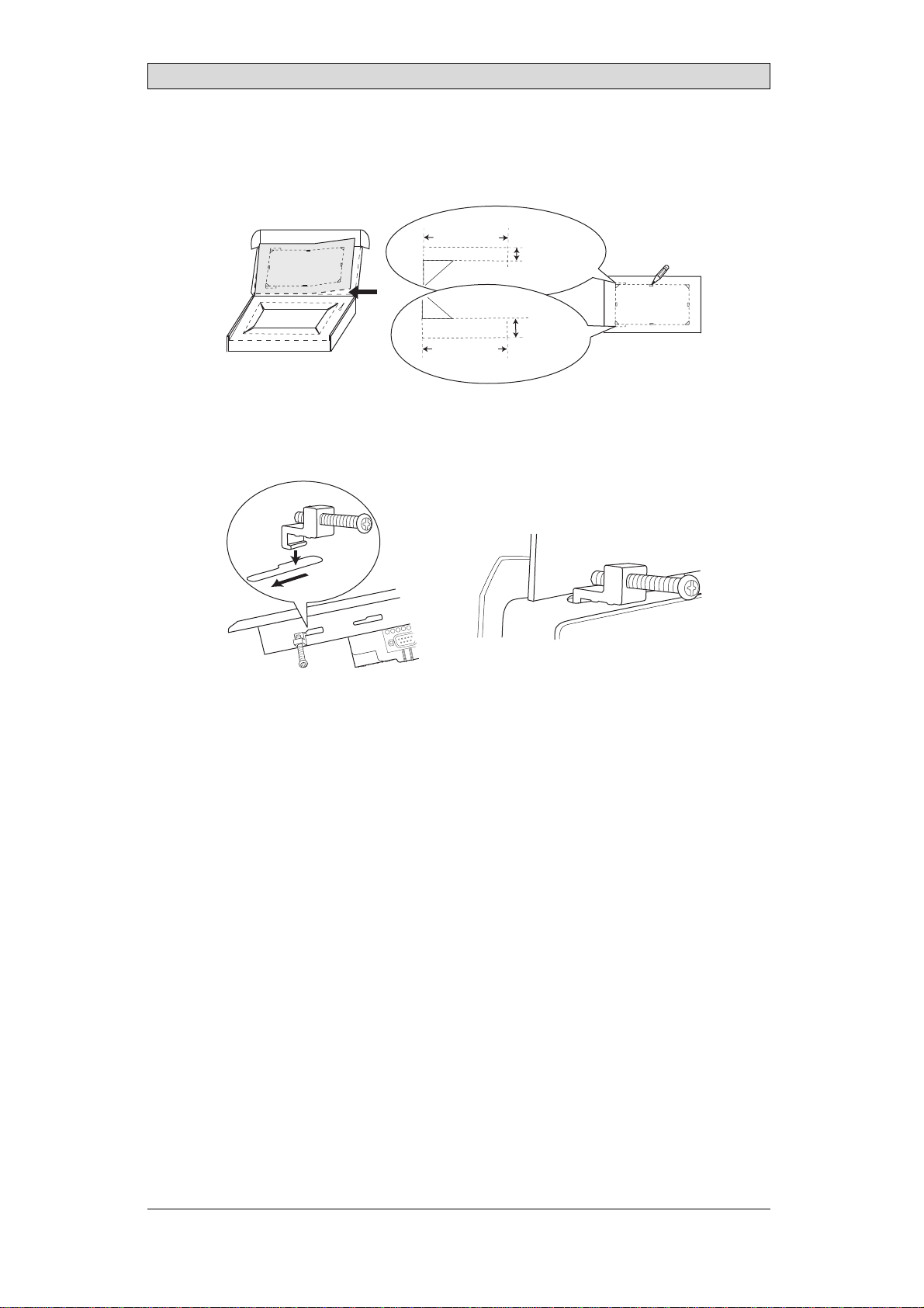
2. Place the panel cut out where the operator panel is to be situated, draw along
the outer sides of the holes and cut according to the markings.
6.5 mm
35.0 mm
For text strip
3.5 mm
35.0 mm
(1.38 inch)
(1.38 inch)
(0.14 inch)
(0.26 inch)
3. Secure the operator panel in position, using all the fastening holes and the
provided brackets and screws:
x 14
0.5 - 1.0 Nm
BeijerElectronics, MAEN995 7

Installation
4. Connect the cables in the specified order, according to the drawing and steps
below.
Caution:
•Ensurethattheoperatorpanelandthecontrollersystemhavethesameelectrical
grounding(referencevoltagelevel),otherwiseerrorsincommunicationmay
occur.
•Theoperatorpanelmustbebroughttoambienttemperaturebeforeitisstarted
up. Ifcondensationforms,ensurethattheoperatorpanelisdrybeforeconnecting
ittothepoweroutlet.
•Ensurethatthevoltageandpolarityofthepowersourceiscorrect.
•Useonlyshieldedcommunicationcables.
•Separatehighvoltagecablesfromsignalandsupplycables.
24V DC
RS422/RS485 24V DC
1
CF CARD
B
A
C
D
RS232
Controller
Power
Ethernet
–Connect cable A.
–Connect cable B, using an M5 screw and a grounding conductor (as short
as possible) with a cross-section of minimum 2.5 mm2.
–Connect cable C.
–Connect cable D.
5. Carefully remove the laminated film over the operator panel display, to avoid
static electricity that could damage the panel.
BeijerElectronics, MAEN995 8
Installation
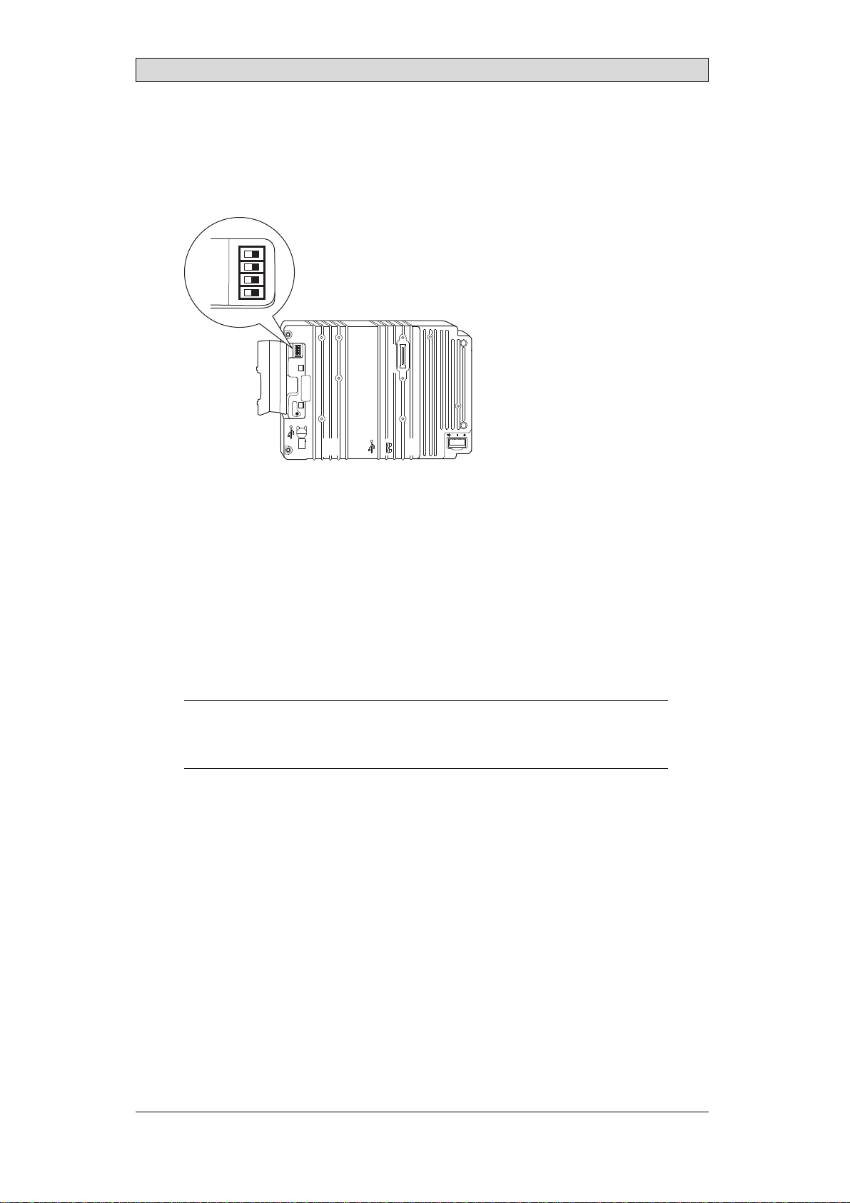
2.2.1 ModeSwitches
All mode switches must be in OFF position during operator panel use.
Themodeswitchesshouldnotbetouchedunlessbyqualifiedpersonnel.
1
24V DC
CF CARD
COM 1
RS422
RS485
COM 2
RS232
10/100
EXPANSION
BUSY
MODE
1 2 3 4
ON DIP
MODE
1 2 3 4
ON DIP
2.2.2 ConnectionstotheController
For information about the cablestobeusedwhenconnectingthe operator panel to
the controller, please refer to the help file for the driver in question.
2.2.3 OtherConnectionsandPeripherals
Cables, peripheral equipment and accessoriesmustbesuitablefortheapplication
and its environment. For further details or recommendations, please refer to the
supplier.
Caution:
Whenusingacompactflashcard,donotremovethecardwhenthebusyindicatoris
illuminated.
BeijerElectronics, MAEN995 9
Technical Data
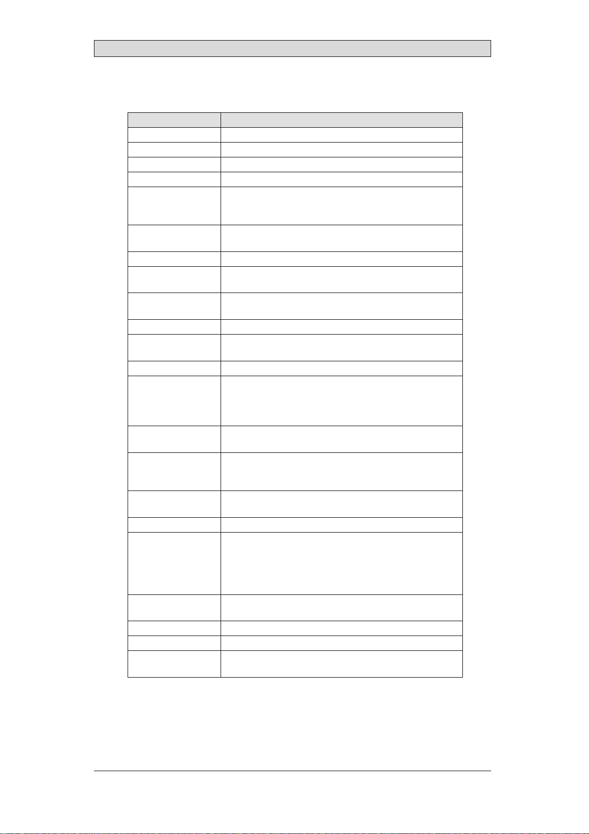
3TechnicalData
Parameter iXPanelK100
Frontpanel,WxHxD 382x252x6mm
Mountingdepth 58mm(158mmincludingclearance)
Frontpanelseal IP66
Rearpanelseal IP20
Keyboardmaterial Membraneswitchkeyboardwithmetaldomes. Overlay
filmofAutotexF157*withprintonreverseside. 1million
operations.
Reverseside
material Powder-coatedaluminum
Weight 2.5kg
Serialport
RS422/RS485 25-pinD-subcontact,chassis-mountedfemalewith
standardlockingscrews4-40UNC
SerialportRS232C 9-pinD-subcontact,malewithstandardlockingscrews4-40
UNC
Ethernet ShieldedRJ45
USB HosttypeA(USB1.1),maxoutputcurrent500mA
DevicetypeB(USB1.1)
CF-slot Compactflash,typeIandII
Realtimeclock ±20PPM+errorbecauseofambienttemperatureandsupply
voltage. Totalmaximumerror: 1min/monthat25°C.
Temperature coefficient: -0.034±0.006ppm/°C2
Rechargeablebattery.
Powerconsumption
atratedvoltage Normal: 0.5A
Maximum: 1.0A
Display TFT-LCD.800x600pixels,64Kcolors.
CCFLbacklightlifetimeattheambienttemperatureof
+25°C:>50,000h.
Activeareaof
display,WxH 211.2x158.4mm
Fuse InternalDCfuse,3.15AT,5x20mm
Powersupply +24VDC(20-30VDC).Powersupplyconnector.
CE:Thepowersupplymustconformwiththerequirements
accordingtoIEC60950andIEC61558-2-4.
ULandcUL:Thepowersupplymustconformwiththe
requirementsforclassIIpowersupplies.
Ambient
temperature Verticalinstallation: 0°to+50°C
Horizontalinstallation: 0°to+40°C
Storagetemperature -20°to+70°C
Relativehumidity 5-85%non-condensed
Approvalsand
certifications Informationisavailableonthewebsite
www.beijerelectronics.com
*SeesectionChemicalResistanceformoreinformation.
BeijerElectronics, MAEN995 10
Chemical Resistance
4 ChemicalResistance
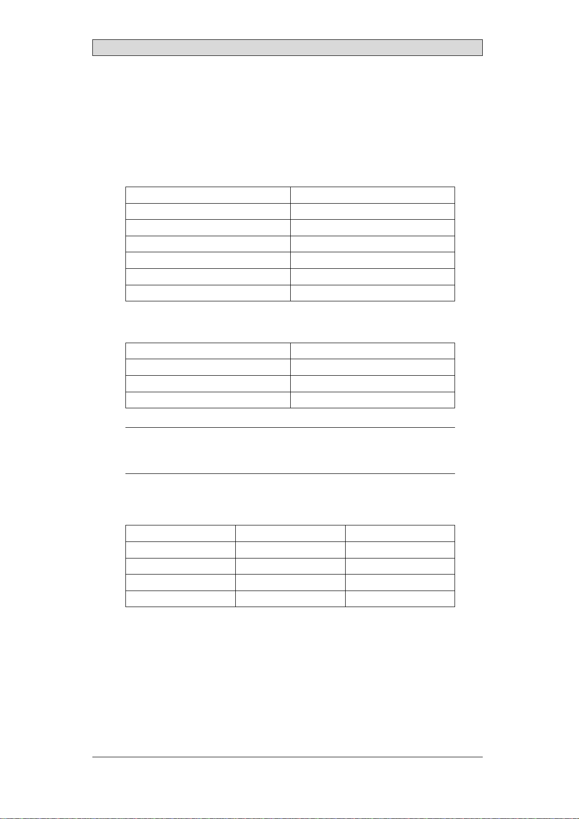
4.1 MetalCasing
The frame and casing material is powder-coated aluminum. This powder paint
withstands exposure to the following chemicals without visible change:
Aceticacid10% Phosphoricacid4%
Citricacid10% Phosphoricacid10%
Diesel Seawater
Distilledwater Sodiumchloride2%
Edibleoil Sodiumchloride20%
Fueloil Sulphuricacid20%
Hydrogenperoxide3% Tapwater
The powder paint shows limited resistance to the following chemicals at room
temperature:
Butanol Nitricacid3%
Hydrochloricacid5% Nitricacid10%
Isopropylalcohol Phosphoricacid43%
Na-hypochlorite10% Turpentine
Note:
Ifexposuretoanyoftheabovechemicalsisdemanded,itisrecommendedtofirsttest
thechemicalonan“invisible”spotofthemetalcasing.
Thepowderpaintshowslittleornoresistancetothefollowingchemicalsatroom
temperature:
Aceticacid,conc. Methyl-ethylketone Toluene
Acetone Nitricacid30% Trichlorethylene
Ammonia5% Phenol Xylene
Ammonia,conc. Sodiumhydroxide5% 97octanunleadedpetrol
Ethylacetate Sodiumhydroxide30% 98octanleadedpetrol
BeijerElectronics, MAEN995 11

Chemical Resistance
4.2 TouchScreenandOverlay
4.2.1 AutotexF157/207
Autotex F157 or F207 covers the overlay surrounding the touch screen.
SolventResistance
Autotex F157/F207 withstands exposure of more than 24 hours duration under
DIN42115Part2tothefollowingchemicalswithoutvisiblechange:
Acetonitrile DieselDowney/Lenor1Phosphoricacid(<30%)
Ajax/Viminsolution EthanolPotassiumferricyanide
Alkalicarbonatesolution1Glycerine Potassiumhydroxide
(<30%)
Ammonia(<40%)1Glycol PureTurpentine
Aceticacid(<50%) Gumption1SBP60/951
Arielpowderinsolution1Hydrochloricacid(<36%) Sulfuricacid(<10%)
Bleach1Linseedoil Tomatoketchup
Castoroil Methanol Trichloroaceticacid
(<50%)
Causticsoda(<40%)1Nitricacid(<10%) WhiteSpirit
Cuttingoil Paraffinoil Windex1
Cyclohexanol Persilpowderinsolution1Wisk
Diacetonealcohol Petroleumspirit1-
1Extremely faint glossing of the texture was noted.
Autotex withstands DIN 42 115 Part 2 exposure of up to 1 hour duration to glacial
acetic acid without visible change.
Autotex is not resistant to high pressure steam at over 100 °C or the following
chemicals:
Concentratedmineralacids Benzylalcohol
Concentratedcausticsolution Methylenechloride
OutdoorUse
In common with all polyester based films Autotex F157/F207 is not suitable for
use in conditions of long term exposure to direct sunlight.
BeijerElectronics, MAEN995 12

Chemical Resistance
4.2.2 TouchScreenSurface
Thetouchscreensurfaceonthepanelwithstandsexposuretothefollowing
solvents without visible change:
Solvents Time
Acetone 10minutes
Isopropanol 10minutes
Toluene 5 hours
4.2.3 AutoflexEB
It is recommended to use the Autoflex EB touch display protection film, that can
be ordered from Beijer Electronics.
SolventResistance
Autoflex EB withstands exposure to the same chemicals as Autotex F157 or F207
according to section Autotex F157/207.
OutdoorUse
In common with all polyester based films Autotex EB is not suitable for use in
conditions of long term exposure to direct sunlight.
BeijerElectronics, MAEN995 13

Operator Panel Drawings
5 OperatorPanelDrawings
5.1 CommunicationPorts
RS-232
RS-422
RS-422/485 RS-485
Ethernet
USB
BeijerElectronics, MAEN995 14

Operator Panel Drawings
5.2 iXPanelK100Outline
BeijerElectronics, MAEN995 15

Operator Panel Drawings
5.3 iXPanelK100TextStrip
BeijerElectronics, MAEN995 16
Additional Installation Tips
6 AdditionalInstallationTips
When experiencing communication problems in for example noisy environments
or when operating close to temperature limits, the following recommendations
are to be noticed.
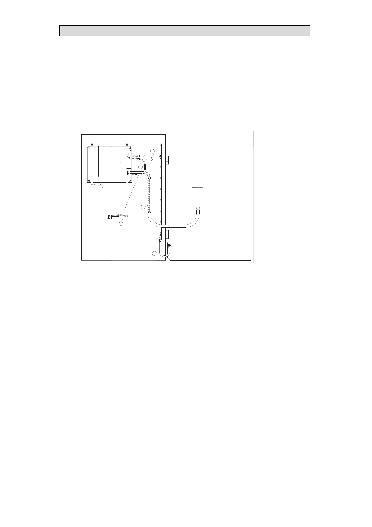
6.1 GroundingtheOperatorPanel
1
2
3
4
5
6
Door
Operator panel
Ferrite core
Mounting plate in the cabinet
Power supply
24 V DC
5350
The operator panel’s mounting clamps do not provide a secure grounding
connection between the panel and the device cabinet, see 1 in drawing above.
1. Connect a 2.5 mm2wire between the operator panel’s quick-connect plinth
and the panel chassis, see 2 in drawing above.
2. Connect a 6 or 4 mm2wire or grounding braid between the panel’s chassis and
the closest grounding point on the door, see 3 in drawing above.
3. Connect a strong but short grounding braid between the door and the device
cabinet, see 4 in drawing above.
4. Twist the cables onto the 24 V DC feed, see 5 in drawing above.
2 turns around the ferrite core provide 4 times the suppression of 1 turn.
3 turns around the ferrite core provide 9 times the suppression of 1 turn.
A ferrite core suppresses disturbances to the 24 V feed, see 6 in drawing above.
Note:
Thegroundingwiresshouldbeshortandtheconductorshouldhavealargearea.
Along,thingroundingwirehasaveryhighimpedance(resistance)athighfrequencies
andwillnotguidedisturbancestotheground.
Multi-wireconductorsarebetterthansinglewireconductorswiththesamearea.
Abraidedconductorwirewiththesameareaisevenbetter. Thebestisashort,thick
groundingbraid.
BeijerElectronics, MAEN995 17

Additional Installation Tips
6.2 EthernetConnectioninthePanel
1
2
3
4
5
1-1
2-2
3-3
8-8
RJ45
RJ45
RJ45
RJ45
RJ45
RJ45
RJ45
RJ45
Industrial Ethernet
Operator panel
Operator panel
Operator panel
Operator panel
Shielded Short and
unshielded
0.1 uF
250 V
5351
In some industrial units for Ethernet, the RJ45 contact’s shield is connected to the
chassis via a capacitor, see 1 in drawing above.
The operator panel’s Ethernet shield is directly connected to the chassis, see 2 in
drawing above.
1. Check whether the other Ethernet unit has its shield directly grounded or
grounded via a capacitor.
Note:
Inmanycases,connectingtheshieldedEthernetcablingtothechassisatbothendsis
inappropriate. Humorgroundingloopscanoccur. Unshieldedcablingmayevenresult
infewercommunicationerrors.
A good solution may be to use a shielded Ethernet cable, but to connect the shield
at one end only.
One option is to break the shield, see 3 in drawing above.
A more elegant method is to expand the shielded Ethernet cabling with a piece of
unshielded Ethernet cable, see 4 in drawing above.
You can ground the shield via an external 0.1 uF/250 V plastic capacitor, see 5 in
drawing above. This will connect the HF transients to the ground.
BeijerElectronics, MAEN995 18

Additional Installation Tips
6.3 ToAchieveBetterEMCProtection
•Initially, use the original cabling from Beijer Electronics primarily.
•Use shielded cables for RS232 communication.
•Use twisted pair and shielded cabling for RS422 and RS485.
•Use the cabling intended for the bus type; Ethernet, Profibus, CC-Link,
CAN, Device Net etc.
•Install and connect according to applicable specifications for the relevant bus
standard.
•Use shielded cabling for Ethernet, preferably with foil + braided shield.
•D-sub covers should be shielded, and the shield should be connected to the
cover 360 ° where the cable comes in.
•Connect the shield at both ends.
Shielded cable
Not same potential
Ground plane 1 Ground plane 2
Ground plate Ground plate
in another building
0.1 uF/250 V
5352
With longer distances, there is a risk that the ground potential may be different.
In that case, the shield should only be connected at one end. A good alternative
is to connect the other end of the shield to the ground via a 0.1 uF/250 V plastic
capacitor. Both ends are then connected to the ground in terms of HF, but only
connected to the ground at one end in terms of LF, thus avoiding the 50 Hz
grounding loops.
Metal cabinet Metal cabinet
Terminal or connector Terminal or connector
EMC cable gland Plastic cable gland
Shielded cable Shielded cable
Short distance
Cable clamp
in steel
5353
1. Use an EMC cable gland or regular plastic cable gland, remove the outer jacket
and connect the shield to the installation plate with a 360 ° metal cable clamp.
2. Place the 24 V DC and communications cabling in one cable trunk/cable duct
and 230/380 V AC in another. If the cables need to be crossed, cross them at
90 ° only. Avoid combining the cabling for stronger 24 V DC outputs with
the communication cabling.
Ferrite cores that are snapped onto the shielded cabling may remove minor
disturbances. Large ferrite pieces that are snapped onto unshielded cabling and
where the wires go 2-4 times around the cores are approximately 5-25 times more
efficient.
BeijerElectronics, MAEN995 19

Additional Installation Tips
6.4 AmbientTemperature
The maximum ambient temperature for the operator panel is provided in the
specifications. The ambient temperature refers to the temperature in the device
cabinet which cools the panel’s electronics.
Operator
panel Power
Power
Power
30 °C outside
Top
50 °C inside
Bottom
40 °C inside
Middle
45 °C inside
Airflow
Axial fan
120 x 120 mm
5354
Inmostcases,theambienttemperaturefortheoperatorpanelissignificantly
higher than the device cabinet’s ambient temperature.
If the cabinet is tall and there are a number of heat-generating devices, the
temperature at the top of the cabinet will be considerably higher than the
theoretical temperature increase that would be expected. All electronics are
sensitivetoheat. Thelifespanofanelectro
lytic capacitor is cut in half with an 8-10
° increase in temperature. A 15-20 ° temperature increase results in a quarter of the
lifespan etc.
Rittal has a good program for estimating the anticipated average temperature in
the cabinet as well as a large program for controlling the temperature in the device
cabinet.
An enamel-coated steel cabinet has a radiant heat value of 5.5 W/m2and degrees
C.
Installing a fan inside the cabinet will even out the temperature, while moving air
provides considerably better cooling than still air. A suitable fan is a 120 x 120 mm
axial fan, available in 24 V DC, 115 and 230 V AC.
Installthefansothatitsit
s in the cooler area and will blow cold air against the
operator panel. If the fan is mounted at the top and sucks air upwards, the fan’s
ambient temperature will be higher = shorter lifespan.
Agoodfanwithaball-bearingmountinghasanexpectedlifespanofatleast
40,000 hours (not a guaranteed lifespan) at 40 °C. This corresponds to at least 4
years of continuous use. If a thermostat is installed, the fan only needs to come
on when needed.
Large graphic terminals draw only one fifth of the current when the background
lighting is off. The loss effect drops from e.g. 25 W to only 5 W.
The operator panel’s loss effect = supply voltage x current. Virtually no power goes
to external users and no loss effects due to inputs.
BeijerElectronics, MAEN995 20
Other manuals for iX Panel K100
1
Table of contents
Popular Industrial Equipment manuals by other brands


BADU
BADU OmniTronic translation of original operation manual

Dover
Dover OPW 301 Series Installation and maintenance instructions

UNIFILLER
UNIFILLER Mini Dopositor Operation and Spare Parts Manual

Rexnord
Rexnord Stearns 1-081-X00 Series Resetting guide

Sony
Sony DG110BM instruction manual

Modine Manufacturing
Modine Manufacturing ECO EG quick guide

Sanuvox
Sanuvox SANUVAIR S600 instruction manual

Panametrics
Panametrics MG-101 user manual

Donaldson
Donaldson Torit MediaFilter Horizontal Series Installation and operation manual

SSI SCHAEFER
SSI SCHAEFER Cuby Assembly and operating manual

Desoutter
Desoutter 115DFL user manual

Festo
Festo DGE ZR-RF Series operating instructions