BeiJer GN-9289 User manual

Page 1 of (70)
G-series GN-9289 Modbus TCP_UDP Rev. 1.01.docx
Modbus TCP/UDP network adapter
GN-9289
User manual

GN-9289 User Manual
Page 2 of (70)
G-series GN-9289 Modbus TCP_UDP Rev. 1.01.docx
DOCUMENT CHANGE SUMMARY
REV.
PAGES
REMARKS
DATE
Editor
1.00
New Document
2018/7/30
1.01
First release
2019/01/29
NJL

GN-9289 User Manual
Page 3 of (70)
G-series GN-9289 Modbus TCP_UDP Rev. 1.01.docx
Contents
1.
Important Notes..............................................................................................................................................6
1.1.
Safety Instruction............................................................................................................................................ 7
1.1.1
Symbols ...............................................................................................................................................7
1.1.2
Safety Notes......................................................................................................................................... 7
2.
Specification ................................................................................................................................................... 8
2.1.1 GN-9289 (MODBUSTCP) .........................................................................................................................8
2.2.
General Specification......................................................................................................................................9
2.2.1
GeneralSpecification..........................................................................................................................9
2.2.2 Interface Specification......................................................................................................................10
2.3. GN-9289 LED Indicator .................................................................................................................................11
2.3.1
Module Status LED (MOD)................................................................................................................11
2.3.2
Physical Connection LED(LINK)......................................................................................................11
2.3.3
Exchange Data/Traffic Present LED(ACTIVE) .................................................................................12
2.3.5
Field Power Status LED....................................................................................................................12
3.
Dimension.....................................................................................................................................................13
3.1 GN-9289...........................................................................................................................................................13
4.
Mechanical Set Up........................................................................................................................................14
4.1 Total Expansion...............................................................................................................................................14
4.2. Plugging and Removal of the Components................................................................................................. 14
4.3 Module mounting ..........................................................................................................................................15
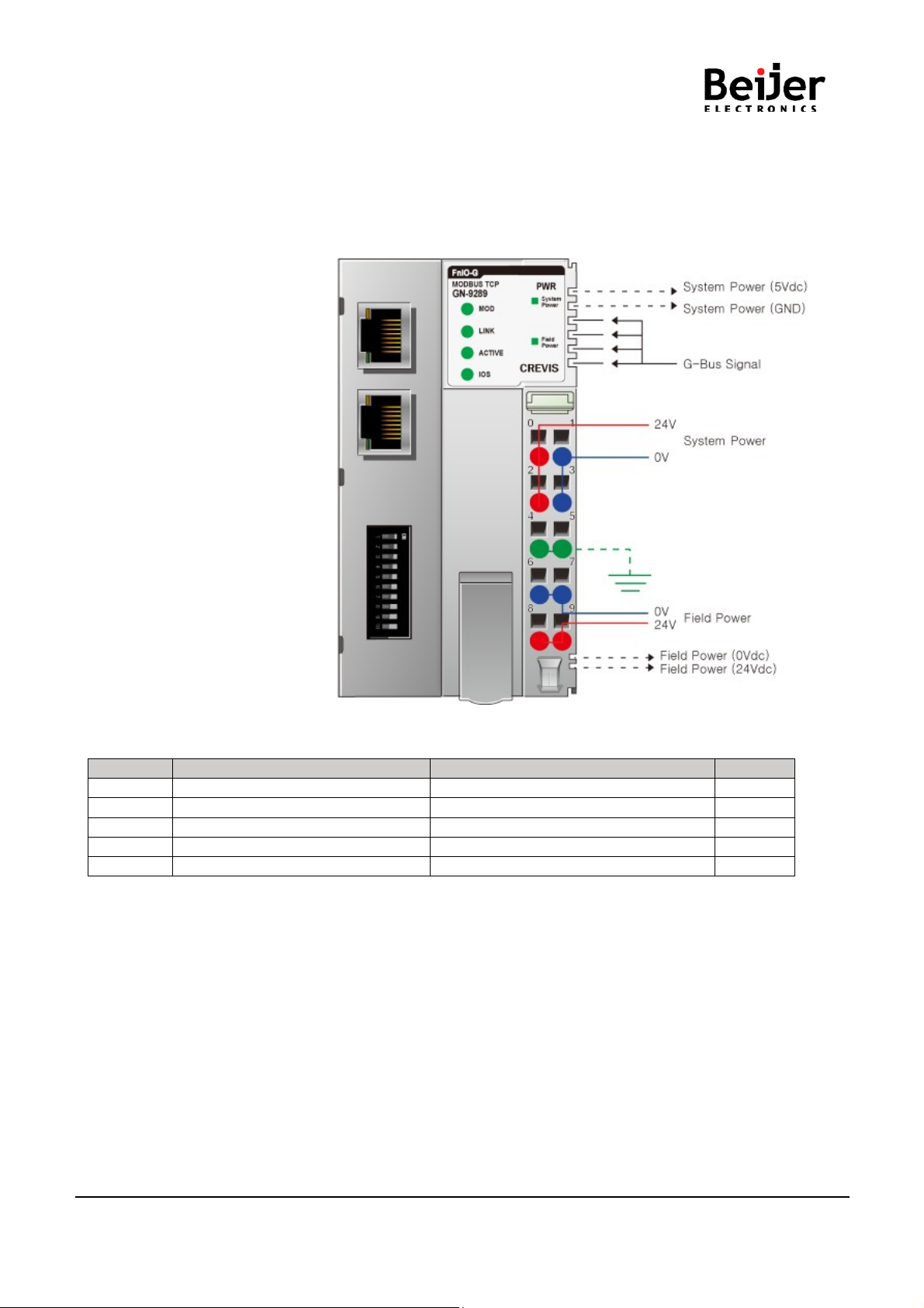
4.4 How to supply the power correctly.............................................................................................................16
5.
ConvenienceFunction.................................................................................................................................. 17
5.1.
Web Server....................................................................................................................................................17
5.2 IAP Functionality............................................................................................................................................. 19
6.
GN-9289Communication Interface............................................................................................................. 21
6.1 RJ-45 Socket .................................................................................................................................................21
6.2 Dip Switch (TBD)...........................................................................................................................................21
6.3 RS232 Port for MODBUS/RTU,Touch Panel or IOGuide...........................................................................22
6.4. MODBUS/TCPIP – Address Setup............................................................................................................ 23
6.4.1
IP-Address Setup using BOOTP/DHCPSever.................................................................................23
6.4.2
IP-Address Setup using DIPswitch (Manual function)..................................................................24
7.
I/O Process Image Map ................................................................................................................................28
7.1.
MODBUSInterface Register/Bit Map...........................................................................................................29

GN-9289 User Manual
Page 4 of (70)
G-series GN-9289 Modbus TCP_UDP Rev. 1.01.docx
7.2.
Example of Input Process Image (Input Register) Map.............................................................................30
7.3.
Example of Output Process Image (Output Register) Map.......................................................................31
8.
MODBUS TCP/ UDPINTERFACE................................................................................................................. 32
8.1.
MODBUS TCP/UDP Protocol.......................................................................................................................32
8.1.1
Comparison of MODBUS TCP/ UDP And MODUB/RTU.................................................................. 32
8.1.2
MODBUS TCP/ UDP MBAP Header..................................................................................................33
8.2.
Supported MODBUSFunction Codes .........................................................................................................34
8.2.1
1 (0x01) Read Coils...........................................................................................................................34
8.2.2
2 (0x02) Read Discrete Inputs..........................................................................................................35
8.2.3
3 (0x03) Read Holding Registers......................................................................................................36
8.2.4
4 (0x04) Read Input Registers..........................................................................................................37
8.2.5
5 (0x05) Write Single Coil .................................................................................................................37
8.2.6
6 (0x06) Write Single Register..........................................................................................................38
8.2.7
8 (0x08) Diagnostics..........................................................................................................................39
8.2.8
15 (0x0F) Write Multiple Coils ..........................................................................................................41
8.2.9
16 (0x10) Write Multiple Registers................................................................................................... 42
8.2.10 23 (0x17) Read/Write Multiple Registers .........................................................................................43
8.2.11 Error Response.................................................................................................................................. 44
8.3.
MODBUSSpecial Register Map ..................................................................................................................45
8.3.1.
AdapterIdentification SpecialRegister (0x1000, 4096)..................................................................45
8.3.2.
AdapterWatchdog Time, other Time SpecialRegister (0x1020, 4128)..........................................46
8.3.3.
AdapterTCP/IPSpecial Register(0x1040, 4160).............................................................................46
8.3.4.
AdapterInformation SpecialRegister (0x1100,4352).....................................................................47
8.3.5.
Expansion Slot Information Special Register (0x2000, 8192).......................................................48
8.4. Supported MODBUSFunction Codes..........................................................................................................50
9.
Object models ...............................................................................................................................................51
9.1. Supported Objects........................................................................................................................................51
9.2. Identity Object............................................................................................................................................... 52
9.2.1. Common Services.............................................................................................................................52

GN-9289 User Manual
Page 5 of (70)
G-series GN-9289 Modbus TCP_UDP Rev. 1.01.docx
9.2.2. Class Attributes.................................................................................................................................52
9.2.3. Instance Attributes............................................................................................................................53
9.3. Message Router Object.................................................................................................................................54
9.3.1 Common Services..............................................................................................................................54
9.3.2 Class Attributes .................................................................................................................................54
9.3.3 Instance Attributes.............................................................................................................................54
9.4. Assembly Object............................................................................................................................................ 55
9.4.1 Common Services..............................................................................................................................55
9.4.2 Class Attributes .................................................................................................................................55
9.4.3 Class Attributes .................................................................................................................................55
9.5 Connection Manager Object...........................................................................................................................55
9.5.1 Class Attributes, Instance Attribute..................................................................................................55
9.6 Port Object.......................................................................................................................................................56
9.6.1 Common Services.............................................................................................................................56
9.6.2 Class Attributes .................................................................................................................................56
9.6.3 Instance Attributes.............................................................................................................................56
9.7 TCP/IP Object ..................................................................................................................................................57
9.7.1.
Common Services.............................................................................................................................57
9.7.2
Class Attributes.................................................................................................................................57
9.7.3.1
Status Instance Attributes................................................................................................................58
9.8. Ethernet Link Object.....................................................................................................................................59
9.8.1.
Common Services.............................................................................................................................59
9.8.2
Class Attributes.................................................................................................................................59
9.9. G-Bus Manager Object.................................................................................................................................61
9.9.1
Common Services.............................................................................................................................61
9.9.2
Class Attributes.................................................................................................................................61
9.10 Expansion Slot Object.................................................................................................................................. 63
9.10.1 Common Services.............................................................................................................................63
9.10.2
Class Attributes.................................................................................................................................63
9.10.3
Instance Attributes............................................................................................................................63
10.
Trouble Shooting................................................................................................................................ 66
10.1. How to diagnose by LED indicator.............................................................................................................66

GN-9289 User Manual
Page 6 of (70)
G-series GN-9289 Modbus TCP_UDP Rev. 1.01.docx
1.
Important Notes
Solid state equipmenthas operational characteristics differingfrom those of electromechanicalequipment.
Safety Guidelinesfor the Application,Installationand Maintenanceof SolidState Controlsdescribes some
importantdifferencesbetweensolid state equipmentand hard-wired electromechanicaldevices.
Because of this difference, and also because of the wide variety of uses for solid state equipment,all
persons responsiblefor applyingthis equipmentmust satisfy themselvesthat each intended applicationof
this equipmentis acceptable.
In no event will CREVIS be responsible or liablefor indirect or consequentialdamagesresultingfrom the use
or applicationof this equipment.
The examplesand diagramsin this manualare includedsolely for illustrativepurposes. Because of the
manyvariables and requirements associated with any particular installation,CREVIS cannot assume
responsibilityor liabilityfor actual use based on the examples and diagrams.
If you don't follow the directions, it could causea personalinjury, damageto the equipmentor
explosion
Do not assemble the products and wire with power appliedto the system. Else it may cause an electric
arc, which can result into unexpectedand potentially dangerousaction by field devices. Arching is
explosion risk in hazardouslocations. Be sure that the area is non-hazardousor remove system power
appropriately before assembling or wiring the modules.
Do not touch any terminal blocks or IO moduleswhen system is running.Else it may cause the unit
to
an electric shock or malfunction.
Keep away from the strange metallicmaterialsnot relatedto the unit and wiring works should be
controlledby the electric expert engineer.Else it may cause the unitto a fire, electric shock or
malfunction
If you disobeythe instructions,there may be possibilityof personalinjury, damage to equipment
or explosion. Pleasefollow below Instructions.
•Check the rated voltage and terminalarray before wiring.Avoid the circumstances over 50℃of
temperature.Avoid placing it directly in the sunlight.
•Avoid the place undercircumstances over 85% of humidity.
•Do not place Modulesnear by the inflammable material.Else it may cause a fire.
•Do not permit any vibration approaching it directly.
•Go throughmodule specification carefully, ensure inputs,output connectionsare made with the
specifications. Use standard cables for wiring.
•Use Product underpollutiondegree 2 environment.
Warning!
Caution!

GN-9289 User Manual
Page 7 of (70)
G-series GN-9289 Modbus TCP_UDP Rev. 1.01.docx
1.1.
SafetyInstruction
1.1.1.
Symbols
Identifiesinformationabout practices or circumstances that can cause an
explosion in a hazardousenvironment,which may lead to personalinjuryor
death propertydamage,or economic loss
Identifiesinformationthat is critical for successful applicationand understandingof the
product
Identifiesinformationabout practices or circumstances that can lead to personal
injury, property damage,or economicloss.
Attentionshelp you to identitya hazard, avoid a hazard, and recognize the
consequences
1.1.2.
Safety Notes
The modulesare equippedwith electroniccomponentsthat may be destroyed by
electrostaticdischarge.When handlingthe modules, ensure that the environment (persons,
workplace and packing) is well grounded.Avoid touchingconductive components,G-BUS
Pin.

GN-9289 User Manual
Page 8 of (70)
G-series GN-9289 Modbus TCP_UDP Rev. 1.01.docx
2.
Specification
2.1.
The Interface
2.1.1 GN-9289 (MODBUS TCP)
System power and Field power must be suppliedseparately.
Pin No.
SignalDescription
SignalDescription
Pin No.
0
System Power, 24V
System Power, Ground
1
2
System Power, 24V
System Power, Ground
3
4
F.G
F.G
5
6
Field Power, Ground
Field Power, Ground
7
8
FieldPower, 24V
Field Power, 24V
9

GN-9289 User Manual
Page 9 of (70)
G-series GN-9289 Modbus TCP_UDP Rev. 1.01.docx
2.2.
General Specification
2.2.1.
GeneralSpecification
Generalspecification
System Power
Supplyvoltage: 24Vdc nominal
Supplyvoltagerange: 15~32Vdc
Protection: Output current limit (Min.1.5A)
Reverse polarityprotection
Power Dissipation
70mAtypical @ 24Vdc
Current for I/O Module
1.5A @ 5Vdc (When using in ‘60℃~ 70℃’temperature environment,
the power dissipationis limited to 0.8A.)
Isolation
System power to internal logic : Non-isolation
System power I/O driver : Isolation
FieldPower
Supplyvoltage : 24Vdc typical (Max. 32Vdc)
* Field Power Range is differentdependingon IO Module series.
Refer to IO Module`sSpecification.
Max. Current Field Power Contact
DC 10A Max
Weight
162g
Module Size
54mm x 99mm x 70mm
Environmental specification
OperatingTemperature
60℃~ 70℃: Power dissipationis limitedto 0.8A.
-40℃~60℃: 1.5Afull loadis allowed.
UL Temperature
-20℃~60℃
StorageTemperature
-40℃~85℃
Relative Humidity
5% ~ 90%non-condensing
Mounting
DIN rail
* When using Ethernet/IP only, tcp timeout connection time value should be ‘0’. ‘0’ value means tcp
connection time out is disabled. Refer to ‘Adapter TCP/IP Special Register (0x1040, 4160)’ at section ‘
3.3.3’
** When using in ‘60℃~ 70℃’ temperatureenvironment,the power dissipation is limited to 0.8A.

GN-9289 User Manual
Page 10 of (70)
G-series GN-9289 Modbus TCP_UDP Rev. 1.01.docx
2.2.2 Interface Specification
Items
Specification
Input Specification
AdapterType Slave node(MODBUS/TCP,MODBUS/UDP Server)
Protocol
MODBUS/TCP,MODBUS/UDP,HTTP,DHCP,10TCPConnections
Sub-Protocol
*Ethernet/IP
Max. Expansion Module
63 slots
Max. DataSize(Input+Output)
Max 128bytes each slot
Max LengthBus Line
Up to 100m from Ethernet Hub/Switch with twisted CAT5 UTP/STP
Max. Nodes
LimitedbyEthernetSpecification.
Baud Rate
10/100Mbps,Auto-negotiation,Fullduplex
InterfaceConnector
RJ-45 socket * 2pcs
IP-AddressSetup
Via DHCP/BOOTP or IOGuide(CrevisSoftware)
IP-Address Range xxx.xxx.xxx.1 ~253 (User area)
xxx.xxx.xxx.254 ~ 255 (Reserved for IAP Function)
SerialPort
RS232 for MODBUS/RTU, Touch Panelor IOGuide
SerialConfiguration(RS232)
Node
:
1 (Fixed)
Baud Rate : 115200 (Fixed)
Data bit : 8 (Fixed)
Parity bit : No parity (Fixed)
Stop bit : 1 (Fixed)
Indicator
6 LEDs
1 Green/Red,ModuleStatus (MOD)
1 Green, Physical Connection(LINK)
1 Green, Exchange Data/TrafficPresent (ACTIVE)
1 Green/Red, Expansion I/O ModuleStatsus (IOS)
1 Green, System Power Status
1 Green, Field Power Status
2 LEDs (each RJ45 Connector)
1 Yellow, Link/Active
1 Green, Not used
Module Location
Starter moduleleft side of G-Series system
Field Power Detection
About14Vdc

GN-9289 User Manual
Page 11 of (70)
G-series GN-9289 Modbus TCP_UDP Rev. 1.01.docx
2.3. GN-9289 LED Indicator
LED No.
LED Function / Description
LED Color
MOD
Module Status
Green/Red
LINK
Physical Connection
Green
ACTIVE
Exchange Data/TrafficPresent
Green
IOS
Extension Module Status
Green/Red
System Power
System Power Enable
Green
FieldPower
Field Power Enable
Green
2.3.1.
Module Status LED (MOD)
Status
LED
To indicate
NotPowered
OFF
Not power is suppliedto the unit.
Device Operational
Green
The unitis operatingin normalcondition.
Device in Standby FlashingGreen
The device needs commissioning due to configuration missing,
incomplete or incorrect.
MODBUS Error
Green/Red
Toggle MODBUS error such as watchdog error, etc.
MinorFault FlashingRed
Recoverable Fault.
- EEPROM checksum fault.
Unrecoverable
Fault Red
The device has an unrecoverablefault.
- Memoryerror or CPU watchdog error.
2.3.2.
Physical Connection LED(LINK)
Status
LED
To indicate
Not Powered or Not Linked OFF Device may not be powered
Adapterphysical connected
Green
AdapterEthernetControllerphysicallyconnected

GN-9289 User Manual
Page 12 of (70)
G-series GN-9289 Modbus TCP_UDP Rev. 1.01.docx
2.3.3
Exchange Data/Traffic Present LED(ACTIVE)
Status
LED
To indicate
NotPowered
OFF
Device is idleor maynot be powered.
Adapterexchange data
Flashing
Green
Adapter(slave)exchange data/Trafficpresent.
About10msec flashing.
2.3.4
Extension Module Status LED(IOS)
Status
LED
To indicate
NotPowered
OFF
Device may not be powered.
No Expansion Module
FlashingRed
Adapterhas no expansion module
InternalBus Connection,
Run Exchanging I/O
Green ExchangingI/O data.
Expansion Configuration
Failed
Red
One or more expansion moduleoccurred in fault state.
- Detected invalid expansion moduleID.
- Overflowed Input/OutputSize
- Too manyexpansion module
- Initialization failure
- Communicationfailure.
- Changedexpansionmoduleconfiguration.
- Mismatch vendor code between adapterand expansion
module.
2.3.5
Field Power Status LED
Status
LED
To indicate
No field, System power
OFF
Not supplied24Vdc field power, 5Vdc system power.
Supplied
field, System power
Green Supplied24Vdc field power, 5Vdc system power.

GN-9289 User Manual
Page 13 of (70)
G-series GN-9289 Modbus TCP_UDP Rev. 1.01.docx
3.
Dimension
3.1 GN-9289
(mm)

GN-9289 User Manual
Page 14 of (70)
G-series GN-9289 Modbus TCP_UDP Rev. 1.01.docx
4.
Mechanical Set Up
4.1 Total Expansion
The number of the module assembly that can be connected is 63 so the maximum length is 426mm
Exception GN-9289 is excepted to calculate maximum length because that is doublewidth module.
4.2. Plugging and Removal of the Components.
As above figure in order to safeguard the FnIO module from jamming, it should be fixed onto the DIN rail
with locking level. To do so, fold on the upperof the locking lever.
Topull out the FnIO module,unfoldthe locking lever as belowfigure.
Before work is done on the components, the voltage supply must be turnedoff.

GN-9289 User Manual
Page 15 of (70)
G-series GN-9289 Modbus TCP_UDP Rev. 1.01.docx
4.3 Module mounting

GN-9289 User Manual
Page 16 of (70)
G-series GN-9289 Modbus TCP_UDP Rev. 1.01.docx
4.4 How to supply the power correctly
- Refer the pin map of power RTB before wiring.
- Current capacity marginshould be considered when you supply the power.
- Supplyvoltage 24Vdc which is recommendedvoltage level.
- System and Fieldpower must be suppliedseparately as the picture above.
※If the power is suppliedto each System and Field power from same power source, it would be vulnerable
to power noise.

GN-9289 User Manual
Page 17 of (70)
G-series GN-9289 Modbus TCP_UDP Rev. 1.01.docx
5.
Convenience Function
5.1.
Web Server
NetworkAdapter

GN-9289 User Manual
Page 18 of (70)
G-series GN-9289 Modbus TCP_UDP Rev. 1.01.docx
ExpansionModule

GN-9289 User Manual
Page 19 of (70)
G-series GN-9289 Modbus TCP_UDP Rev. 1.01.docx
5.2 IAP Functionality
After setting up the dip switch as 254 or 255, Power off and on in orderto start the IAP mode.
(254=FixedIP Address (192.168.0.100) / 255=Last used IPAddress)
After Login the Web Browser connecting
(User ID: beijer, Password: beijer)
Toupdate the binaryfile.

GN-9289 User Manual
Page 20 of (70)
G-series GN-9289 Modbus TCP_UDP Rev. 1.01.docx
Has been updated.Please reboot the adapter.
Table of contents
Other BeiJer Adapter manuals