BeiJer HVAC H2 Operation manual


User Guide Revision 1.12
2
IP55 Quick Start Up Guide
Supply Voltage
Keypad Operation can be found in
section 5.5
Run / Stop 10K Pot
HVAC Display
(Status, Diagnostics, and Programming)
Motor Cable
For correct cable size, see Technical
Data in section 13.4.
Observe the maximum permissible
motor cable length.
For Motor cable lengths > 50 metres, an
output filter is recommended.
Use a screened (shielded cable). The
shield should be bonded to earth at
both ends.
Motor Connection
Check for Star or Delta connection
according to the motor voltage rating in
section 4.5.
Motor Nameplate Details
Motor Rated Voltage: P1-07
Motor Rated Current: P1-08
Motor Rated Frequency: P1-09
Motor Rated Speed (Optional): P1-10
Fuses or MCB
Check Drive
Rating info in
section 13.4
AC Supply Connection
200 –240 Volts + / - 10%
380 –380 Volts + / - 10%
Check Drive Input Voltage
information in section 13.2
PE L1 L2 L3
Control Terminal
Configuration based on factory settings
Mechanical Mounting
Information can be found in section 3.6.
Hardware Enable
Link the terminals as shown, optionally
through switch contacts to enable drive
operation
Close the switch to run (enable)
Open the switch to stop
RJ45
Connector

User Guide Revision 1.12
3
IP66 Quick Start Up Guide
HVAC Display
(Status, Diagnostics, and Programming)
Motor Cable Sizes
Check the rating information in
section 13.4.
Motor Connections
Check for Star or Delta connection
according to the motor voltage rating in
section 4.5.
Motor Nameplate Details
Motor Rated Voltage: P1-07
Motor Rated Current: P1-08
Motor Rated Frequency: P1-09
Motor Rated Speed (Optional): P1-10
Mechanical Mounting
Information can be found in section 3.5.
Control Terminal
Configuration based on factory settings
Hardware
Link the terminals as shown, optionally
through switch contacts to enable drive
operation
Close the switch to run (enable)
Open the switch to stop
Keypad Operation can be found in
section 5.5
Applies to Switched version only
In-built Isolator:
Mains Power On / Off
Fuses or MCB
Check Drive
Rating info in
section 13.4.
AC Supply Connection
200 –240 Volts + / - 10%: 1 / 3 Phase
380 –380 Volts + / - 10%: 3 Phase
Check Drive Input Voltage information
in section 13.2
PE L1 L2 L3
Run / Stop 10K Pot
RJ45
Connector

User Guide Revision 1.12
4
IP20 Quick Start Up Guide
AC Supply Connection Supply Voltage
3 Phase Units : Connect L1 L2 L3, PE 200 –240 Volts + / - 10%
1 Phase Units : Connect L1, L2, PE 380 –380 Volts + / - 10%
Fuses or MCB
oCheck the Drive Rating Information in section 13.4
Help Card
Display Information can be found in section 5.1
Keypad Operation can be found in section 5.1
IMPORTANT!
Hardware Enable
Link the terminals as shown, optionally through switch contacts to enable
drive operation
Control Terminals
Based on the factory default parameter settings
Run –Stop 10K Speed Pot
Close the switch to run (enable), open to stop
Motor Cable
oFor correct cable size in section 13.4
oObserve the maximum permissible motor cable length
oFor Motor cable lengths > 50 metres, an output filter is
recommended
oUse a screened (shielded cable)
Motor Connection
oCheck for Star or Delta connection according to the motor
voltage rating in section 4.5.
oMotor Nameplate Details
oMotor Rated Voltage : P1-07
oMotor Rated Current : P1-08
oMotor Rated Frequency : P1-09
oMotor Rated Speed (Optional) : P1-10
Fuses or MCB
RJ45
Connector

User Guide Revision 1.12
5
Declaration of Conformity:
The Manufacturer hereby states that the HVAC Inverter H2 product range conforms to the relevant safety provisions of the Low Voltage
Directive 2006/95/EC and the EMC Directive 2004/108/EC and has been designed and manufactured in accordance with the following
harmonised European standards:
EN 61800-5-1: 2003
Adjustable speed electrical power drive systems. Safety requirements. Electrical, thermal and energy.
EN 61800-3 2nd Ed: 2004
Adjustable speed electrical power drive systems. EMC requirements and specific test methods
EN 55011: 2007
Limits and Methods of measurement of radio disturbance characteristics of industrial, scientific and
medical (ISM) radio-frequency equipment (EMC)
EN60529 : 1992
Specifications for degrees of protection provided by enclosures
STO Function
HVAC Inverter H2 incorporates a hardware STO (Safe Torque Off) Function, designed in accordance with the standards listed below.
Standard
Classification
Approval Status
IEC61608
SIL 2
Pending Certification
IEC 61800-5-2
Type 2
Pending Certification
IEC 62061
SIL 2
Pending Certification
ISO 13849
PL “d”
Pending Certification
Electromagnetic Compatibility
All drives are designed with high standards of EMC in mind. All versions suitable for operation on Single Phase 230 volt and Three Phase 400
volt supplies and intended for use within the European Union are fitted with an internal EMC filter. This EMC filter is designed to reduce the
conducted emissions back into the supply via the power cables for compliance with harmonised European standards.
It is the responsibility of the installer to ensure that the equipment or system into which the product is incorporated complies with the EMC
legislation of the country of use. Within the European Union, equipment into which this product is incorporated must comply with the EMC
Directive 2004/108/EC. When using a drive with an internal or optional external filter, compliance with the following EMC Categories, as
defined by EN61800-3:2004 can be achieved:
Drive Type / Rating
EMC Category
Cat C1
Cat C2
Cat C3
1 Phase, 230 Volt Input
BFI-H2
No additional filtering required
Use shielded motor cable
3 Phase, 230/400 Volt
Input
BFI-H2
Use External Filter
No additional filtering required
Use screened motor cable
Note
For motor cable lengths greater than 100m, an output dv / dt filter must be used, please refer to your local supplier for further
details
All rights reserved. No part of this User Guide may be reproduced or transmitted in any form or by any means, electrical or mechanical
including photocopying, recording or by any information storage or retrieval system without permission in writing from the publisher.
Beijer Electronics © 2012
All HVAC units carry a 2 year warranty against manufacturing defects from the date of manufacture. The manufacturer accepts no liability for
any damage caused during or resulting from transport, receipt of delivery, installation or commissioning. The manufacturer also accepts no
liability for damage or consequences resulting from inappropriate, negligent or incorrect installation, incorrect adjustment of the operating
parameters of the drive, incorrect matching of the drive to the motor, incorrect installation, unacceptable dust, moisture, corrosive
substances, excessive vibration or ambient temperatures outside of the design specification.
The local distributor may offer different terms and conditions at their discretion, and in all cases concerning warranty, the local distributor
should be contacted first.
The contents of this User Guide are believed to be correct at the time of printing. In the interest of a commitment to a policy of continuous
improvement, the manufacturer reserves the right to change the specification of the product or its performance or the contents of the User
Guide without notice.
This User Guide is for use with version 1.10 Firmware.
User Guide Revision 1.12
The Manufacturer adopts a policy of continuous improvement and whilst every effort has been made to provide accurate and up to date
information, the information contained in this User Guide should be used for guidance purposes only and does not form the part of any
contract.

User Guide Revision 1.12
6
1. Introduction................................................................................................................................ 8
1.1. Important safety information ............................................................................................................................................. 8
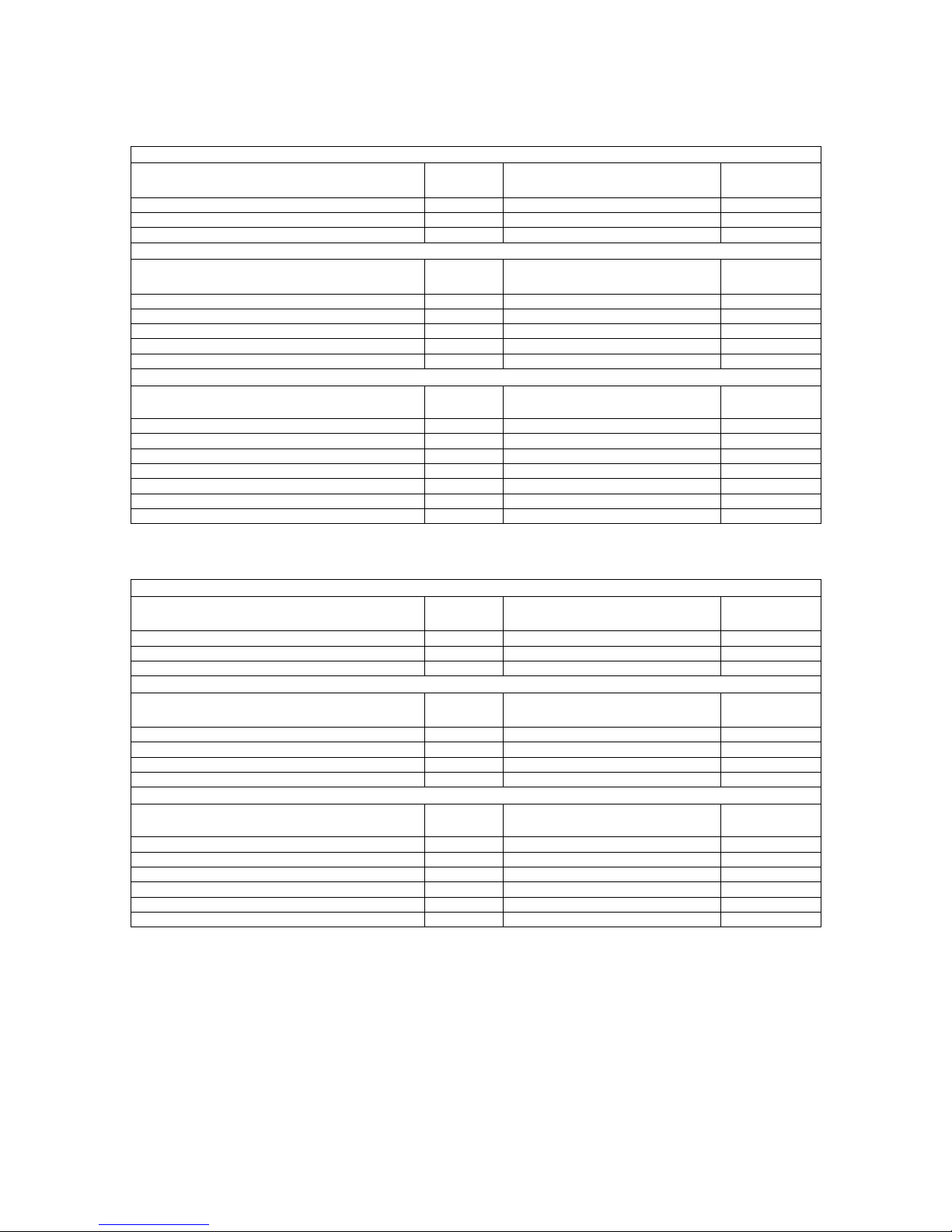
2. General Information and Ratings ................................................................................................. 9
2.1. Drive model numbers.......................................................................................................................................................... 9
2.2. Identifying the Drive by Model Number ........................................................................................................................... 10
3. Mechanical Installation ............................................................................................................. 11
3.1. General.............................................................................................................................................................................. 11
3.2. Before Installation............................................................................................................................................................. 11
3.3. UL Compliant Installation.................................................................................................................................................. 11
3.4. Mechanical dimensions and Mounting –IP20 Units......................................................................................................... 11
3.5. Mechanical dimensions and mounting –IP66 Units ......................................................................................................... 12
3.6. Mechanical dimensions and mounting –IP55 .................................................................................................................. 12
3.7. Mechanical dimensions and mounting –IP40 Units ......................................................................................................... 13
3.8. Guidelines for Enclosure mounting (IP20 Units) ............................................................................................................... 14
3.9. Guidelines for mounting IP55, and IP66 Units .................................................................................................................. 14
3.10. Guidelines for mounting IP40 Units .................................................................................................................................. 15
3.11. Removing the Terminal Cover........................................................................................................................................... 16
3.12. Gland Plate and Lock Off................................................................................................................................................... 19
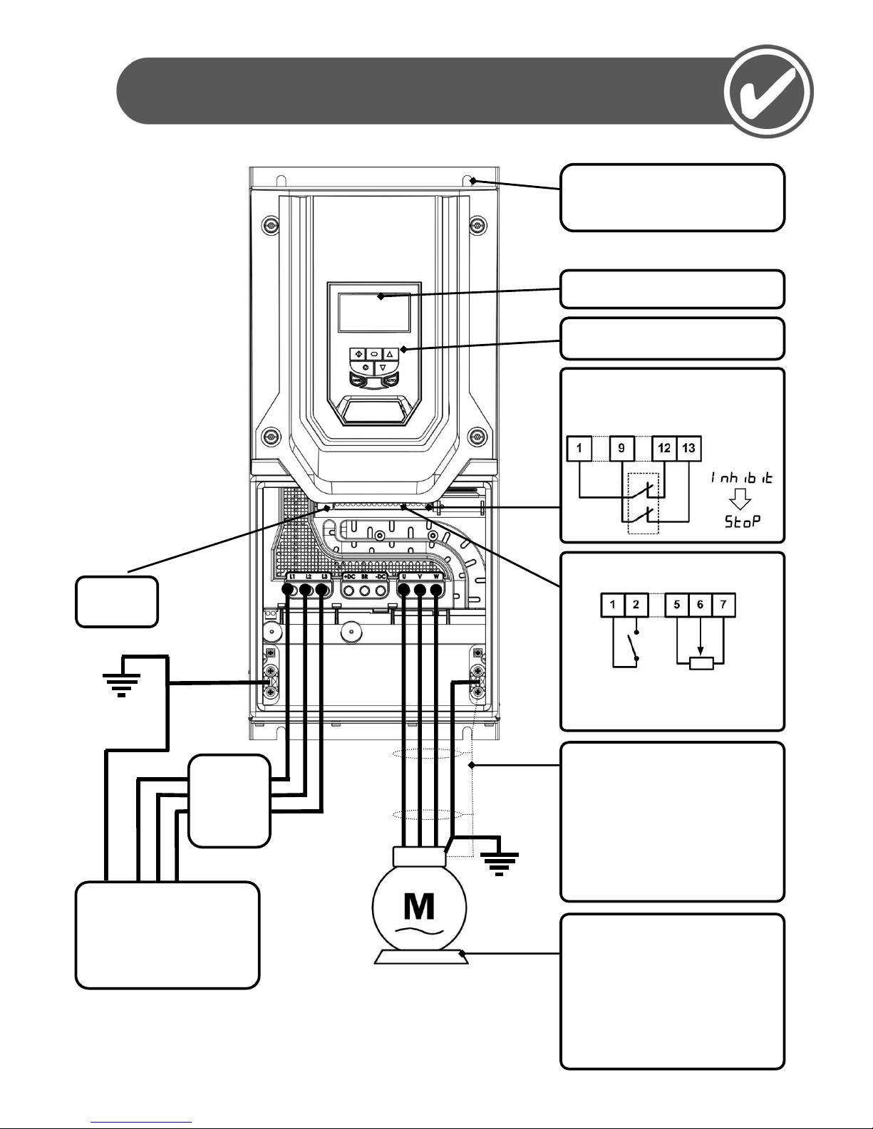
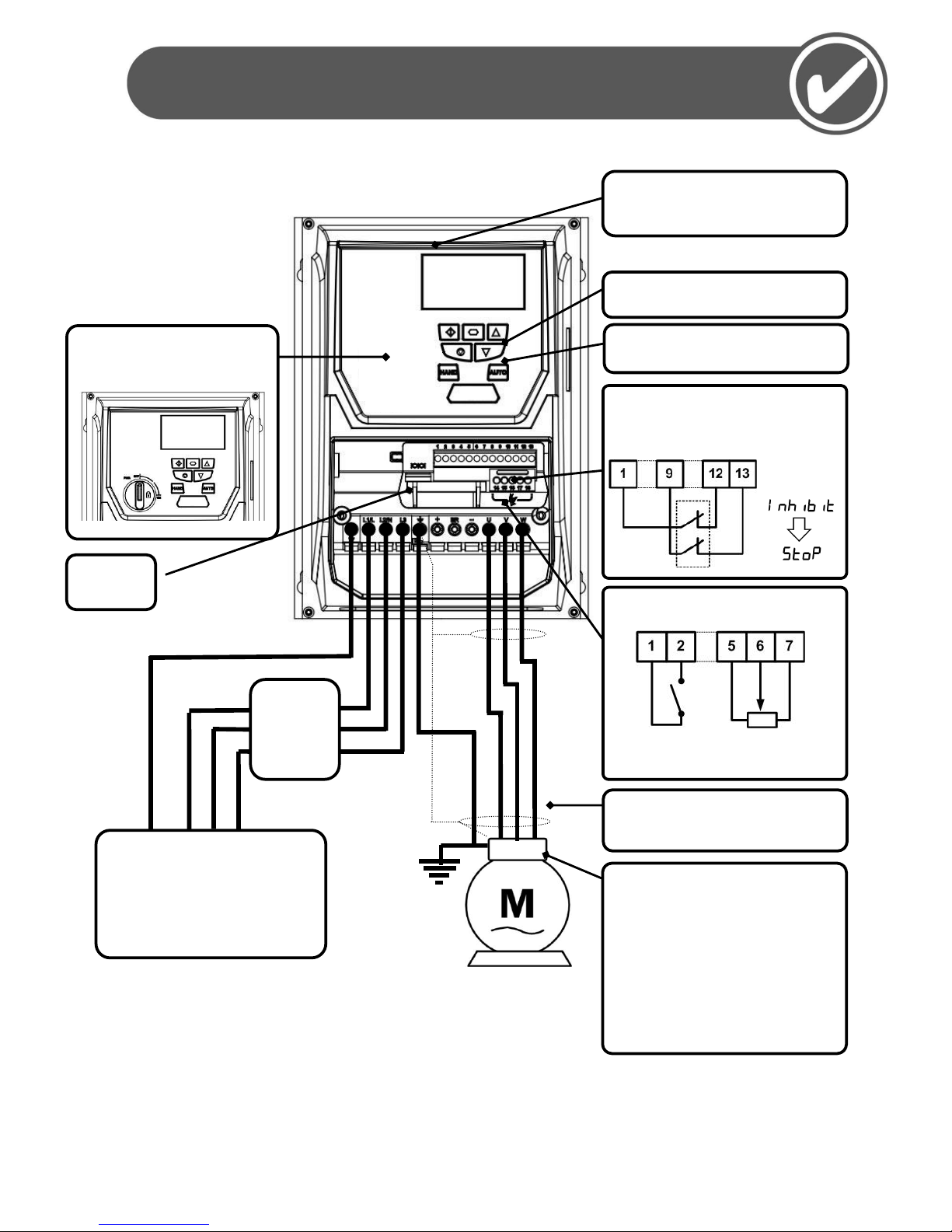
4. Electrical Installation ................................................................................................................. 20
4.1. Grounding the Drive.......................................................................................................................................................... 20
4.2. Wiring Precautions............................................................................................................................................................ 21
4.3. Incoming Power Connection ............................................................................................................................................. 21
4.4. Drive and Motor Connection ............................................................................................................................................ 21
4.5. Motor Terminal Box Connections ..................................................................................................................................... 22
4.6. Motor Thermistor Connection .......................................................................................................................................... 22
4.7. Control Terminal Wiring.................................................................................................................................................... 23
4.8. Connection Diagram ......................................................................................................................................................... 23
5. Managing the Keypad................................................................................................................ 24
5.1. Keypad Layout and Function –Standard LED Keypad (IP20 Drives) ................................................................................. 24
5.2. Changing Parameters –Standard LED Keypad (IP20 Drives)............................................................................................. 24
5.3. Advanced Keypad Operation Short Cuts –Standard LED Keypad (IP20 Drives) ............................................................... 25
5.4. Drive Operating Displays –Standard LED Keypad (IP20 Drives) ....................................................................................... 25
5.5. Keypad Layout and Function –Standard OLED Keypad (IP55 and IP66 Drives)................................................................ 25
5.6. Drive Operating Displays –Standard OLED Keypad (IP55 and IP66 Drives)...................................................................... 26
5.7. Accessing and Changing Parameter Values –Standard OLED Keypad (IP55 and IP66 Drives) ......................................... 26
5.8. Resetting Parameters to Factory Default Settings –Standard OLED Keypad (IP55 and IP66 Drives) ............................... 27
5.9. Resetting Parameters to User Default Settings –Standard OLED Keypad (IP55 and IP66 Drives) ................................... 27
5.10. Changing the Language on the OLED Display –Standard OLED Keypad (IP55 and IP66 Drives) ...................................... 28
5.11. Selecting between Hand and Auto Control –Standard OLED Keypad (IP55 and IP66 Drives).......................................... 28
6. Commissioning.......................................................................................................................... 29
6.1. General.............................................................................................................................................................................. 29
7. HVAC Specific Feature Setup (Menu 8)....................................................................................... 30
7.1. Pump Staging –DOL Cascade............................................................................................................................................ 30
7.2. Pump Staging –Multiple Drive Cascade ........................................................................................................................... 31
7.3. Maintenance Interval Set-up and Reset............................................................................................................................ 32
7.4. Load Profile Monitoring Function ..................................................................................................................................... 33
7.5. Pump Clean Function ........................................................................................................................................................ 34
7.6. Pump Stir Function............................................................................................................................................................ 35
7.7. Bypass Control Function ................................................................................................................................................... 36
7.8. Fire Mode Function ........................................................................................................................................................... 38
7.9. Motor Pre-Heat Function and DC Injection ...................................................................................................................... 40
8. PID Control Applications............................................................................................................ 42
8.1. Overview ........................................................................................................................................................................... 42
8.2. PID Function Set-up .......................................................................................................................................................... 42
8.3. Application Example.......................................................................................................................................................... 45
8.4. PID Pipe Prime (Fill) Mode with Pipe Break Detection. .................................................................................................... 46
9. Parameters ............................................................................................................................... 47
9.1. Parameter Set Overview ................................................................................................................................................... 47
9.2. Parameter Group 1 –Basic Parameters............................................................................................................................ 47
10. Digital Input Functions .............................................................................................................. 49

User Guide Revision 1.12
7
10.1. Digital Input Configuration Parameter P1-13 ................................................................................................................... 49
11. Extended Parameters ................................................................................................................ 50
11.1. Parameter Group 2 - Extended parameters...................................................................................................................... 50
11.2. Parameter Group 3 –PID Control ..................................................................................................................................... 54
11.3. Parameter Group 4 –High Performance Motor Control .................................................................................................. 55
11.4. Parameter Group 5 –Communication Parameters .......................................................................................................... 55
11.5. Parameter Group 6 –Advance Feature configuration ...................................................................................................... 56
11.6. Parameter Group 7 –Reserved (not available)................................................................................................................. 57
11.7. Parameter Group 8 –HVAC Function Specific Parameters............................................................................................... 57
11.8. Parameter Group 9 –Advance drive control logic configuration ..................................................................................... 59
11.9. Parameter Group 0 –Monitoring Parameters (Read Only) .............................................................................................. 60
12. Serial communications .............................................................................................................. 63
12.1. RS-485 communications.................................................................................................................................................... 63
12.2. Modbus RTU Communications ......................................................................................................................................... 63
13. Technical Data........................................................................................................................... 65
13.1. Environmental................................................................................................................................................................... 65
13.2. Input voltage ranges ......................................................................................................................................................... 65
13.3. Maximum supply ratings for UL compliance..................................................................................................................... 65
13.4. Output Power and Current ratings ................................................................................................................................... 65
13.5. Additional Information for UL Approved Installations...................................................................................................... 67
14. Parameter Change Tables .......................................................................................................... 68
15. Troubleshooting........................................................................................................................ 70
15.1. Fault messages.................................................................................................................................................................. 70

User Guide Revision 1.12
8
1. Introduction
1.1. Important safety information
Please read the IMPORTANT SAFETY INFORMATION below, and all Warning and Caution information elsewhere.
Danger : Indicates a risk of electric shock, which, if not
avoided, could result in damage to the equipment and
possible injury or death.
Danger : Indicates a potentially hazardous situation
other than electrical, which if not avoided, could result
in damage to property.
This variable speed drive product is intended for professional incorporation into complete equipment or systems as part of a fixed
installation. If installed incorrectly it may present a safety hazard. The drive uses high voltages and currents, carries a high level of
stored electrical energy, and is used to control mechanical plant that may cause injury. Close attention is required to system design
and electrical installation to avoid hazards in either normal operation or in the event of equipment malfunction. Only qualified
electricians are allowed to install and maintain this product.
System design, installation, commissioning and maintenance must be carried out only by personnel who have the necessary
training and experience. They must carefully read this safety information and the instructions in this Guide and follow all
information regarding transport, storage, installation and use of the drive, including the specified environmental limitations.
Do not perform any flash test or voltage withstand test on the drive. Any electrical measurements required should be carried out
with the drive disconnected.
Electric shock hazard! Disconnect and ISOLATE the drive before attempting any work on it. High voltages are present at the
terminals and within the drive for up to 10 minutes after disconnection of the electrical supply. Always ensure by using a suitable
multimeter that no voltage is present on any drive power terminals prior to commencing any work.
Where supply to the drive is through a plug and socket connector, do not disconnect until 10 minutes have elapsed after turning off
the supply.
Ensure correct earthing connections. The earth cable must be sufficient to carry the maximum supply fault current which normally
will be limited by the fuses or MCB. Suitably rated fuses or MCB should be fitted in the mains supply to the drive, according to any
local legislation or codes.
Do not carry out any work on the drive control cables whilst power is applied to the drive or to the external control circuits.
Within the European Union, all machinery in which this product is used must comply with Directive 98/37/EC, Safety of Machinery.
In particular, the machine manufacturer is responsible for providing a main switch and ensuring the electrical equipment complies
with EN60204-1.
The level of integrity offered by the drive control input functions –for example stop/start, forward/reverse and maximum speed, is
not sufficient for use in safety-critical applications without independent channels of protection. All applications where malfunction
could cause injury or loss of life must be subject to a risk assessment and further protection provided where needed.
The driven motor can start at power up if the enable input signal is present.
The STOP function does not remove potentially lethal high voltages. ISOLATE the drive and wait 10 minutes before starting any
work on it. Never carry out any work on the Drive, Motor or Motor cable whilst the input power is still applied.
The drive can be programmed to operate the driven motor at speeds above or below the speed achieved when connecting the
motor directly to the mains supply. Obtain confirmation from the manufacturers of the motor and the driven machine about
suitability for operation over the intended speed range prior to machine start up.
Do not activate the automatic fault reset function on any systems whereby this may cause a potentially dangerous situation.
The drive has an Ingress Protection rating of IP55, and are intended for indoor use only
When mounting the drive, ensure that sufficient cooling is provided. Do not carry out drilling operations with the drive in place,
dust and swarf from drilling may lead to damage.
The entry of conductive or flammable foreign bodies should be prevented. Flammable material should not be placed close to the
drive
Relative humidity must be less than 95% (non-condensing).
Ensure that the supply voltage, frequency and no. of phases (1 or 3 phase) correspond to the rating of the drive as delivered.
Never connect the mains power supply to the Output terminals U, V, W.
Do not install any type of automatic switchgear between the drive and the motor
Wherever control cabling is close to power cabling, maintain a minimum separation of 100 mm and arrange crossings at 90 degrees
Ensure that all terminals are tightened to the appropriate torque setting
Do not attempt to carry out any repair of the drive. In the case of suspected fault or malfunction, contact your local Sales Partner
for further assistance.

User Guide Revision 1.12
9
2. General Information and Ratings
2.1. Drive model numbers
2.1.1. IP20 Enclosed Units
2.1.2. IP66 Enclosed Units
200-240V ±10% - 1 Phase Input
kW Model with Filter
kW
Output
Current (A)
Frame
Size
BFI-H2-22-0043-1KF12-xx
0.75
4.3
2
BFI-H2-22-0070-1KF12-xx
1.5
7
2
BFI-H2-22-0105-1KF12-xx
2.2
10.5
2
200-240V ±10% - 3 Phase Input
kW Model Number with Filter
kW
Output
Current (A)
Frame
Size
BFI-H2-22-0043-3KF12-xx
0.75
4.3
2
BFI-H2-22-0070-3KF12-xx
1.5
7
2
BFI-H2-22-0105-3KF12-xx
2.2
10.5
2
BFI-H2-32-0018-3KF12-xx
4.0
18
3
BFI-H2-32-0240-3KF12-xx
5.5
24
3
380-480V ±10% - 3 Phase Input
kW Model Number with Filter
kW
Output
Current (A)
Frame
Size
BFI-H2-24-0022-3KF12-xx
0.75
2.2
2
BFI-H2-24-0041-3KF12-xx
1.5
4.1
2
BFI-H2-24-0058-3KF12-xx
2.2
5.8
2
BFI-H2-24-0095-3KF12-xx
4
9.5
2
BFI-H2-34-0140-3KF12-xx
5.5
14
3
BFI-H2-34-0180-3KF12-xx
7.5
18
3
BFI-H2-34-0240-3KF12-xx
11
24
3
200-240V ±10% - 1 Phase Input
kW Model with Filter
kW
Output
Current (A)
Frame
Size
BFI-H2-0043-22-1KF1X-xx / BFI-H2-22-0043-1KF1D-xx
0.75
4.3
2
BFI-H2-22-0070-1KF1X-xx / BFI-H2-22-0070-1KF1D-xx
1.5
7
2
BFI-H2-22-0105-1KF1X-xx / BFI-H2-22-0105-1KF1D-xx
2.2
10.5
2
200-240V ±10% - 3 Phase Input
kW Model Number with Filter
kW
Output
Current (A)
Frame
Size
BFI-H2-22-0043-3KF1X-xx / BFI-H2-22-0043-3KF1D-xx
0.75
4.3
2
BFI-H2-22-0070-3KF1X-xx / BFI-H2-22-0070-3KF1D-xx
1.5
7
2
BFI-H2-22-0105-3KF1X-xx / BFI-H2-22-0105-3KF1D-xx
2.2
10.5
2
BFI-H2-32-0180-3KF1X-xx / BFI-H2-32-0180-3KF1D-xx
4.0
18
3
380-480V ±10% - 3 Phase Input
kW Model Number with Filter
kW
Output
Current (A)
Frame
Size
BFI-H2-24-0022-3KF1X-xx / BFI-H2-24-0022-3KF1D-xx
0.75
2.2
2
BFI-H2-24-0041-3KF1X-xx / BFI-H2-24-0041-3KF1D-xx
1.5
4.1
2
BFI-H2-24-0058-3KF1X-xx / BFI-H2-24-0058-3KF1D-xx
2.2
5.8
2
BFI-H2-24-0095-3KF1X-xx / BFI-H2-24-0095-3KF1D-xx
4
9.5
2
BFI-H2-34-0140-3KF1X-xx / BFI-H2-34-0140-3KF1D-xx
5.5
14
3
BFI-H2-34-0180-3KF1X-xx / BFI-H2-34-0180-3KF1D-xx
7.5
18
3

User Guide Revision 1.12
10
2.1.3. IP55 Enclosed Units
2.1.4. IP40 Enclosed Units
2.2. Identifying the Drive by Model Number
Each drive can be identified by its model number, shown below. The model number is on the shipping label and the drive nameplate. The
model number includes the drive and factory fitted options.
BFI
-
H2
-
1
2
-
0023
-
1
B
1
2
Product Family
IP Rating
2 = IP20
X = IP66 Non Switched
Y = IP66 Switched
Generation
Dynamic Brake
Transistor
1 = Not Fitted
4 = Internal Transistor
Frame Size
1-8
Filter Type
0 = No Filter
A = Internal 400V EMC Filter
B = Internal 230V EMC Filter
Input Voltage
1 = 110 –115
2 = 200 –240
4 = 380 - 480
No. Of Input Phases
Current Rating
200-240V ±10% - 3 Phase Input
kW Model Number with Filter
kW
Output
Current (A)
Frame
Size
BFI-H2-44-0240-3KF1N-xx
5.5
24
4
BFI-H2-44-0300-3KF1N-xx
7.5
30
4
BFI-H2-44-0460-3KF1N-xx
11
46
4
BFI-H2-54-0610-3KF1N-xx
15
61
5
BFI-H2-54-0720-3KF1N-xx
18.5
72
5
BFI-H2-64-0900-3KF1N-xx
22
90
6
BFI-H2-64-1100-3KF1N-xx
30
110
6
BFI-H2-64-1500-3KF1N-xx
37
150
6
BFI-H2-64-1800-3KF1N-xx
45
180
6
BFI-H2-74-2020-3KF1N-xx
55
202
7
BFI-H2-74-2480-3KF1N-xx
75
248
7
380-480V ±10% - 3 Phase Input
kW Model Number with Filter
kW
Output
Current (A)
Frame
Size
BFI-H2-44-0240-3KF1N-xx
11
24
4
BFI-H2-44-0300-3KF1N-xx
15
30
4
BFI-H2-44-0390-3KF1N-xx
18.5
39
4
BFI-H2-44-0460-3KF1N-xx
22
46
4
BFI-H2-54-0610-3KF1N-xx
30
61
5
BFI-H2-54-0720-3KF1N-xx
37
72
5
BFI-H2-54-0900-3KF1N-xx
45
90
5
BFI-H2-64-1100-3KF1N-xx
55
110
6
BFI-H2-64-1500-3KF1N-xx
75
150
6
BFI-H2-64-1800-3KF1N-xx
90
180
6
BFI-H2-64-2020-3KF1N-xx
110
202
6
BFI-H2-74-2400-3KF1N-xx
132
240
7
BFI-H2-74-3020-3KF1N-xx
160
302
7
380-480V ±10% - 3 Phase Input
kW Model Number with filter
kW
Output
Current (A)
Frame
Size
BFI-H2-84-3700-3KF14-xx
200
370
8
BFI-H2-84-4500-3KF14-xx
250
450
8

User Guide Revision 1.12
11
3. Mechanical Installation
3.1. General
The drive should be mounted in a vertical position only on a flat, flame resistant vibration free mounting using the integral holes.
The drive must be installed in a pollution degree 1 or 2 environment only.
Do not mount flammable material close to the drive
Ensure that the minimum cooling air gaps, as detailed in section 3.8 thru 3.10 are left clear
Ensure that the ambient temperature range does not exceed the permissible limits for the drive given in section 13.1
Provide suitable clean, moisture and contaminant free cooling air sufficient to fulfil the cooling requirements of the drive according
to section 13.1
3.2. Before Installation
Carefully Unpack the drive and check for any signs of damage. Notify the shipper immediately if any exist.
Check the drive rating label to ensure it is of the correct type and power requirements for the application.
Store the drive in its box until required. Storage should be clean and dry and within the temperature range –40°C to +60°C
3.3. UL Compliant Installation
Note the following for UL-compliant installation:
The drive can be operated within an ambient temperature range as stated in section 13.1
For IP20 units, installation is required in a pollution degree 1 environment
For IP55 AND IP66 units, installation in a pollution degree 2 environment is permissible
UL Listed ring terminals / lugs must be used for all bus bar and grounding connections
3.4. Mechanical dimensions and Mounting –IP20 Units
Drive
Size
A
B
C
D
E
F
G
H
I
J
mm
in
mm
in
mm
in
mm
in
mm
in
mm
in
mm
in
mm
in
mm
in
mm
2
221
8.70
207
8.15
137
5.39
209
8.23
5.3
0.21
2
221
8.70
207
8.15
137
5.39
209
8.23
5.3
3
261
10.28
246
9.69
-
-
247
9.72
6
0.24
3
261
10.28
246
9.69
-
-
247
9.72
6
Control Terminal Torque Settings : All Sizes : 0.8 Nm (7 lb-in)
Power Terminal Torque Settings : All Sizes : 1 Nm (8.85 lb-in)
IP20 Units are intended for installation within a control cabinet.
When mounting with screws
oUsing the drive as a template, or the dimensions shown above, mark the locations for drilling
oEnsure that when mounting locations are drilled, the dust from drilling does not enter the drive
oMount the drive to the cabinet back-plate using suitable M5 mounting screws
oPosition the drive, and tighten the mounting screws securely
When Din Rail Mounting (Frame Size 2 Only)
oLocate the DIN rail mounting slot on the rear of the drive onto the top of the DIN rail first
oPress the bottom of the drive onto the DIN rail until the lower clip attaches to the DIN rail
oIf necessary, use a suitable flat blade screw driver to pull the DIN rail clip down to allow the drive to mount securely on the
rail
oTo remove the drive from the DIN rail, use a suitable flat blade screwdriver to pull the release tab downwards, and lift the
bottom of the drive away from the rail first

User Guide Revision 1.12
12
3.5. Mechanical dimensions and mounting –IP66 Units
Drive
Size
A
B
C
D
E
F
G
H
I
mm
in
mm
in
mm
in
mm
in
mm
in
mm
in
mm
in
mm
in
mm
2
257
10.12
220
8.66
-
-
200
7.87
28.5
1.12
2
257
10.12
220
8.66
-
-
200
3
310
12.20
277
10.89
-
-
252
9.90
33.4
1.31
3
310
12.20
277
10.89
-
-
252
Control Terminal Torque Settings: All Sizes: 0.8 Nm (7 lb-in)
Power Terminal Torque Settings: All Sizes: 1 Nm (8.85 lb-in)
3.6. Mechanical dimensions and mounting –IP55
Drive
Size
A
B
C
D
E
F
G
H
I
mm
in
mm
in
mm
in
mm
in
mm
mm
in
mm
in
mm
in
mm
in
4
440
17.32
418
16.46
423
16.65
8
0.31
240
4
440
17.32
418
16.46
423
16.65
8
0.31
5
540
21.26
515
20.28
520
20.47
8
0.31
270
5
540
21.26
515
20.28
520
20.47
8
0.31
6
865
34.06
830
32.68
840
33.07
10
0.39
330
6
865
34.06
830
32.68
840
33.07
10
0.39
7
1280
50.39
1245
49.02
1255
49.41
10
0.39
360
7
1280
50.39
1245
49.02
1255
49.41
10
0.39
G
F
A
B
C
D
A
F
G
H
D
B
E
E
ØH
ØI
ØH
ØI

User Guide Revision 1.12
13
Control Terminal Torque Settings: All Sizes: 0.8 Nm (7 lb-in)
Power Terminal Torque Settings: Frame Size 4: 1.2 –1.5 Nm
Frame Size 5: 2.5 –4.5 Nm
Frame Size 6: 8 Nm
Frame Size 7: 8 Nm
3.7. Mechanical dimensions and mounting –IP40 Units
Drive Size
A
B
C
D
E
F
G
H
I
J
mm
in
mm
in
mm
in
mm
in
mm
in
mm
in
mm
in
mm
in
mm
in
mm
in
8
2000
78.74
1925
75.79
1950
76.77
733
28.86
516
20.31
500
19.69
350
13.78
406
15.98
35
1.38
19
0.75
Control Terminal Torque Settings: All Sizes: 0.8Nm (7lb-in)
Power Terminal Torque Settings: All Sizes: 50Nm (37 lb-ft)
E
ØI
ØH
G
F
A
C
D
B

User Guide Revision 1.12
14
3.8. Guidelines for Enclosure mounting (IP20 Units)
Installation should be in a suitable enclosure, according to EN60529 or other relevant local codes or standards.
Enclosures should be made from a thermally conductive material.
Where vented enclosures are used, there should be venting above the drive and below the drive to ensure good air circulation –see
the diagram below. Air should be drawn in below the drive and expelled above the drive.
In any environments where the conditions require it, the enclosure must be designed to protect the drive against ingress of airborne
dust, corrosive gases or liquids, conductive contaminants (such as condensation, carbon dust, and metallic particles) and sprays or
splashing water from all directions.
High moisture, salt or chemical content environments should use a suitably sealed (non-vented) enclosure.
The enclosure design and layout should ensure that the adequate ventilation paths and clearances are left to allow air to circulate through the
drive heatsink. The Manufacturer recommends the following minimum sizes for drives mounted in non-ventilated metallic enclosures:-
Drive
Size
X
Above &
Below
Y
Either
Side
Z
Between
Recommended
airflow
mm
in
mm
in
mm
in
CFM (m3/min)
2
75
2.95
50
1.97
46
1.81
11
3
100
3.94
50
1.97
52
2.05
26
Note :
Dimension Z assumes that the drives are mounted side-by-
side with no clearance.
Typical drive heat losses are 3% of operating load conditions.
Above are guidelines only and the operating ambient
temperature of the drive MUST be maintained at all times.
3.9. Guidelines for mounting IP55, and IP66 Units
Before mounting the drive, ensure that the chosen location meets the environmental condition requirements for the drive shown in
section 13.1
The drive must be mounted vertically, on a suitable flat surface
The minimum mounting clearances as shown in the table below must be observed
The mounting site and chosen mountings should be sufficient to support the weight of the drives
Drive
Size
X
Above &
Below
Y
Either
Side
mm
in
mm
in
2 (IP66)
150
5.9
10
0.394
3 (IP66)
150
5.9
10
0.394
4 (IP55)
200
7.9
10
0.394
5 (IP55)
200
7.9
10
0.394
6 (IP55)
200
7.9
10
0.394
7 (IP55)
200
7.9
10
0.394
Note :
Typical drive heat losses are 3% of operating load
conditions.
Above are guidelines only and the operating ambient
temperature of the drive MUST be maintained at all
times.
X
X
Y
Y

User Guide Revision 1.12
15
3.10. Guidelines for mounting IP40 Units
Before mounting the drive, ensure that the chosen location meets the environmental condition requirements for the drive shown in
section 13.1
The drive must be floor standing, placed on a Horizontal and suitably flat surface
The Enclosure must be anchored to an adjacent wall using the mounting points provided
All Enclosure vents must remain clear with airflow unobstructed
The mounting site and chosen mountings should be sufficient to support the weight of the drives
Note :
Typical drive heat losses are 3% of operating load
conditions.
Above are guidelines only and the operating ambient
temperature of the drive MUST be maintained at all
times.
Level Ground

User Guide Revision 1.12
16
3.11. Removing the Terminal Cover
3.11.1. Frame Size 2
3.11.2. Frame Size 3
3.11.3. Frame Size 4
3.11.4. Frame Size 5
Using a suitable flat
blade screwdriver,
rotate the two
retaining screws
indicated until the
screw slot is vertical.
Using a suitable flat
blade screwdriver,
rotate the four
retaining screws
indicated until the
screw slot is vertical.
Terminal Cover Release Screws
Using a suitable flat
blade screwdriver,
rotate the two
retaining screws
indicated until the
screw slot is vertical
Using a suitable flat
blade screwdriver,
rotate the two
retaining screws
indicated until the
screw slot is vertical

User Guide Revision 1.12
17
3.11.5. Frame Size 6
3.11.6. Frame Size 7
Using a suitable flat
blade screwdriver,
rotate the two
retaining screws
indicated until the
screw slot is vertical
Using a suitable flat
blade screwdriver,
rotate the four
retaining screws
indicated until the
screw slot is vertical

User Guide Revision 1.12
18
3.11.7. Frame Size 8
Open
Access to Control Terminal Wiring
and Options Module Slot
Access to Power and Motor Wiring

User Guide Revision 1.12
19
3.12. Gland Plate and Lock Off
The use of a suitable gland system is required to maintain the appropriate IP / Nema rating. Cable entry holes will need to be drilled to suit
this system. Some guidelines sizes are defined below:
Please take care when drilling to avoid leaving any particles within the product.
Cable Gland recommended Hole Sizes & types:
Min Gland Rating
Hole Size
Imperial
Metric
Size 2
IP66
3 x 22mm
3 PG13.5
3 x M20
Size 3
IP66
1 x 22mm and 2 x 28mm
1 PG13.5 and 2 PG16
1 x M20 and 2 x M25
UL rated ingress protection ("Type " ) is only met when cables are installed using a UL recognized bushing or fitting for a flexible-
conduit system which meets the required level of protection ("Type")
For conduit installations the conduit entry holes require standard opening to the required sizes specified per the NEC
Not intended for rigid conduit system
Power Isolator Lock Off –IP66 with Built in Isolator Option
On the switched models the main power isolator switch can be locked in the ‘Off’ position using a 20mm standard shackle padlock (not
supplied).
IP66 / Nema 12 Unit Lock Off
IP66 / Nema 4X Unit Lock Off

User Guide Revision 1.12
20
4. Electrical Installation
4.1. Grounding the Drive
This manual is intended as a guide for proper installation. The Manufacturer cannot assume responsibility for the compliance or
the non-compliance to any code, national, local or otherwise, for the proper installation of this drive or associated equipment. A
hazard of personal injury and/or equipment damage exists if codes are ignored during installation.
This drive contains high voltage capacitors that take time to discharge after removal of the main supply. Before working on the
drive, ensure isolation of the main supply from line inputs. Wait ten (10) minutes for the capacitors to discharge to safe voltage
levels. Failure to observe this precaution could result in severe bodily injury or loss of life.
Only qualified electrical personnel familiar with the construction and operation of this equipment and the hazards involved
should install, adjust, operate, or service this equipment. Read and understand this manual and other applicable manuals in
their entirety before proceeding. Failure to observe this precaution could result in severe bodily injury or loss of life.
4.1.1. Grounding Guidelines
The ground terminal of each drive should be individually connected DIRECTLY to the site ground bus bar (through the filter if installed). Drive
ground connections should not loop from one drive to another, or to, or from any other equipment. Ground loop impedance must confirm to
local industrial safety regulations. To meet UL regulations, UL approved ring crimp terminals should be used for all ground wiring connections.
The drive Safety Ground must be connected to system ground. Ground impedance must conform to the requirements of national and local
industrial safety regulations and/or electrical codes. The integrity of all ground connections should be checked periodically.
4.1.2. Protective Earth Conductor
The Cross sectional area of the PE Conductor must be at least equal to that of the incoming supply conductor.
4.1.3. Safety Ground
This is the safety ground for the drive that is required by code. One of these points must be connected to adjacent building steel (girder, joist),
a floor ground rod, or bus bar. Grounding points must comply with national and local industrial safety regulations and/or electrical codes.
4.1.4. Motor Ground
The motor ground must be connected to one of the ground terminals on the drive.
4.1.5. Ground Fault Monitoring
As with all inverters, a leakage current to earth can exist. The drive is designed to produce the minimum possible leakage current whilst
complying with worldwide standards. The level of current is affected by motor cable length and type, the effective switching frequency, the
earth connections used and the type of RFI filter installed. If an ELCB (Earth Leakage Circuit Breaker) is to be used, the following conditions
apply: -
A Type B Device must be used
The device must be suitable for protecting equipment with a DC component in the leakage current
Individual ELCBs should be used for each drive
Drives with an EMC filter have an inherently higher leakage current to Ground (Earth). For applications where tripping occurs the EMC filter
can be disconnected (on IP20 units only) by removing the EMC screw on the side of the product.
Remove the screws as indicated below
The drive product range has input supply voltage surge suppression components fitted to protect the drive from line voltage transients,
typically originating from lightening strikes or switching of high power equipment on the same supply.
4.1.6. Shield Termination (Cable Screen)
The safety ground terminal provides a grounding point for the motor cable shield. The motor cable shield connected to this terminal (drive
end) should also be connected to the motor frame (motor end). Use a shield terminating or EMI clamp to connect the shield to the safety
ground terminal.
Internal
EMC
Filter
Internal
Surge
Protection
Earth
Table of contents
Popular Inverter manuals by other brands

DECA WELD
DECA WELD TIG200 instruction manual

mundoclima
mundoclima H11 Series Installation and owner's manual

Jinko Solar
Jinko Solar JKS-6H-EI user manual

Delta
Delta M100A 280 Operation and installation manual

Centech
Centech 60601 Owner's manual & safety instructions

APsystems
APsystems YC500A-EU Quick installation guide