BEINAT ILDA100 User manual

Belonging to
From the elegance and prestige that has always characterized the BEINAT Srl, and the concept of home
fitness, comes the level switch ILDA100
The ILDA100 level switch is an electronic device which, by means of the built-in relay, controls a pump or a
valve while maintaining the amount of liquid present in a reservoir within certain thresholds chosen by the user.
Similarly serves for the prevention of flooding, by means of the built-in relay can control both a solenoid valve
is a transfer pump.
There are two probes that determine the functioning of the control switch one for the common and an other
for the maximum level.
On the front panel you can visually check through led’s work status of the equipment connected to it is turned
on or off..
The newness of this equipment is given by the flexibility of supply which can range from 230 VAC to both 12/
24 VDC and alternating current.
The mounting bar OMEGA makes installation fast allowing the coaching inside, inside, in a single panel of all
the instruments of command connected to a tank and structured in the same format of the level switch.
Level and anti-flooding switch ILDA100
V.1
Important: Assembly / maintenance of the appliance must be carried out by qualified personnel
and in accordance with applicable laws and regulations.
The manufacturer assumes no responsibility for the use of products that have to comply with
particular environmental and / or installation standards.
Important note
Before connecting the equipment, it is recommended that you read the instruction manual
carefully and keep it for future reference. It is also recommended to perform the electrical
connections correctly as per enclosed drawings, observing the instructions and the Standards.
N.B. Refer to the documentation in all cases where the symbol is on the side
INSTALL IN SAFE
AREA, NO ATEX
Installation
and user guide
Channel: Beinat gas solutions
Electric connections also available on
Page 2
Useful information
CHECK the integrity of the unit after having removed it from the box.
Check that the data written on the box correspond to the type of gas used.
When doing the electrical connections, follow the drawing closely.
Any use of the detector for purposes other than the intended one is considered improper,
and as a result of which BEINAT S.r.l. therefore disclaims any responsibility for possible
damages caused to people, animals or objects.
TERMS and EXPECTATIONS: The installation of the switch , its ordinary and extraordinary
maintenance, every six months, and its out of service removal at the end of the functional
life guaranteed by the manufacturer, must be carried out by authorized or specialized personnel.
In order to achieve long and satisfactory use of your switch, use it by respecting the following precautions.
Do not drop it.
Heavy knocks or falls during transportation or installation can damage the appliance.
Avoid abrupt temperature fluctuations.
Sudden temperature variations can cause condensation and the detector could work poorly and could become
very sensitive, and generate false alarms.
Do not allow it to become wet.
The control unit can be seriously damaged as it is not waterproof either when immersed in water or exposed
to high levels of humidity.
Cleaning
Never clean the device with chemical products. If necessary, wash with a moist cloth.
SL600
ILDA100
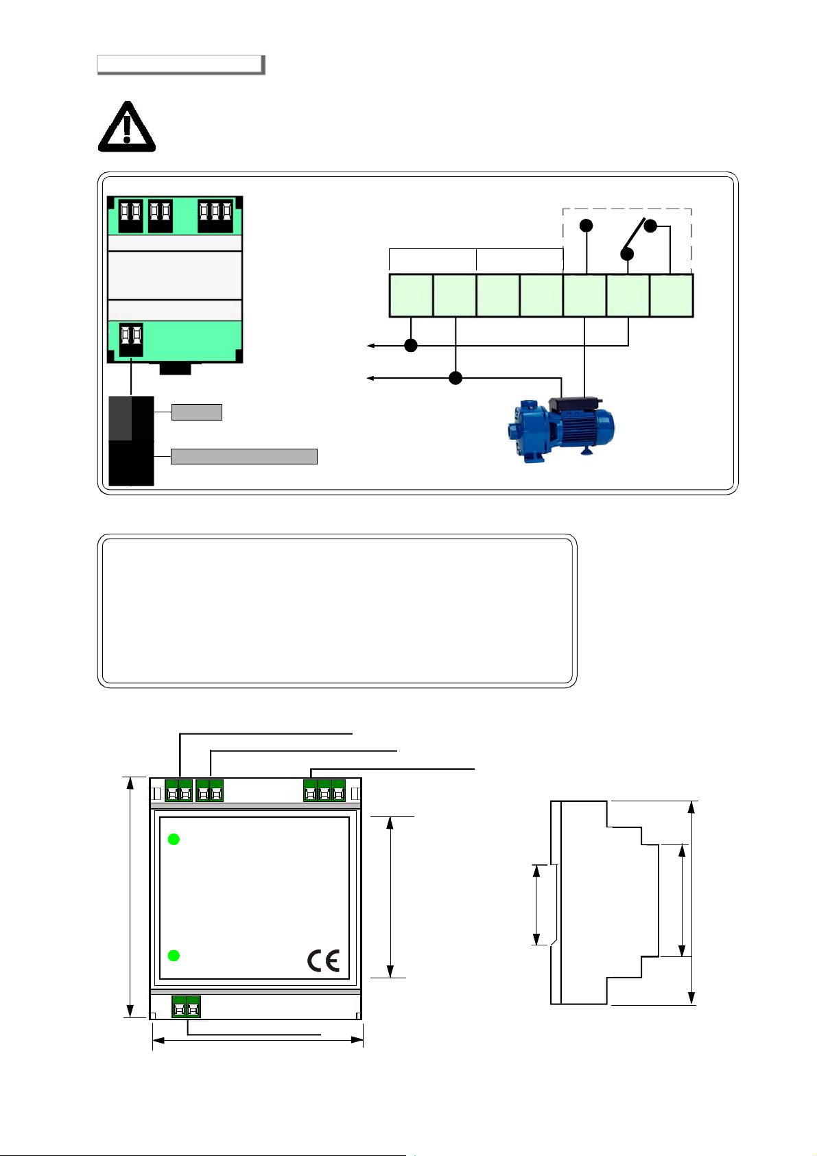
SL200 Sliders 1 "1/4
SL600 Slider 1/8
SL150 Stem in stainless inox
PL150 Prolongs Stem in stainless inox
Antifloodingprobe
Probes Adaptable for Functioning
Power Supply ....................................................................................................... 230/240 VAC ±10%
Power demand ............................................................................................................. 1 W @230 VAC
Insulation ......................................................................................................................... Class II
Power Supply ................................................................................................................ 12 VDC ±10%
Power demand ............................................................................................................... 1 W @24 VDC
Range of contacts ................................................................................................... 10A 250V resistive
Max distance between probe and control unit ................................................................................. 100 m
Section connecting cables probe .................................................................................................. 1 mm
Connection: The cable of connection of the probe must not be installed together with the power
cables.
Operating Temperature ..................................................................................... from -10° C to + 60° C
Min and Max operating Humidity ................................................................................. lower than 95% RH
Body Material probe ........................................................................................... self extinguishing plastic
Degree of protection ...................................................................................................... IP20 in the air
Omega-type size DIN EN 50092 3 modules ................................................................................... 52*90*52
mounting: ........................................................................................................................... electric board
Electromagnetic Compatibility "CE"........................................................According to Reference EN regulations
Technical Specifications
Page 3
Performance
water Probes
reached Position
contacts
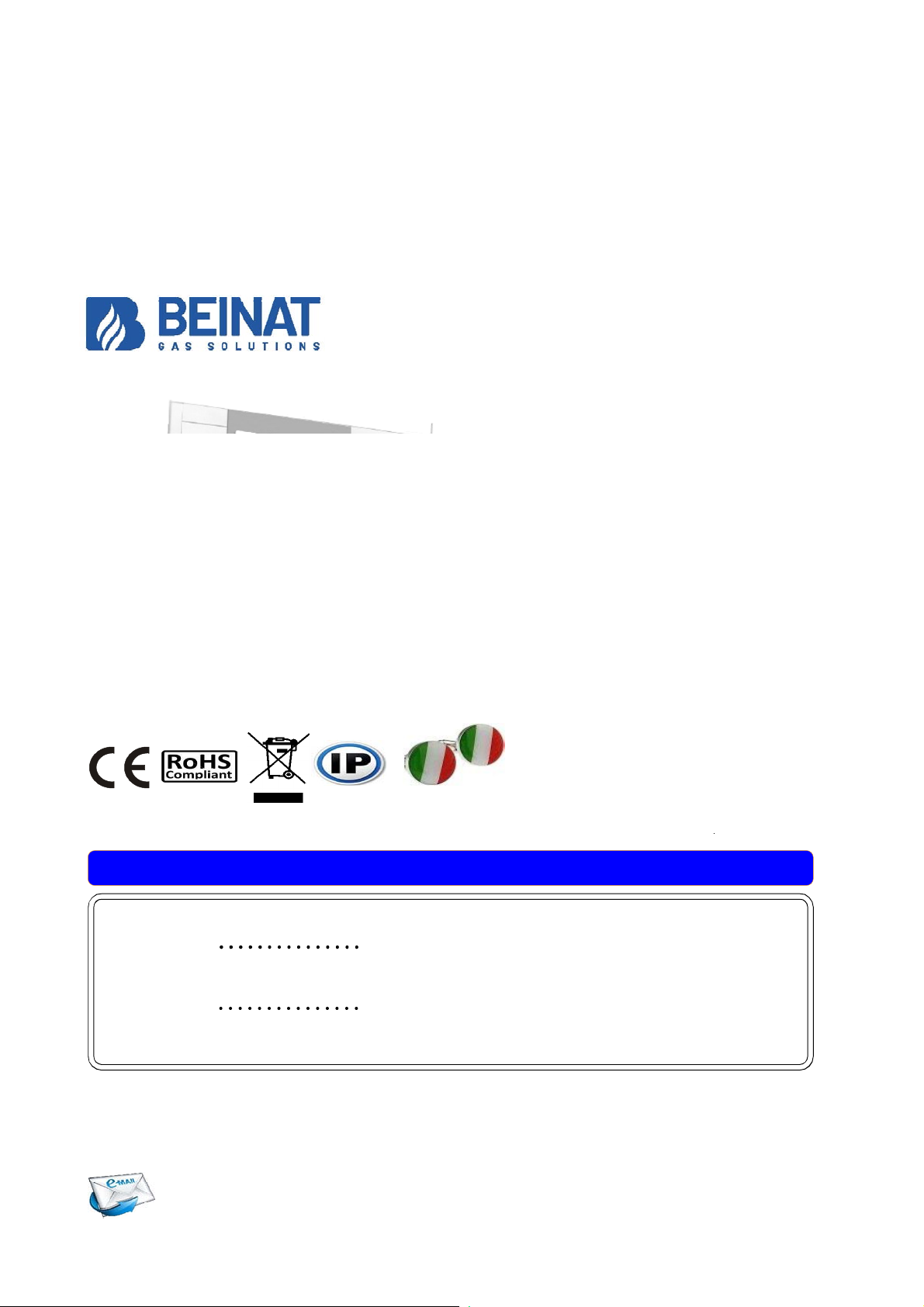
Collegamenti elettrici
ATTENZIONE
Prima di effettuare il collegamento alla rete elettrica assicurarsi che la tensione sia quella richiesta.
Seguire attentamente le istruzioni, e i collegamenti rispettando le Normative vigenti.
Un interruttore automatico o sezionatore (opportunamente identificato come dispositivo di sezionamento
del rilevatore) deve essere incorporato nell'impianto elettrico, adeguatamente posizionato e facilmente
raggiungibile.
ATTENTION !!
The Relay is voltage free
C
NC
NO
1 2 3 4 5 6 7
12/24VAC/VDC
230 VAC
230 VAC
1 2 3 4 5 6 7
1 2
Maximum level probe
Common probe
1 2
Increasing None In connection C and NA
Increasing Common and Minimum In connection C and Na
Decreased Common and Minimum In connection C and NA
Decreased Common In connection C and NC
90 mm
45 mm
37 mm
52 mm
90 mm
44 mm
ILDA100
Connection Probes
Power supply 230 VAC
Connection 12/24 VAC/VDC
Connection pump relay
ON relay
Power
BE-V.1 09 18
Business - info@beinat.com
Help Desk - laboratorio@beinat.com
BEINAT S.r.l.
Via Fatebenefratelli 122/C 10077, S. Maurizio C/se (TO) - ITALY
Tel. 011.921.04.84 - Fax 011.921.14.77
http:// www.beinat.com
IP20 Made in Italy
Lo styling è della b & b design
Stamp and signature of the dealer
Date of purchase:
Serial number:
Beinat S.r.l. following the purpose of improving its products, reserves the right to change the technical, aesthetic and functional characteristics
at any time and without giving any notice.
Switch ILDA100
INSURANCE. This device is insured by the SOCIETÀ REALE MUTUA for the PRODUCT'S GENERAL LIABILITY
up to a maximum of 1,500,000.00 EURO against damages caused by the device in case of failures in functioning.
WARRANTY. The warranty term is 3 years from manufacturing date, in agreement with the following
conditions. The components acknowledged as faulty will be replaced free of charge, excluding the replacement
of plastic or aluminium cases, bags, packing, batteries and technical reports.
The device must arrive free of shipment charges to BEINAT S.r.l.
Defects caused by unauthorized personnel tampering, incorrect installation and negligence resulting from
phenomena outside normal functioning shall be excluded from the warranty.
BEINAT S.r.l. is not liable for possible damage, direct or indirect, to people, animals, or things; from product
faults and from its enforced suspension of use.
DISPOSAL OF OLD ELECTRICAL & ELECTRONIC EQUIPMENT.
This symbol on the product or its packaging to indicates that this product shall not be treated as household waste. Instead, it shall be handed over to
the applicable collection point for the recycling of electrical and electronic equipment, such as for example:
- sales points, in case you buy a new and similar product
- local collection points (waste collection center, local recycling center, etc...).
By ensuring this product is disposed of correctly, you willhelp prevent potential negative consequence for the environment and human health, which could
otherwise be caused by inappropriate waste handing of this product. The recycling of materials will help to conserve natural resources. For more detailed
information about recycling of this product, please contact your local city office, your household waste disposal service or the shop where you purchased
theproduct.
Attention: in some countries of the European Union, the product is not included in the field of application of the National Law that applies the European
Directive 2002/96/EC and therefore these countries have no obligation to carry out a separate collection at the “end of life” of the product.
Table of contents


