1
List of Figures
2
3
5
7
9
10
11
13
15
17
18
19
21
24
25
26
27
28
31
32
33
34
43
46
Standard Cabinet Dimensions
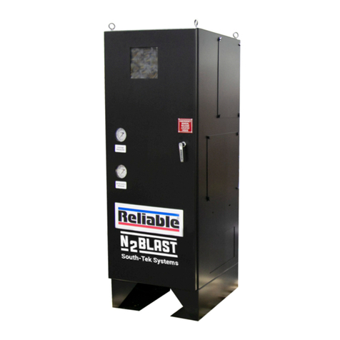
Nitrogen Generator Cabinet Dimensions
Type D Single, Double, Interlock Preaction Components
Type F Double Interlock Preaction Components
DDX-LP Dry System Components
Wet Pilot Line Limitations
Deluge Wet Pilot Line System Components
Deluge Dry Pilot Line System Components
Deluge Electric Release System Components
Single Interlock Preaction Dry Pilot Line System Components
Wet Pilot Line Limitations
Single Interlock Preaction Wet Pilot Line System Components
Type PL Double Interlock Preaciton System Components
Factory Installed Electrical Devics
Potter PFC4410-RC Releasing Control Panel
Pressure & Tamper Switch Wiring
Solenoid and Air Compressor Wiring
Optional CoilKeeper™Wiring
24 VDC Terminal Block (Units with Integral Panel)
Class A Detector Circuit Wiring Example
Class B Detector Circuit Wiring Example
Output Device (Notication) Wiring Example
24VDC Terminal Block (Units without Integral Panel)
Supervisory Air/Nitrogen Pressure Requirements
Figure 1
Figure 2
Figure 3
Figure 4
Figure 5
Figure 6
Figure 7
Figure 8
Figure 9
Figure 10
Figure 11
Figure 12
Figure 13
Figure 14
Figure 15
Figure 16
Figure 17
Figure 18
Figure 19
Figure 20
Figure 21
Figure 22
Figure 23
Figure 24
Description Page
1. Introduction
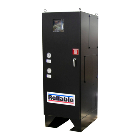
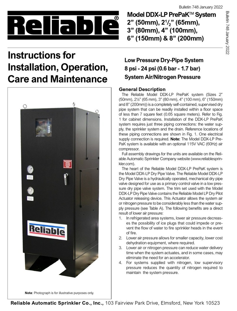
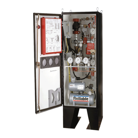
The Reliable Model DDX PrePaK™is a completely self-contained, supervised system that can be readily installed within a floor
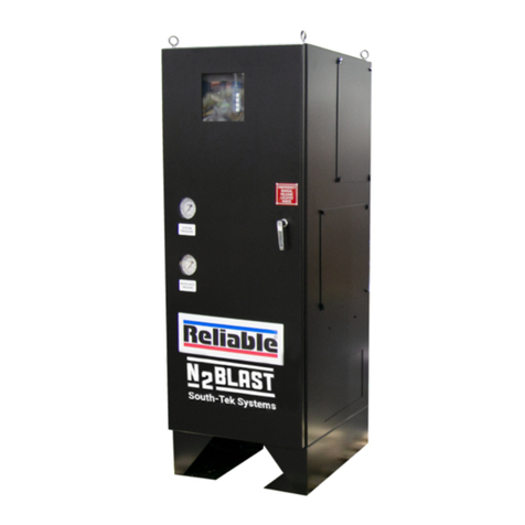
space (not including door swing) of 4.7 ft2(0.43 m2) for 2” through 4” systems, and 6.5 ft2(0.60 m2) for 6” and 8” systems and
those systems incorporating a nitrogen generator.
Installation of the PrePaK™requires three piping connections: the water supply, the sprinkler system, and the drain. Reference
locations of these piping connections, along with general PrePaK™ dimensions are shown on gures 1 and 2 of this document.
Individual power circuits are required for the releasing control panel, air compressor, and nitrogen generator, where so
equipped. Depending on the type of system and requirements of the project, eld wiring of detection devices and noticaiton
devices may be required. When equipped with an integral releasing conrol panel, connection of the panel to the main building
re alarm system may also be required.
2. Scope
This document is intended to provide detailed information on the installation, operation, and maintenance of Reliable Model
DDX PrePaK™cabinet mounted systems. Basic information for the selection and ordering of units is provided on technical
bulletin 760 that is available on the Reliable website (www.reliablesprinkler.com).
This document does not contain information on the design, applicability, or installation of the automatic re detection system
that may be necessary for complete operation of the system. Design and installation of re detection and alarm systems must
be performed by qualied design professionals and approved by all authorities having jurisdiction.
This document is not intended to replace or revise any requirements of the National Fire Protection Association (NFPA), FM
Global, and/or any authorities having jurisdiction (AHJ) that may govern an installation. Design and installation requirements
for re protection systems must be independently evaluated by qualied design professionals and approved by all authorities
having jurisdiction.
3. Product Descriptions & References
Pages 4 through 21 provide descriptions of each available system, additional (related) product references, and diagrams of
major system components. Full assembly drawings are available on the Reliable website (www.reliablesprinkler.com).
ii.
