BEL Melcher X Series User manual
belfuse.com/power-solutions
BCD20021-G Rev AF, 29 November 2021
X Series
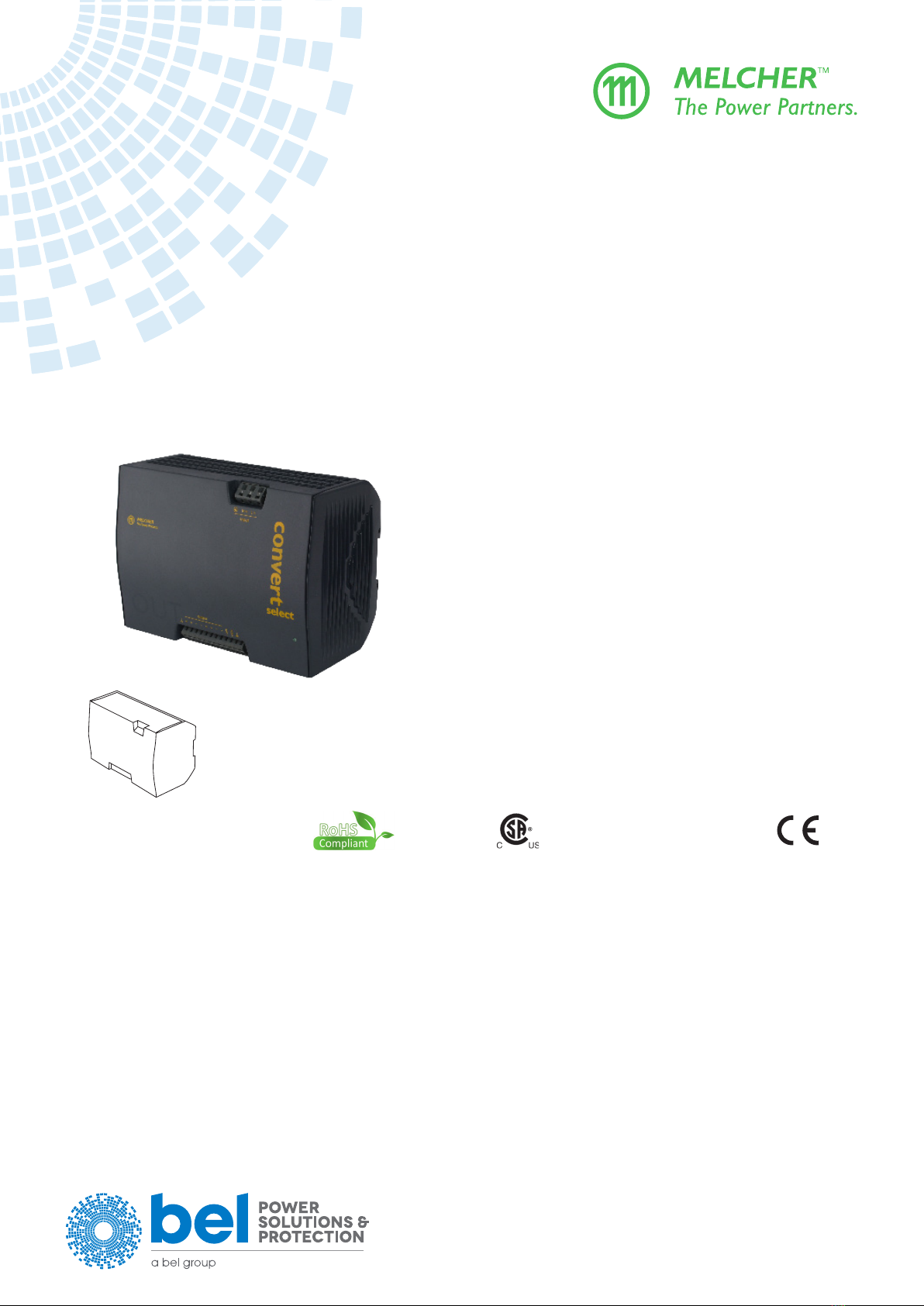
375, 500 Watt AC-DC & DC-DC DIN-Rail Converters
Convert Select
Features
• RoHS lead-free-solder and lead-solder-exempted
products are available
• Rugged35mmDIN-railsnap-tdesign
• Class I equipment
• Universal AC-input with single stage conversion AC-DC
or DC-DC, input 100 –240 VAC or 90– 350 VDC
• Power factor correction, harmonics IEC/EN 61000-3-2
• Virtually no inrush current
• Immunity to IEC/EN 61000-4-2, -3, -4, -5, -6, -8, -11
• Emissions according to EN 55011/55032
• Veryhigheciency;upto89%
• Short-term output peak power capability, rectangular
current limiting characteristic
• Single or two independently regulated outputs with
24, 36, or 48 V
• Outputs no-load, overload, and short-circuit proof
• PCBs protected by lacquer
• Very high reliability
• Safety according to IEC/EN 62368-1, UL/CSA 60950-1
Table of Contents
Description............................................................................2
Model Selection....................................................................2
Functional Description..........................................................4
Electrical Input Data .............................................................6
Electrical Output Data...........................................................9
Electromagnetic Compatibility (EMC).................................14
Immunity to Environmental Conditions...............................17
Mechanical Data.................................................................19
Safety and Installation Instructions.....................................20
Description of Options ........................................................23
Accessories ........................................................................28
Battery Charging /Temperature Sensor..............................29
114
4.49"
194
7.64"
138
5.43"

belfuse.com/power-solutions
BCD20021-G Rev AF, 29 November 2021
Page 2 of 26
X Series
375, 500 Watt AC-DC and DC-DC DIN-Rail Converters
© 2021 Bel Power Solutions & Protection
Description
The Convert Select front end series represents a family of DIN-rail mountable DC-DC and AC-DC converters with power factor
correction. The converters have been designed according to the latest industry requirements and standards. They are ideal
for use in outdoor and other demanding applications to power building control systems, factory automation, industrial controls,
instrumentation, electromagnetic drives, fans, and other DC loads. Dierent models are available with a single output or two
independently regulated, electrically isolated outputs with 24, 36, or 48 V. Special models for battery charging are available.
Key features of the Convert Select line include power factor correction with low harmonic distortion, negligibly low inrush current,
high immunity to transients and surges, and low electromagnetic emissions. Internal protection circuits such as input over- and
undervoltage lockout, thermal protection, as well as output overvoltage protection by a second control loop ensure safe operation
ofthenalsystem.
The outputs deliver an electrically-isolated Electrical energy source class 1 (ES1), (except models LXR/LXN1740) and low output
noise. They are no-load, overload, and short-circuit proof. The electronically controlled short-term peak power capability of up to
150%oftheratedoutputpowerenablesthefrontendconverterstodeliveradditionalpowertostart-upmotorsortosafelyoperate
subsequent circuit breakers. Built-in large sized output capacitors absorb possible reverse energy, which may be caused by quick
deceleration of electromagnetic drives connected directly to the output. A green LED at the front cover displays the status of the
output(s).
The Convert Select Series was designed according to all relevant international safety standards. Adequate clearances and
creepage distances allow operation in pollution degree 2 environment. All board assemblies are coated with a protective lacquer.
The thermal concept allows operation at full load up to an ambient temperature of 60 °C in free air without forced cooling. A rugged
DINsnap-tdeviceallowseasyandreliablexingontothevarious35mmDIN-railmodels.Theconvertersarettedwithcage
clamp terminals easily accessible from the front. System connectors with screw terminals for use with pre-assembled harnesses,
external adjustment of the output voltage, as well as various auxiliary functions are available as options.
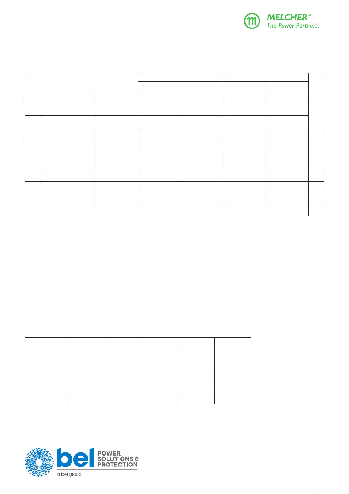
Model Selection
Table 1: Standard models
Output 1 Output 2 Output
Power
Operating Input
Voltage
Type
Designation Eciency Options3, 5
Vo1 nom
[VDC]
Io1 nom
[A]
Vo2 nom
1
[VDC]
Io2 nom
[A]
Po nom
[W] Vi min – Vi max
ηmin
7
[%]
24.7 15 - - 371
8 5 2– 264 VAC,
47 – 63 Hz 4,
90 2– 350 VDC6
LXR1601-6G 87
R
D1, D2, D5
M1, M2
F, K2
non-G
24.7 20 - - 494 LXN1601-6G 87
37.05 10 - - 371 LXR1701-6G 388
37.05 13.4 - - 497 LXN1701-6G 3 88
49.4 7.5 - - 371 LXR1801-6G 88
49.4 10 - - 494 LXN1801-6G 88
24.7 10 24.7 10 494 LXN2660-6G 87
37.05 6.7 37.05 6.7 497 LXN2770-6G 388
49.4 5 49.4 5 494 LXN2880-6G 88
1 R-input not connected.
2For derating at low input voltage see section Output Power Derating.
3For minimum quantity and lead times contact Bel Power Solutions.
4 Theconvertershavebeentestedupto440Hz;foroperatingfrequencies<47Hzor>63HzcontactBelPowerSolutions.
5On double-output models the options R, M2, D1, D2, D5 are related to the 2nd output only.
6Vi≤250 VDC for models with option F
7 Min.eciencyatVi nom, Io nom, and TA=25°C.Typicalvaluesareapprox.2%better.
Not for new designs (NFND) or End of Life (EOL).
Table 2: Battery charger models (M1 included)

belfuse.com/power-solutions
BCD20021-G Rev AF, 29 November 2021
Page 3 of 26
X Series
375, 500 Watt AC-DC and DC-DC DIN-Rail Converters
© 2021 Bel Power Solutions & Protection
Output Voltage Nominal Output Values Operating Input
Voltage
Type
Designation Eciency Options 3, 5
VBat
[VDC]
Vo safe
1
[VDC]
Vo max
[VDC]
Vo nom
5
[VDC]
Io nom
5
[A]
Po nom
5
[W] Vi min – Vi max
ηmin
7
[%]
24 25.68 1 29.3 27.3 12.6 344
8 5 2– 264 VAC,
47 – 63 Hz 4,
90 2– 350 VDC6
LXR1240-6M1G 87
F, K2
non-G
16.8 458 LXN1240-6M1G 87
36 38.52 1 43.95 40.88 8.4 343 LXR1840-6M1G
387
11.2 458 LXN1840-6M1G
3 87
48 51.36 1 58.6 54.5 6.3 343 LXR1740-6M1G 87
8.4 458 LXN1740-6M1G 87
1Setting voltage (typ.) with open R-input
2For derating at low input voltage see section Output Power Derating.
3For minimum quantity and lead times consult the factory.
4 Theconvertershavebeentestedupto440Hz;foroperatingfrequency<47Hzor>63Hzcontactthefactory
5 Nominaloutputgures,calculatedwithacellvoltageof2.27Vat20°C.
6Vi≤250 VDC for models with option F.
7 Min.eciencyatVi nom, Vo nom,Io nom, and TA=25°C.Typicalvaluesareapprox.2%better.
Not for new designs (NFND) or End of Life (EOL).
Part Number Description
L X N 2 6 60 -6 D2 F K2 G
Input voltage range............................................................... L
Series ....................................................................................X
Nominal output power
325 W............................................................... R
500 W............................................................... N
Number of outputs............................................................. 1, 2
Typespecication ....................................................000 – 999
Operational ambient temperature range TA
–40 to 60 °C .....................................................-6
EWorcustomer-specic .............................-0, -5
Options Output voltage control input
1........................... R
Save data signal 1............................. D1, D2, D5
Multiple functions via
D-SUB
connector
1. M1, M2
Built-in second fuse, input diode .......................F
System connector ...........................................K2
RoHS compliant for all six substances 2 .......... G
1Only one of these options is possible.
2 ModelswithoutthesuxG(non-Goption)donotuselead-freesolder.
Note: The sequence of options must follow the order above.
Not for new designs (NFND) or End of Life (EOL).
Example: LXN2660-6D2FK2G: Power factor corrected AC-DC converter, operating input voltage range 85 – 264 VAC, 2 electrically isolated
and individually regulated outputs, each providing 24.7 V, 10 A, options D2, F, K2, and RoHS-compatible for all 6 substances.
Product Marking
Basic type designation, applicable safety approval and recognition marks, CE mark, warnings, pin designation, Company logo.
Specictypedesignation,inputvoltagerange,nominaloutputvoltagesandcurrents,degreeofprotection,batchandserial
number, data code including production site, version, date of production.
belfuse.com/power-solutions
BCD20021-G Rev AF, 29 November 2021
Page 4 of 26
X Series
375, 500 Watt AC-DC and DC-DC DIN-Rail Converters
© 2021 Bel Power Solutions & Protection
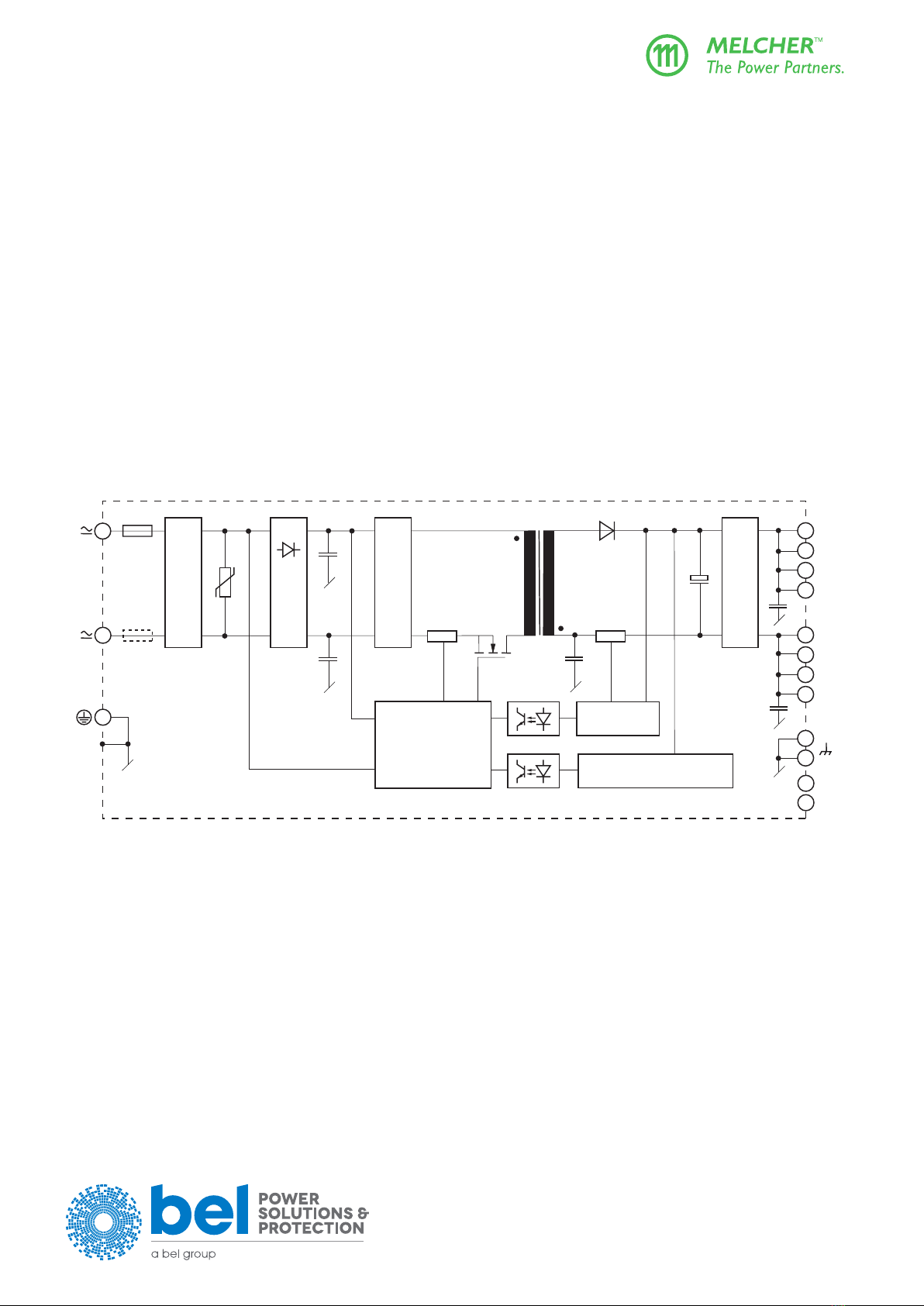
Functional Description
TheXSeriesconvertersareprimarycontrolledAC-DCorDC-DCybackconverterswithaconstantswitchingfrequencyof130kHz.
Thepower-factor-correctedsingle-stepconversionoftheinputvoltagetoalowoutputvoltageresultsinextremelyhigheciency.
Dependingontheoutputpower,theconvertersarettedwiththree(375W)orfour(500W)powertrains.Modelswithfourpowertrains
have one or two outputs. Double-output models exhibit individual control of each output.
Theinputvoltageisfedviafuse,lter,andrectiertothepowertrainswithmaintransformersdesignedinplanartechnique.Theinput
lterwithverysmallinputcapacitancegeneratesvirtuallynoinrushcurrent.Aninputtransientsuppressorprotectstheconverter
against high voltage peaks and surges. Input over- and undervoltage lockout as well as input current limitation protect the converter
fromoperationoutsideofitsspecication.Theinputvoltagewaveformissensedbytheprimarycontrollogictoallowactivepower
factor correction, forcing the input current to follow the input voltage waveform.
Thesecondarysideofeachmaintransformersuppliesviatherectierdiodealargeelectrolyticoutputstoragecapacitorprovidingfor
the hold-up time. Double-output models exhibit an individual control logic for each output. The output voltage and the output current
are measured and fed back to the primary control logic via an optocoupler. A second control loop monitors the output voltage. It
disables the output in the case of a failure in the control logic and limits the output voltage.
Built-in temperature sensors monitor the internal temperature of each powertrain. If the temperature exceeds the limit, the converter
reducestheoutputpowercontinuouslytokeepthetemperaturebelowitslimit.AgreenLEDonthefrontcoverconrmsthepresence
of the output voltage(s).
The R input (option R, M1, or M2) allows for external adjustment of the output voltage by means of a resistor or an external voltage
source.AnexternalsensorcanbeconnectedtotheRinputandallowsfortemperature-controlledbatterycharging;seeAccessories.
Input lter
Input lter
Vo/Iocontrol
Output lter
2
nd
control loop (ES1)
Control circuit
including
PFC and
input OVP/UVP
L
N
Vo+
Vo–
Cy
CyCy
CY
CY
Aux1
Fuse
2
1
03105
Shunt Shunt
3
4
5
8
9
2
3
6
7
1
12
10
Aux2
11
2
nd
fuse
(option F)
Rectier
Fig. 1
LXR 375 W single-output converter.

belfuse.com/power-solutions
BCD20021-G Rev AF, 29 November 2021
Page 5 of 26
X Series
375, 500 Watt AC-DC and DC-DC DIN-Rail Converters
© 2021 Bel Power Solutions & Protection
Input lter
Cy
Cy
Fuse
2
1
03106
3
Input lter
Vo/Iocontrol
Output lter
2nd control loop (ES1)
Control circuit
including
PFC and
input OVP/UVP
Vo+
Vo–
Cy
Cy
Cy
Shunt Shunt
4
5
2
3
Input lter
Vo/Iocontrol
Output lter
2nd control loop (ES1)
Control circuit
including
PFC and
input OVP/UVP
Vo+
Vo–
Cy
Cy
Cy
Aux1
Shunt Shunt
8
9
6
7
12
10
Aux2
11
1
L
N
2nd fuse
(option F)
Rectier
+
+
Fig. 2
LXN 500 W double-output converter
For the pinout of 500 W single-output models see g. 1.
belfuse.com/power-solutions
BCD20021-G Rev AF, 29 November 2021
Page 6 of 26
X Series
375, 500 Watt AC-DC and DC-DC DIN-Rail Converters
© 2021 Bel Power Solutions & Protection
Electrical Input Data
General conditions:
TA= 25 °C, unless TCisspecied.
Table 3: Input data LW models
Input LXR LXN Unit
AC Input DC Input AC Input DC Input
Characteristics Conditions min typ max min typ max min typ max min typ max
Vi
Operating input voltage
range
Io= 0 – Io nom
Tc – Tc max
85 2264 902350385 2264 9023503
V
Vi nom
Rated input voltage
range 100 (230) 240 220 100 (230) 240 220
fiRated input frequency150 – 60 - 50 – 60 - Hz
IiInput current Io nom, Vi = Vi nom 1.9 1.95 2.6 2.6 A
Io nom, Vi = Vi min 5.2 5.0 7.0 6.6
Pi0 No-load input power Vi min – Vi max 3 3 3 3 W
Iinrush Inrush current Vi max , t >0.1ms 5 5 5 5 A
CiInput capacitance 5 5 6 6 µF
PF Power factor Vi nom = 230 V, Io nom 0.90 - 0.9 -
Vi RFI
Conducted input RFI EN 55011/55032
Vi nom, Io nom
A A A A
Radiated input RFI
fswitch Switching frequency 130 130 130 130 kHz
1 Foroperatingfrequencies<47Hzand>63Hzcontactthefactory.Theconvertershavebeentestedupto440Hz.
2Output power derating at low input voltage and/or high case temperature TC;seeOutput Power Derating.
3Vi≤250 VDC for models with option F.
Output Power Derating
The output power of LX models must be decreased at low input voltage and/or powertrain temperature above 125 °C.
The powertrain temperature depends on the output power, the input voltage, and the cooling method. At low input voltage the
lossesincrease.AtthemaximumspeciedenvironmenttemperatureTAfreeairconvectioncoolingmightbeinsucient.Asa
result, the output power has to be reduced according to the tables 4 and 5.
Note: ThemeasurementshavebeenmadeattheapprovaltestswithfreeairconvectioncoolingaccordingtoUL60950-1,speciedambient
temperature TA,andwiththeconverterbuiltinacardboardboxaccordingtoUL508andaspeciedtemperatureoutsidetheboxTout. The
tables give a correlation between TAor Tout and the case temperature TC(measuring point TCsee Mechanical Data).Formodelsnotspecied,
contact the factory.
Table 4: Poderating according to UL 60950-1 at TA= 60 °C, or according to UL 508 at Tout = 50 °C
Model Po nom
[W]
TC max
[°C]
Derate below Derate by
Vi [VAC] Vi [VDC] [W/V]
LXR1601-6 371 84 125 115 - 1.8
LXR1701-6 371 84 125 115 - 1.8
LXR1801-6 371 84 125 115 - 1.8
LXN1601/2660-6 494 84 125 115 - 1.8
LXN1701-6 497 84 125 115 - 2.5
LXN1801/2880-6 494 84 125 115 - 2.5

belfuse.com/power-solutions
BCD20021-G Rev AF, 29 November 2021
Page 7 of 26
X Series
375, 500 Watt AC-DC and DC-DC DIN-Rail Converters
© 2021 Bel Power Solutions & Protection
Table 5: Poderating according to UL 60950-1 at TA= 50 °C, or according to UL 508 at Tout = 40 °C
Model Po nom
[W]
TC max
[°C]
Derate below Derate by
Vi [VAC] Vi [VDC] [W/V]
LXR1601-6 371 78 100 no derating - 1.5
LXR1701-6 371 78 100 no derating - 1.5
LXR1801-6 371 78 100 no derating - 1.5
LXN1601/2660-6 494 78 100 no derating - 2
LXN1701-6 497 78 100 no derating - 2
LXN1801/2880-6 494 78 100 no derating - 2
Input Fuse and Protection
A slow blow fuse ( Schurter T10A, 5 ×20 mm), protected by a sleeve, is connected in the line input. For DC input voltages above
250VanexternalDCfuseoracircuitbreakermustbeinstalled;observetheInstallation Instructions.
Converters with option F have 2 fuses, one in each input line. The D C input voltage for all converters with option F is limited to 250 V.
AVDRandasymmetricalinputlterformaneectiveprotectionagainstinputtransients.
An under- and overvoltage lockout protects the converter by disabling it below Vimin and above Vi max.
Thebuilt-inbridgerectierprovidesreversepolarityprotectionattheinputifoperatedfromDC.
Eciency
0 0.2 0.4 0.6 0.8 1
50
70
60
80
90
η[%]
Io
Io nom
Vi= 125 V rms Vi= 230 V rms
04068a
Fig. 3
Eciency versus load

belfuse.com/power-solutions
BCD20021-G Rev AF, 29 November 2021
Page 8 of 26
X Series
375, 500 Watt AC-DC and DC-DC DIN-Rail Converters
© 2021 Bel Power Solutions & Protection
Power Factor, Harmonics
All converters feature active power factor correction.
0
1
2
3
4
3579 11 13
mA/W
04067a
Limit class D according
to IEC/EN 61000-3-2
Harm.
LXN1601-6
0 0.2 0.4 0.6 0.8 1
0
0.1
0.2
0.3
0.4
0.5
0.6
0.7
0.8
0.9
1.0
PF
04066a
I
o
I
o nom
V
i
= 125 VAC
V
i
= 230 VAC
Fig. 4
Harmonic currents at input current, measured at
Vi= 230 VAC, Io= Io nom (LXN1601-6)
Fig. 5
Power factor versus load
Electrical Output Data
Table 6a: Output data of 375 Watt standard models. General conditions: TA= 25 °C, unless TA is specied; R input open-circuit
Model LXR1601 LXR1701 LXR1801 Unit
Characteristics Conditions min typ max min typ max min typ max
Vo nom Output voltage nominal 1Vi nom, Io nom 24.25 24.7 25.2 36.37 37.05 37.8 48.5 49.4 50.4 V
*24.55 24.7 24.85 36.82 37.05 37.28 49.1 49.4 49.7
Vo worst Output voltage range of
tolerance
Vi min – Vi max,
Io= (0.1 – 1) Io nom
24.0 25.8 36.0 38.7 48.0 51.6
Vo L Overvoltage protection 28.5 30 42.75 45 57 60
Po nom Nominal output power Vi = 100 V – Vi max 371 371 371 W
Io nom Output current nominal Vi = 100 V – Vi max 15 10 7.5 A
Io L Output current limit 3Vi = 100 V – Vi max 15.1 17.2 10.1 11.4 7.57 8.7
Iop Output current boost
4 typ. 1 s 22.5 15 11.3
Ripple and noise
Vi = 230 VAC,
fi
= 50 Hz, Io nom
100 100 100
mVpp
110021200212002
∆Vo u Static line regulation 100 VAC –Vi max, Io nom ±0.1 ±0.15 ±0.15 V
∆Vo I Static load regulation
(droop)
Vi nom
Io= (0.1 – 1) Io nom
–0.4 –0.6 –0.8
vod Dynamic load regulation
Voltage deviation
Recovery time
Vi nom ,
Io
= (0.5 ↔1) Io nom
±1.2 ±1.5 ±1.8
40 80 80 ms
αvo Temperaturecoecient TC min – TC max ±0.02 ±0.02 ±0.02 %/K
tor Start-up time Vi= 0 →Vi nom,Io nom 700 700 700 ms
toh min Hold-up time Io nom,
Vo nom →0.8 Vo nom
15 20 25
* Converters with version V105 or higher
1 Setting voltage with open R-input
2Superimposed low frequency ripple at 2 • fi
3Rectangular current limit characteristic (continuous operation)
4 Short-termpeakpowercapability150%ofPo nom for approx. 1 s

belfuse.com/power-solutions
BCD20021-G Rev AF, 29 November 2021
Page 9 of 26
X Series
375, 500 Watt AC-DC and DC-DC DIN-Rail Converters
© 2021 Bel Power Solutions & Protection
Table 6b: Output data of 500 Watt single-output standard models. General conditions as per table 6a.
Model LXN1601 LXN1701 LXN1801 Unit
Characteristics Conditions min typ max min typ max min typ max
Vo nom Output voltage nominal 1Vi nom, Io nom 24.25 24.7 25.2 36.37 37.05 37.8 48.5 49.4 50.4 V
*24.55 24.7 24.85 36.82 37.05 37.28 49.1 49.4 49.7
Vo worst Output voltage range of
tolerance
Vi min – Vi max,
Io= (0.1 – 1) Io nom
24.0 25.8 36.0 38.7 48.0 51.6
Vo L Overvoltage protection 28.5 30 42.75 45 57 60
Po nom Nominal output power Vi = 100 V – Vi max 494 497 494 W
Io nom Output current nominal Vi = 100 V – Vi max 20 13.4 10 A
Io L Output current limit 3Vi = 100 V – Vi max 20.1 22.8 13.5 15.2 10.1 11.4
Iop Output current boost
4 typ. 1 s 30 20 15
Ripple and noise
Vi = 230 VAC,
fi
= 50 Hz, Io nom
100 100 100 mVpp
2110021200212002
∆Vo u Static line regulation 100 VAC –Vi max, Io nom ±0.1 ±0.15 ±0.15 V
∆Vo I Static load regulation
(droop)
Vi nom,Io= (0.1 – 1) Io nom –0.4 –0.6 –0.8
vod Dynamic load regulation
Voltage deviation
Recovery time
Vi nom,
Io
= (0.5 ↔1) Io nom
±1.2 ±1.5 ±1.8
40 80 80 ms
αvo Temperaturecoecient TC min – TC max ±0.02 ±0.02 ±0.02 %/K
tor Start-up time Vi= 0 →Vi nom,Io nom 700 700 700 ms
toh min Hold-up time Io nom,Vo nom →0.8 Vo nom 15 20 25
Table 6c: Output data of 500 Watt double-output models. General conditions as per table 6a.
Model LXN2660 LXN2770 LXN2880 Unit
Characteristics Conditions min typ max min typ max min typ max
Vo nom Output voltage nominal 1Vi nom, Io nom 24.25 24.7 25.2 36.37 37.05 37.8 48.5 49.4 50.4 V
*24.55 24.7 24.85 36.82 37.05 37.28 49.1 49.4 49.7
Vo worst Output voltage range of
tolerance
Vi min – Vi max,
Io= (0.1 – 1) Io nom
24.0 25.8 36.0 38.7 48.0 51.6
Vo L Overvoltage protection 28.5 30 42.75 45 57 60
Po nom Nominal output power Vi = 100 V – Vi max 494 497 494 W
Io nom Output current nominal Vi = 100 V – Vi max 2 x 10 2 x 6.7 2 x 5 A
Io L Output current limit 3Vi = 100 V – Vi max 10.1 11.4 6.8 7.7 5.1 5.7
Iop Output current boost
4 typ. 1 s 2 x 15 2 x 10 2 x 7.5
Ripple and noise
Vi = 230 VAC,
fi
= 50 Hz, Io nom
100 100 100 mVpp
2110021200212002
∆Vo u Static line regulation 100 VAC –Vi max, Io nom ±0.1 ±0.15 ±0.15 V
∆Vo I Static load regulation
(droop)
Vi nom,Io= (0.1 – 1) Io nom –0.4 –0.6 –0.8
vod Dynamic load regulation
Voltage deviation
Recovery time
Vi nom,
Io
= (0.5 ↔1) Io nom
±1.2 ±1.5 ±1.8
40 80 80 ms
αvo Temperaturecoecient TC min – TC max ±0.02 ±0.02 ±0.02 %/K
tor Start-up time Vi= 0 →Vi nom,Io nom 700 700 700 ms
toh min Hold-up time Io nom,Vo nom →0.8 Vo nom 15 20 25
* Converters with version V105 or higher
1 Setting voltage with open R-input
2Superimposed low frequency ripple at 2 • fi
3Rectangular current limit characteristic (continuous operation)
4 Short-termpeakpowercapability150%ofPo nom for approx. 1 s
belfuse.com/power-solutions
BCD20021-G Rev AF, 29 November 2021
Page 10 of 26
X Series
375, 500 Watt AC-DC and DC-DC DIN-Rail Converters
© 2021 Bel Power Solutions & Protection
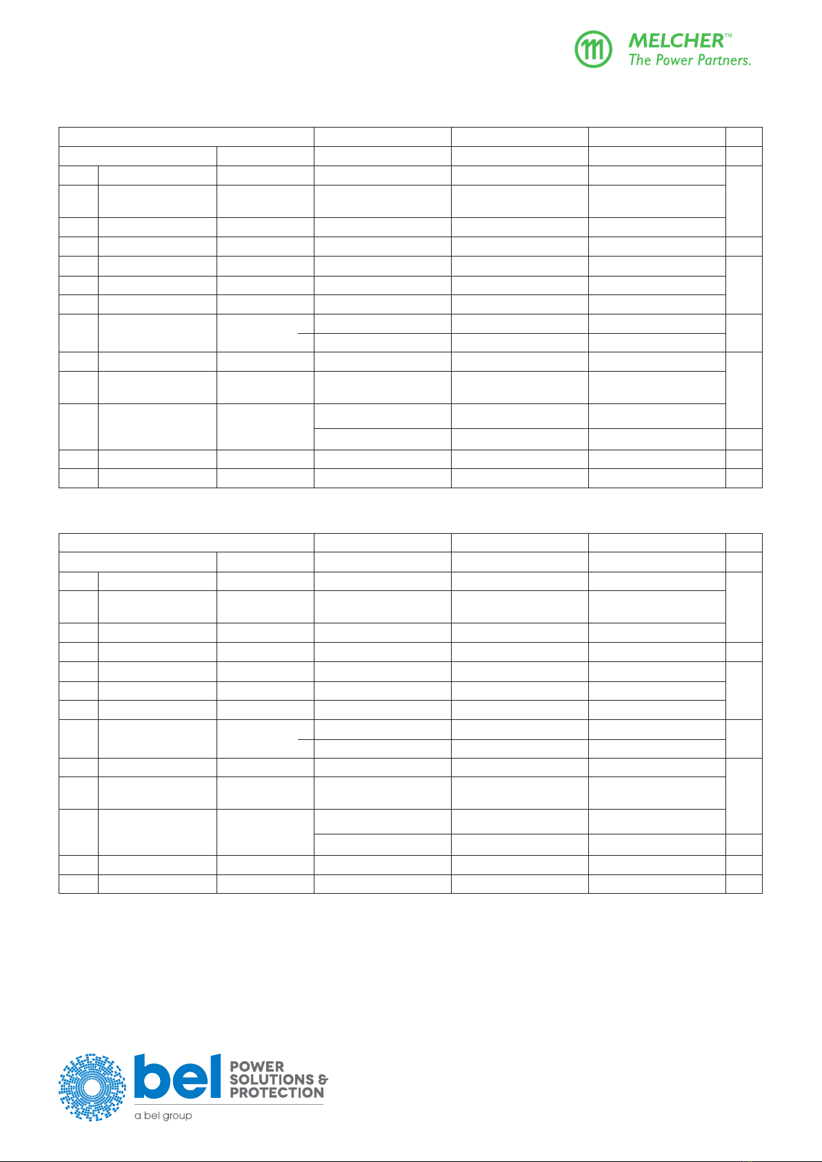
Table 7a: Output data of 350 Watt battery charger models.
General conditions: TA= 25 °C, unless TAis specied; R input left open-circuit, unless otherwise specied
Model LXR1240-6M1 LXR1840-6M1 LXR1740-6M1 Unit
Characteristics Conditions min typ max min typ max min typ max
Vo safe Output setting voltage 1Vi nom, Io nom 24.5 25.68 26.3 36.75 38.52 39.45 49 51.36 52.6 V
VBat Output voltage (max)
controlled by R input
Vi min – Vi max,
Io= (0.1 – 1) Io nom
29.3 43.95 58.6
Vo L Overvoltage protection 30.9 32.5 46.35 48.75 61.8 65
Po nom Output power nominal Vi = 100 V – Vi max 344 343 343 W
Io nom Output current nominal Vi = 100 V – Vi max 12.6 8.4 6.3 A
Io L Output current limit Vi = 100 V – Vi max 12.7 15 8.5 10 6.36 7.5
Iop Output current boost 3typ. 1 s 18.9 12.6 9.5
voRipple & noise Vi = 230 VAC,
fi
= 50 Hz, Io nom
100 100 100 mVpp
2110021200212002
∆Vo u Static line regulation 100 V –Vi max, Io nom ±0.1 ±0.15 ±0.15 V
∆Vo I Static load regulation
(droop)
Vi nom,
Io
= (0.1 –1) Io nom
–0.4 –0.6 –0.8
vod Dynamic load regulation
Voltage deviation
Recovery time
Vi nom ,
Io
= (0.5 ↔1) Io nom
±1.2 ±1.6 ±1.9
40 80 80 ms
αvo Temperaturecoecient TC min – TC max ±0.02 ±0.02 ±0.02 %/K
tor Start-up time Vi= 0 →Vi nom,Io nom 700 700 700 ms
Table 7b: Output data of 500 Watt battery charger models. General conditions as per table 7a
Model LXN1240-6M1 LXN1840-6M1 LXN1740-6M1 Unit
Characteristics Conditions min typ max min typ max min typ max
Vo safe Output setting voltage 1Vi nom, Io nom 24.5 25.68 26.3 36.75 38.52 39.45 49 51.36 52.6 V
VBat Output voltage (max)
controlled by R input
Vi min – Vi max,
Io= (0.1 – 1) Io nom
29.3 43.95 58.6
Vo L Overvoltage protection 30.9 32.5 46.35 48.75 61.8 65
Po nom Output power nominal Vi = 100 V – Vi max 458 458 458 W
Io nom Output current nominal Vi = 100 V – Vi max 16.8 11.2 8.4 A
Io L Output current limit Vi = 100 V – Vi max 16.9 20 11.3 13.3 8.5 10
Iop Output current boost 3typ. 1 s 25.2 16.8 12.6
voRipple & noise Vi = 230 VAC,
fi
= 50 Hz, Io nom
100 100 100 mVpp
2110021200212002
∆Vo u Static line regulation 100 V –Vi max, Io nom ±0.1 ±0.15 ±0.15 V
∆Vo I Static load regulation
(droop)
Vi nom,
Io
= (0.1 –1) Io nom
–0.4 –0.6 –0.8
vod Dynamic load regulation
Voltage deviation
Recovery time
Vi nom ,
Io
= (0.5 ↔1) Io nom
±1.2 ±1.6 ±1.9
40 80 80 ms
αvo Temperaturecoecient TC min – TC max ±0.02 ±0.02 ±0.02 %/K
tor Start-up time Vi= 0 →Vi nom,Io nom 700 700 700 ms
1 Setting voltage with open R-input = Vo safe
2 Superimposed low frequency ripple at 2 • fi
3Rectangular current limit characteristic (continuous operation)
4 Short-termpeakpowercapability150%ofPo nom for approx. 1 s

belfuse.com/power-solutions
BCD20021-G Rev AF, 29 November 2021
Page 11 of 26
X Series
375, 500 Watt AC-DC and DC-DC DIN-Rail Converters
© 2021 Bel Power Solutions & Protection
Parallel Operation
Double-output models exhibit an independent control logic each. Both outputs can be connected in parallel, provided that the
optionsS(includedinM1)andRarenotused,sincetheyinuenceonlythe2nd output. The two pairs of powertrains share the
current due to their output voltage droop characteristic.
Up to 3 converters with the same output voltage may be operated in parallel. It is possible to parallel W Series with X Series
converters.
Reasonable current sharing is achieved by the droop characteristic. Correct mode of operation is highly dependent upon the wiring
of the converters and the impedance of these wires. Use wires with equal length and equal cross sections of min. 1.5 mm 2. The
bestresultsforparalleloperationcanbeachievedwiththewiringshowning.6.
Paralleloperationofsingle-outputmodelsusingoptionR(outputvoltageadjust)ispossible,butnotrecommended.Refertog.
6;theconnectionsbetweenthepins8and9(bothVo–)shouldbeasshortaspossible.
Note: Parallel operation is not possible, if a temperature sensor is connected, as the sensor eliminates the output voltage droop.
Vo+ 2
Vo+ 3
Vo- 4
Vo- 5
Vo- 8
Vo- 9
Vo+ 6
Vo+ 7
AUX1 10
Vo+ 2
Vo+ 3
Vo- 4
Vo- 5
Vo- 8
Vo- 9
Vo+ 6
Vo+ 7
AUX1 10
Vo+ 2
Vo+ 3
Vo- 4
Vo- 5
Vo- 8
Vo- 9
Vo+ 6
Vo+ 7
AUX1 10
V
i
V
i
V
i
Load
11053a
Additional wiring for output currents I
o
≥ 10 A
Additional wiring, if using the R-input
V
R
+
_
Fig. 6
Wiring for single-output converters connected in parallel. Additional wiring for higher output currents and with the use of option R is shown.
Series Connection
Series connection of several outputs up to 150 V is possible. The output is not ES1, when the max. output voltage exceeds 60 V.
belfuse.com/power-solutions
BCD20021-G Rev AF, 29 November 2021
Page 12 of 26
X Series
375, 500 Watt AC-DC and DC-DC DIN-Rail Converters
© 2021 Bel Power Solutions & Protection
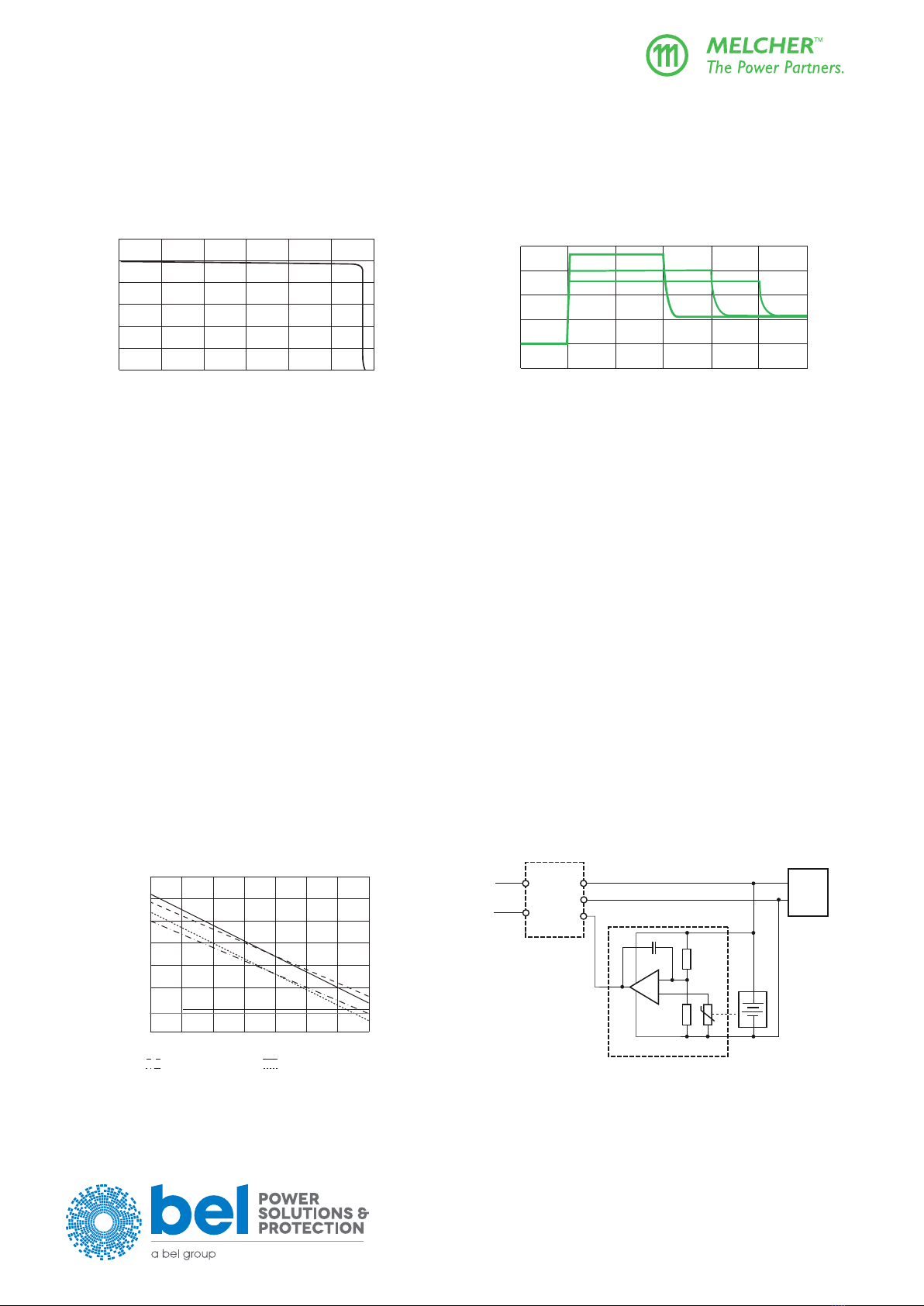
Output Characteristic and Protection
Theoutputcharacteristic,individualforeachgroupofpowertrains,isrectangularwithadrooptoeaseparalleloperation;seeg.7.
However,a50%higheroutputcurrentispossibleforashorttime,suchallowingstart-upofloadsorchargingofcapacitors;seeg.8.
Each output is independently protected against internal overvoltage by means of a second control loop. When the output voltage
exceeds Vo L, the respective output is disabled.
0.8
1.0
0.6
0.4
0.2
000.20.40.60.81.01.2
I
o
/I
o nom
V
o
/V
o nom
05181a
1.4
1.6
1.2
1.0
0.8
0.6
-- 0.5 0.5 1.5 2.5 s
I
o
/ I
o nom
05194b
012
Fig. 7
Voversus Io(single-output model, typical values).
Fig. 8
Short term peak power characteristic: overcurrent versus
time (typical values).
Overtemperature Protection
Each powertrain is independently protected against overtemperature by a built-in temperature sensor. When a certain temperature
is reached, the concerned powertrain reduces its output power continuously.
Thermal Considerations
Thethermalconditionsareinuencedbyinputvoltage,outputcurrent,airow,andtemperatureofsurroundingcomponents.TAmax
is therefore, contrary to TC max, an indicative value only.
Caution: The installer must ensure that under all operating conditions TCremains within the limits stated in the table Temperature specications.
Note: SucientforcedcoolingallowsTAto be higher than TA max provided that TC max is not exceeded. It is recommended that continuous
operation under worst case conditions of the following 3 parameters be avoided: Minimum input voltage, maximum output power, and
maximum temperature.
Battery Charging and Temperature Sensor
The battery charger models exhibit the option M1 and have been designed to charge lead-acid batteries. The R-input allows for
connectingabattery-specictemperaturesensor,whichprovidestemperature-controlledadjustofthetricklechargevoltage.This
optimizeschargingaswellasbatterylifetime.Dependinguponthecellvoltageandthetemperaturecoecientofthebattery,
dierentsensortypesareavailable;see Accessories.
Note: Parallel operation is not possible, if the temperature sensor is connected to the paralleled outputs Vo+, as the sensor eliminates the
output voltage droop.
However, it is possible to insert bleeding resistors in the Vo+ output lines of each converter in order to create a droop of approx. 0.6 V @ Io nom
for 24 V outputs (1.2 V @ Io nom for 48 V outputs), but this creates considerable power losses.
2.10
2.15
2.20
2.25
2.30
2.35
2.40
2.45
Cell voltage [V]
–20 –10 0 10 20 30 40 50 °C
06139b
VC= 2.27 V, –3 mV/K VC= 2.27 V, –3.5 mV/K
V
C
= 2.23 V, –3 mV/K V
C
= 2.23 V, –3.5 mV/K
Vo safe
Power
supply
Load
–
+
Input Vo–
R
Temperature sensor
03099d
Battery
Vo+
+
Fig. 9
Trickle charge voltage versus temperature for dierent tem-
perature coecients (Vo safe with disconnected sensor)
Fig. 10
Schematic circuit diagram of a system with battery backup
and temperature-controlled charging.

belfuse.com/power-solutions
BCD20021-G Rev AF, 29 November 2021
Page 13 of 26
X Series
375, 500 Watt AC-DC and DC-DC DIN-Rail Converters
© 2021 Bel Power Solutions & Protection
Electromagnetic Compatibility (EMC)
Electromagnetic Immunity
TheXSerieshasbeensuccessfullytestedtothefollowingspecications:
Table 8: Electromagnetic immunity (type tests)
Phenomenon Standard Level Coupling mode 1Value
applied
Waveform Source
imped.
Test procedure In
oper.
Perf.
crit. 2
Electrostatic
discharge
(to case)
IEC/EN
61000-4-2
4 3contact discharge 8000 Vp1/50 ns 330Ω
150 pF
10 positive and
10 negative
discharges
yes A
air discharge 15000 Vp
Electromagnetic
eldRF
IEC/EN
61000-4-3
x 4antenna 20 V/m AM80%/1kHz N/A 80 – 800 MHz yes A
5 antenna 20 V/m AM80%/1kHz N/A 80 – 1000 MHz yes A
10 V/m 1400 – 2000 MHz
5 V/m 2100 – 2700 MHz
3 V/m 5100 – 6000 MHz
Electrical fast
transients/burst
IEC/EN
61000-4-4
3 6capacitive, o/c ±2000 Vpbursts of 5/50 ns
2.5/5kHzover15ms;
burst period: 300 ms
50Ω 60 s positive
60 s negative
transients per
coupling mode
yes A
4 ±i/c, +i/–i
direct
±4000 Vp
Surges IEC/EN
61000-4-5
3 7+i/c, – i/c ±2000 Vp1.2 / 50 µs 12Ω 5 pos. & 5 neg.
surges per
coupling mode
yes B
2 7+i/– i ±1000 Vp1.2 / 50 µs 2Ω
Conducted
disturbances
IEC/EN
61000-4-6
3 8i, o, signal wires 10 VAC AM80%/1kHz
(140dBμV)
150Ω 0.15 – 80 MHz yes A
Power frequency
magneticeld
IEC/EN
61000-4-8
9–100 A/m 50 and 60 Hz – x, y, and z axis yes A
1 i = input, o = output, c = case.
2 A=Normaloperation,nodeviationfromspecs;B=Normaloperation,temporarylossoffunctionordeviationfromspecs.possible
3 Exceeds EN 50121-3-2:2016 table 5.3 and EN 50121-4:2016 table 2.4.
4 Corresponds to EN 50121-3-2:2016 table 5.1 and EN 50121-4:2016 table 2.1.
5 Complies with EN 50121-3-2:2016 table 5.2 and EN 50121-4:2016 table 2.2.
6 Complies with EN 50121-3-2:2016 table 3.2 and EN 50121-4:2016 table 3.2.
7 Complies with EN 50121-3-2:2016 table 3.3 and EN 50121-4:2016 table 3.3.
8 Corresponds to EN 50121-3-2:2016 table 3.1 and EN 50121-4:2016 table 3.1 (radio frequency common mode).
9 ComplieswithEN50121-4:2016table2.3(Powerfrequencymagneticeld,ACinput).
Emissions
Limit: 61204bqp Detector: Peak, conducted Vi+, TÜV-Divina, 2011-04-21
LXN1601-6, Ui=230 VAC, Uo=24 V, Io= 20 A
dBµV
0.2 0.5 1 2 5 10 20 MHz
JM235
20
40
60
80
EN 55011 A qp
EN 55011 A av
30 50 100 200 500 1000 MHz
dBµV/m
10
20
30
40
0
60
VLXN1601-6, Ui=230 VAC, Uo=24 V, Io= 20 A
Testdistance 10 m, EN 55011+A1:2010, Group 1, Class A, 2011-04-19
JM236
50
Fig. 11
Conducted emissions for LXN1601-6:
Typical disturbances, peak and quasi-peak at input L as per
EN 55011, measured at Vi= 230 VAC and Io nom.
Fig. 12
Radiated emissions for LXN1601-6:
Typical electromagnetic eld strength (quasi-peak) in 10 m
distance as per EN 55011, Vi nom and Io nom.
Ferrite KEKitagawa TRCN-28-16-20 with 2 turns on input cable.

belfuse.com/power-solutions
BCD20021-G Rev AF, 29 November 2021
Page 14 of 26
X Series
375, 500 Watt AC-DC and DC-DC DIN-Rail Converters
© 2021 Bel Power Solutions & Protection
Table 9: Harmonics and icker
Phenomenon Standards Conditions Results
Harmonics EN 61000-3-2:2006 Vi= 230 V, Vo nom, Io nom Class A, D
Voltageuctuationandicker EN 61000-3-3 + A2:2005 Vi= 230 V, Vo nom, Io nom Complied
Immunity to Environmental Conditions
Table 10: Mechanical stress and climatic
Test method Standard Test Conditions Status
Cab Damp heat steady
state
IEC/EN 60068-2-78
MIL-STD-810D section 507.2
Temperature: 40 ±2 °C Converter
not operating
Relative humidity: 93 +2/-3 %
Duration: 56 days
Kb Salt mist, cyclic
(sodium chloride
NaCl solution)
IEC/EN 60068-2-52 Concentration: 5%(30°C) Converter
not operating
Duration: 2 h per cycle
Conditions: 40°C,93%rel.humidity
Storage Duration: 3 cycles of 22 h
Eb Bump
(half-sinusoidal)
IEC/EN 60068-2-29
MIL-STD-810D sect. 516.3
Acceleration amplitude: 25 gn= 245 m/s2Converter
not operating,
wall mounted 1
Bump duration: 11 ms
6000 bumps: 1000 in each direction
Acceleration amplitude: 10 gn= 98.1 m/s2Converter
not operating,
on DIN-rail 2
Bump duration: 11 ms
6000 bumps: 1000 in each direction
Fc Vibration
(sinusoidal)
IEC/EN 60068-2-6
MIL-STD-810D sect. 514.3
Acceleration amplitude: 0.35 mm (10 – 60 Hz) Converter
operating,
wall mounted 1
Frequency (1 Oct/min): 5 gn= 49 m/s2(60 – 2000 Hz)
Test duration: 7.5 h (2.5 h each axis)
Acceleration amplitude: 0.25 mm (10 – 60 Hz) Converter
operating,
on DIN-rail 2
Frequency (1 Oct/min): 2 gn= 19 m/s2(60 – 2000 Hz)
Test duration: 7.5 h (2.5 h each axis)
Ea Shock
(half-sinusoidal)
IEC/EN 60068-2-27
MIL-STD-810D sect. 516.3
Acceleration amplitude: 50 gn= 490 m/s2Converter
not operating,
wall mounted 1
Bump duration: 11 ms
Number of bumps: 18 (3 in each direction)
Fh Random vibration
broad band, digital
control & guidance
IEC/EN 60068-2-64 Acceleration spectral density: 0.05 gn
2 / Hz Converter
operating,
wall mounted 1
Frequency band: 20 – 500 Hz
Acceleration magnitude: 4.9 gn rms
Test duration: 3 h (1 h each axis)
Fda Random vibration
wide band, high
reproducibility
IEC/EN 60068-2-35 Acceleration spectral density: 0.01 gn
2 / Hz Converter
operating,
mounted on
DIN-rail 2
Frequency band: 20 – 500 Hz
Acceleration magnitude: 2.2 gn rms
Test duration: 1.5 h (0.5 h each axis)
1 Wall-mountedwithbracketsUMB-W[HZZ00618];see Accessories
2 FastenedonaDIN-railwith2additionalDIN-railxingbracketsDMB-EWG;see Accessories. This also covers wall-mounting with brackets,
because wall mounting performs better in vibration test.
belfuse.com/power-solutions
BCD20021-G Rev AF, 29 November 2021
Page 15 of 26
X Series
375, 500 Watt AC-DC and DC-DC DIN-Rail Converters
© 2021 Bel Power Solutions & Protection
Temperatures
Table 11: Temperature specications, valid for an air pressure of 800 - 1200 hPa (800 - 1200 mbar)
Model Standard models -6 Unit
Characteristics Conditions min max
TAAmbient temperature Converter operating1–40 60 °C
TCCase temperature 2–40 90 2
TSStorage temperature Non operational –40 85
1See Thermal Considerations
2See table 5 Poderating
Failure Rates
Table 12: MTBF
Values at specied
case temperature
Module types Ground benign
40 °C
Ground xed Ground mobile
50 °C
Unit
40 °C 70 °C
MTBF 1 LXN1801-6 400 000 110 000 50 000 40 000 h
1Calculated in accordance with MIL-HDBK-217E, notice 2.

belfuse.com/power-solutions
BCD20021-G Rev AF, 29 November 2021
Page 16 of 26
X Series
375, 500 Watt AC-DC and DC-DC DIN-Rail Converters
© 2021 Bel Power Solutions & Protection
Mechanical Data
138 (5.43")
106.6 (4.2")
113.6 (4.47")
15 (0.59")
213.8 (8.42")
194 (7.64")
33 (1.3")
49 (1.93")
S09127d
199 (7.83")
Wall mounting
brackets
(accessories)
Measuring point for
case temperature TC
TATA
TC
~ 40 (1.6")
13 (0.51")
29.4 (1.16")
43 (1.69")
31 (1.22")LED
x axis
z axis
(vertical)
European
Projection
Option M
Option M
(female
connector)
D-SUB
(male con-
nector)
Option M
(female connector)
Fig. 13
Case X01
LXR: weight approx. 2600 g
LXN: weight approx. 2800 g
Case designed by ATP, Munich.
belfuse.com/power-solutions
BCD20021-G Rev AF, 29 November 2021
Page 17 of 26
X Series
375, 500 Watt AC-DC and DC-DC DIN-Rail Converters
© 2021 Bel Power Solutions & Protection
Safety and Installation Instructions
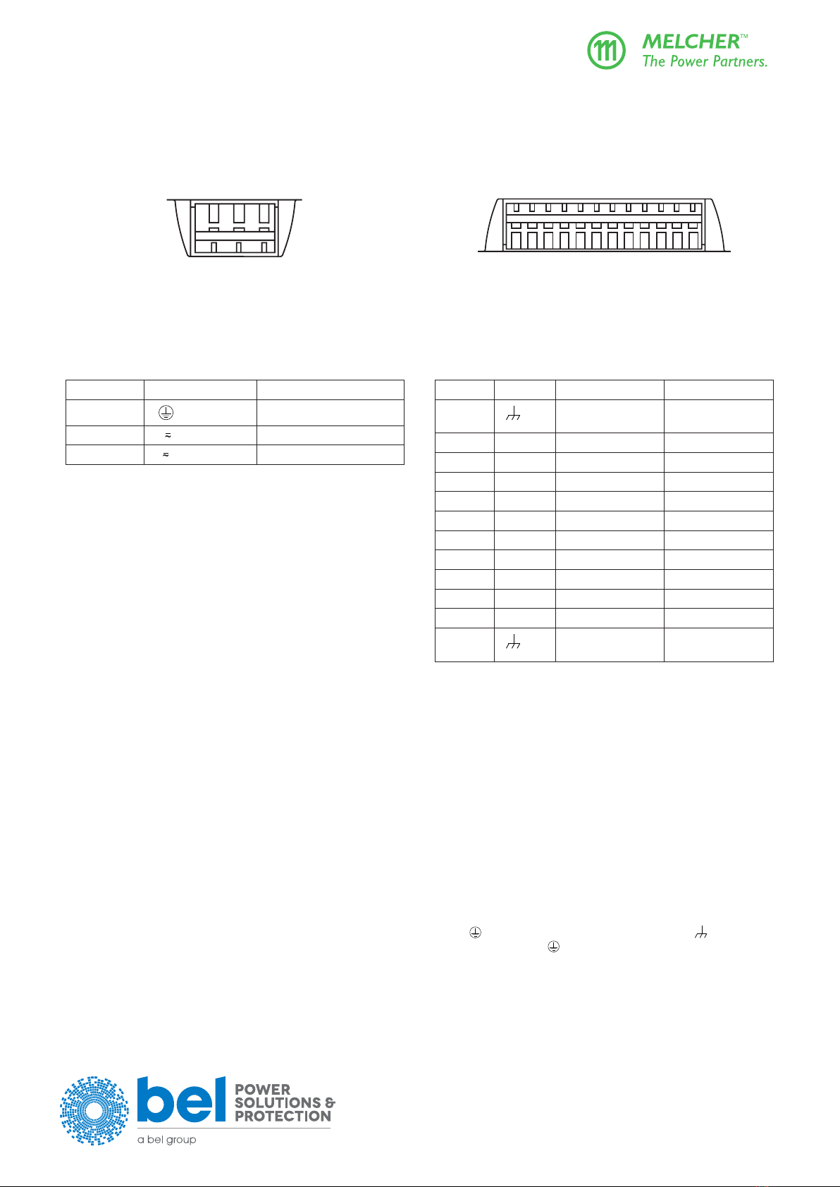
Terminal Allocation
Theterminalallocationtablesdenetheelectricalpotentialoftheconverters.
13
2
10066
13 5 79
10086
24 6 810 12
11
Fig. 14a
View of the input terminals (cage clamp style)
Fig. 14b
View of the output terminals (cage clamp style)
Table 13a: Input terminals of LX models Table 13b: Terminal allocation output side
Pin no. Pin designation Electrical determination
1Protective earth PE
2 N
~
Input neutral, DC negative
3 L
~
Input phase, DC positive
Pin no. Pin des. Single output Double output
1 Functional earth
to load
Functional earth
to load
2 + Output positive Output 1 positive
3 + Output positive Output 1 positive
4 – Output negative Output 1 negative
5 – Output negative Output 1 negative
6 + Output positive Output 2 positive
7 + Output positive Output 2 positive
8 – Output negative Output 2 negative
9 – Output negative Output 2 negative
10 AUX1 Option 1 Option 1
11 AUX2 Option 2 Option 2
12 Functional earth
to load
Functional earth
to load
Installation Instructions
The X Series converters are components, intended exclusively for inclusion within other equipment by professional installers. The
installation must strictly follow the national safety regulations in compliance with the enclosure, mounting, creepage, clearance,
casualty, markings and segregation requirements of the end-use application.
DIN-rail mountingispossiblewiththebuilt-insnap-tdeviceonaDIN-rail.Thisfulllsthemechanicaltransportrequirementsas
per ETSI 300019-1-2, class 2 (vertical).
TofullltherequirementsofIEC721-3-2,class2.1(vertical),2additionalxingbracketsHZZ00624-G(see Accessories) must be
ttedonthebottomsideoftheDIN-rail.Forheavydutyapplications,werecommendinstallingall4xingbracketsHZZ00624-G.
Chassis or wall mounting is possible with the wall-mounting brackets HZZ00618 (see Accessories). This complies with IEC 721-
3-2, class 2.2 (vertical and horizontal).
Caution:Installtheconvertersvertically,andmakesurethatthereissucientairowavailableforconvectioncooling.Theminimumspace
to the next device should be: top/bottom: 30 mm, left/right: 20 mm.
The converters of the X Series are class I equipment: Input terminal 1 ( ) and the output terminals 1 and 12 ( ) are reliably
connected to the case. For safety reasons it is essential to connect the input terminal 1 ( ) with protective earth. Output terminals
1 and 12 can be used to connect the output voltage(s) or the load to functional earth.
Thephaseinput(L)isinternallyfused;seeInput Fuse and Protection. This fuse is designed to break an overcurrent in case of a
malfunction of the converter and is not customer-accessible.

belfuse.com/power-solutions
BCD20021-G Rev AF, 29 November 2021
Page 18 of 26
X Series
375, 500 Watt AC-DC and DC-DC DIN-Rail Converters
© 2021 Bel Power Solutions & Protection
10073
10072
Fig. 15a
Snap-t mounting to DIN-Rail.
Fig. 15b
Dismounting from DIN-rail. Use proper tool
(min. 3 mm screwdriver) and adequate force.
1
2
3
1007
4
Fig. 16
Cage clamp terminals. Use 0.5 to 2.5 mm2 (AWG 20 to 12) solid or stranded wires depending on local requirements.
External fuses in the wiring to one or both input line (L
~
and/or N
~
) may be necessary to ensure compliance with local requirements.
A built-in second fuse in the neutral path is available as option F.
A second fuse in the wiring to the neutral terminal N or option F is needed if:
• Local requirements demand an individual fuse in each source line
• Neutralandearthimpedanceishighorundened
• Phaseandneutralofthemainsarenotdenedorcannotbeassignedtothecorrespondingterminals(L
~
to phase and N
~
to
neutral).
Models with option F: Caution! Double-pole/neutral fusing.
If the converter operates at source voltages above 250 VDC, an external DC fuse or a circuit breaker at system level should be
installed in the phase input line L
~
.
Caution:
• Installation must strictly follow the national safety regulations.
• Do not open this apparatus!
Protection Degree and Cleaning Agents
TheprotectiondegreeoftheconvertersisIP20.Protectivecoversoverinputandoutputterminalsareavailableonrequest;see
Accessories.
Any penetration of liquid or foreign solid objects has to be prevented, since the converters are not hermetically sealed.
belfuse.com/power-solutions
BCD20021-G Rev AF, 29 November 2021
Page 19 of 26
X Series
375, 500 Watt AC-DC and DC-DC DIN-Rail Converters
© 2021 Bel Power Solutions & Protection
Standards and Approvals
The X Series converters were approved according to UL/CSA 60950-1 and CE declaration according IEC/EN 62368-1.
The converters have been designed in accordance with said standards for:
• Class I equipment
• Power-supply for building-in, vertical mounting on 35 mm DIN-rail or on a wall
• Overvoltage category II (III for 110 VAC supply)
• Basic insulation between input and case, based on 250 VAC
• Double or reinforced insulation between input and output, based on 250 VAC and 350 VDC
• Functional insulation between outputs and case
• Functional insulation between outputs
• Pollution degree 2 environment
The converters are subject to manufacturing surveillance in accordance with the ISO 9001:2015.
See also the Declaration of Conformity (last page).
Railway Applications
The X Series converters have been designed by observing the railway standards EN 50155 and EN 50121. All boards are coated
with a protective lacquer.
Isolation
The electric strength test is performed in the factory as routine test in accordance with EN 62911 and IEC/EN 62368-1 and should
notberepeatedintheeld.TheCompanywillnothonorwarrantyclaimsresultingfromincorrectlyexecutedelectricstrengtheld
tests.
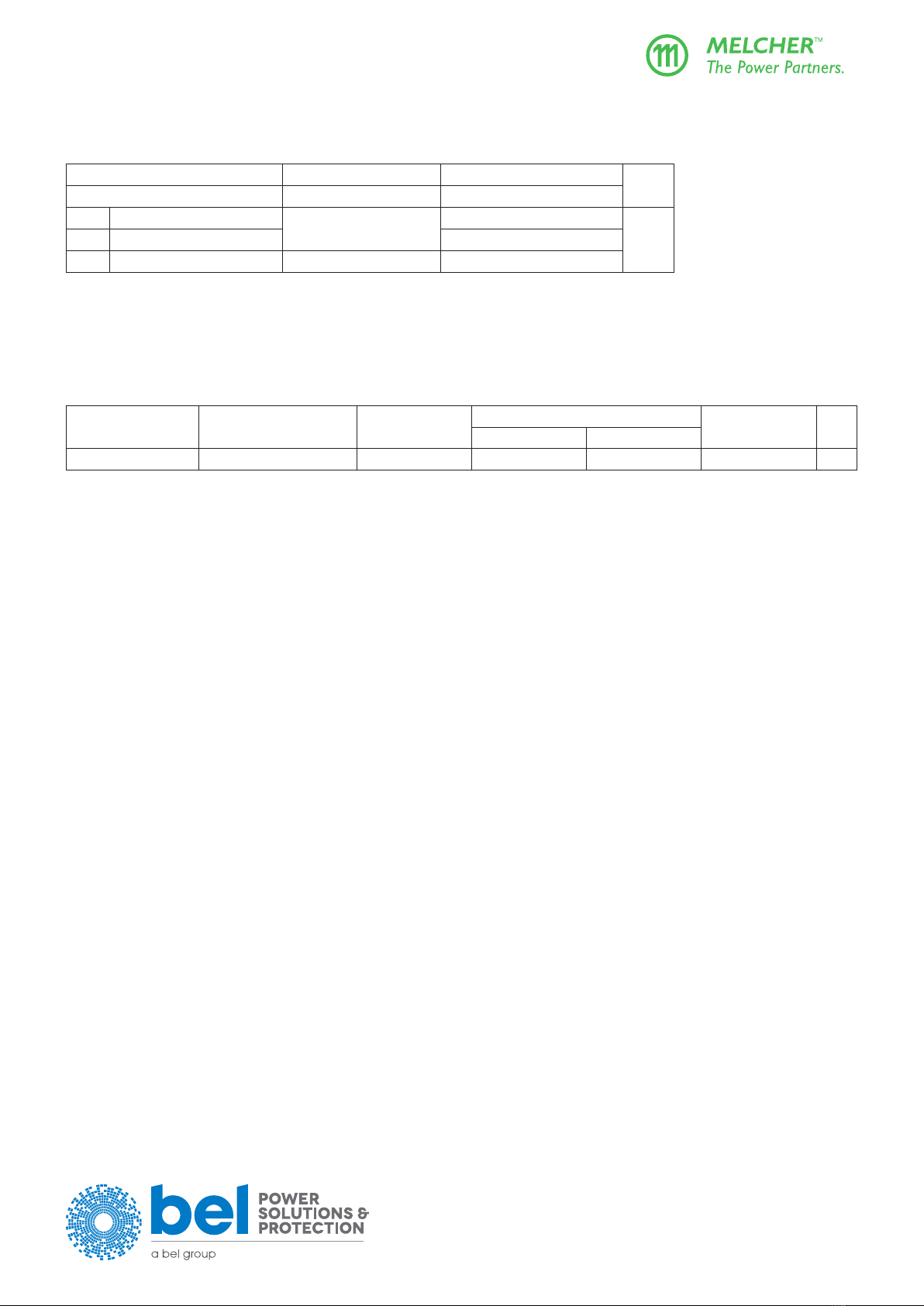
Table 14: Isolation
Characteristics Input to Case
and Output(s)
Output(s) to Case Output 1 to Output 2
and AUX
Unit
Electric strength test Factorytest≥1s 2.8 1 1.4 0.5 kVDC
AC test voltage equivalent
to factory test
2.0 1.0 0.35 kVAC
Insulation resistance >300 2 >300 2 >100 MΩ
1Subassemblies are pretested with 4.2 kVDC.
2Tested at 500 VDC.
Leakage Currents
Leakagecurrentsowduetointernalleakagecapacitance(mainlytheY-capacitors).Thecurrentvaluesareproportionaltothe
voltage Vi and the frequency fiofthesupply(mains).Theleakagecurrentsarespeciedatmaximumoperatinginputvoltage,
provided that phase, neutral, and protective earth are correctly connected as required for class I equipment.
Caution: Leakage current may exceed 5 mA, if fi>63Hz.
Safety of Operator-Accessible Output Circuits
If the output circuit of a converter is operator-accessible, it shall be a ES1 circuit according to the safety standards IEC/EN 62368-1
3rd edition.
The converters have ES1 output circuits up to an output voltage of 57.5 V. However, if the isolated outputs are connected to
anothervoltagesourceorconnectedinserieswithatotalof>57.5V,theoutputsarehazardous.
LED Indicator
A green LED is activated, when the output voltage Vois within the normal operating tolerance band.
Note: This LED is also activated, when the converter is not powered by the input, but a loaded battery is connected to the output.

belfuse.com/power-solutions
BCD20021-G Rev AF, 29 November 2021
Page 20 of 26
X Series
375, 500 Watt AC-DC and DC-DC DIN-Rail Converters
© 2021 Bel Power Solutions & Protection
Description of Options
Single options D1, D2, D5, R are available on the AUX1 terminal (10), referenced to Vo– or Vo2–.
Option M1 and M2 designate a combination of several options accessible via a D-SUB connector or in some cases on the AUX1
and AUX2 terminals. Option M1 includes the function SD.
Note: In double-output models, the options D1, D5, R, and SD concern only output 2 connected to terminals 6, 7, 8, and 9.
Single Options Using the AUX1 Pin
Theconnectionisshowninthegurebelow.ForthedescriptionrefertoAdjustment of Voor Vo2 (next section).
AUX1
1
11
10
9
8
7
6
5
4
3
2
Adjustment with V
ext
AUX1
1
11
10
9
8
7
6
5
4
3
2
Adjustment with R
ext
Vo2+
or Vo+
Vo2–
or Vo–
R
ext1
R
ext2
V
ext
+
Vo2–
or Vo–
1212
06160a
AUX2AUX2
Fig. 17
Connection of adjust resistors or an external voltage source to adjust the output voltage Voor Vo2 (option M1 or M2 not tted)
Multiple Options M1 or M2
The option board is suitable for applications, where several options are needed. Option M1 is standard for battery charger models,
option M2 is suitable for applications without battery or for simple applications with battery.
In general, the multiple options M1 or M2 are connected to an additional D-SUB connector. Some signals (but not option R) can
also be connected to AUX1 and AUX2, if the D-SUB connector is not suitable to the customer.
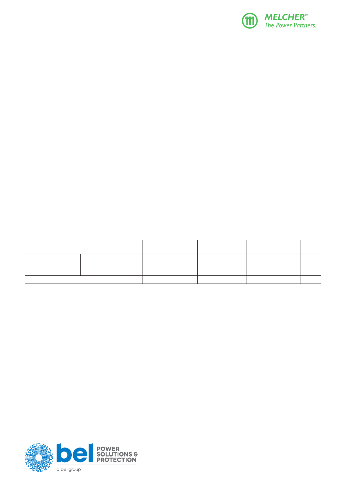
Table 15: Pin allocation of the 9 pin D-SUB connector
Pin Designation Description
1 GND1 1 System ground / common signal return
2 R R input 3
3 VCC 2 Positive supply voltage (≈ output 2)
4 D1 Output voltage monitor Vo low D1
3
5 D5 Output 2 voltage monitor Vo low D5
3
6 SD Shutdown3
7 D-adj Adjustment of threshold values of D1 or D5
8 D2 Input voltage monitor Vi low
9 Sys-OK System okay (all outputs are okay)
1Do not connect GND1 (pin 1) with the neg. output (–)
2Do not connect VCC (pin 3) with the positive output (+)
3 In double-output models, R, D1, D5, SD concern output 2 only.
This manual suits for next models
14
Table of contents
Other BEL Media Converter manuals


Popular Media Converter manuals by other brands


TV One
TV One 1T-DV1394-A70 instruction manual

HIK VISION
HIK VISION DS-6001DI Series Technical manual

Wyrestorm
Wyrestorm CON-H2-SCL quick start guide

Baumer Hübner
Baumer Hübner HOGS 100 S Mounting and operating instructions

Black Box
Black Box CL090A-F manual

TV One
TV One CORIOmaster2 MK2 quick start guide


