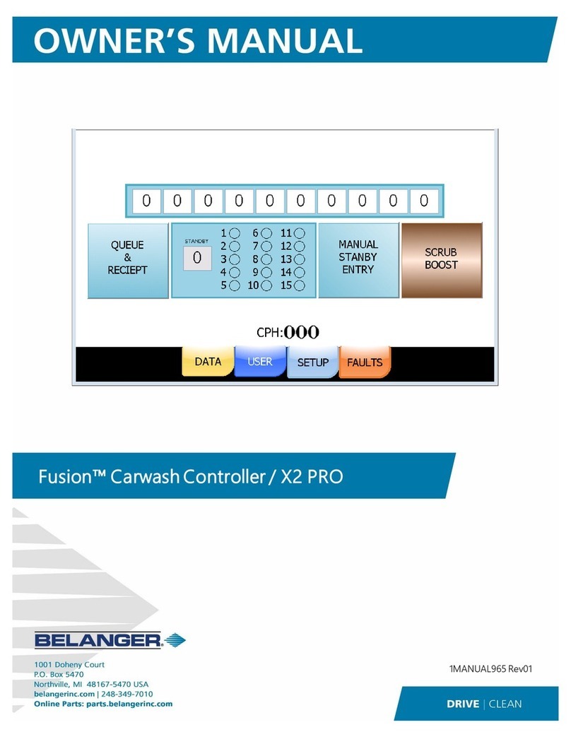
Belanger CUBE User manual


Belanger® Equipment Owner’s Manual
Cube® Controller Programming & Operation
Copyright 2021
Belanger, Inc®
This manual and the accompanying equipment are protected by United States trademark, copyright, and patent laws. You may
make one copy of this manual. Do not make additional copies of this manual or electronically transmit it in any form whatsoever,
in whole or in part, without the prior written permission of Belanger, Inc.®
The registered trademarks used in this document are the property of their respective owners. The use of such trademarks is for
reference purposes only and does not imply sponsorship or approval of Belanger, Inc.®by these companies or any companies
affiliated with their respective owners.


CURRENT REVISION LOG
1MANUL964 Belanger, Inc. * PO BOX 5470 * Northville, MI 48167-5470 * Ph (248) 349-7010 * Fax (248) 380-9681
Rev
Release
Date
Page
Description
01
TBD
1-1
Updated the Warranty on Parts to 90 days
5-8
Updated Misc Screen image
Added explanation for: ENABLED –TOP INDEX ROTATE, ENABLED –SMALL BAY
MODE, and ENABLED –PUMP FAULT (per Project #10223)
6-6
Added explanation for: SIDE TOP RINSE to FRICTION = NONE (per Project #10223)
7-2
Added Saving Wheel Soap Chemical paragraph (per Project #10223)
7-4
Updated Foam Rain Typical Setup (per Project #10223)


CUBE® CONTROLLER
1MANUL964 Belanger, Inc. * PO BOX 5470 * Northville, MI 48167-5470 * Ph (248) 349-7010 * Fax (248) 380-9681
Table of Contents
Chapter 1 Introduction............................................................................................................... 1-1
Belanger Incorporated® Limited Warranty.................................................................................................1-1
Operational Warning..................................................................................................................................1-2
Important Safety Information......................................................................................................................1-3
Safety Symbols and Signal Words.............................................................................................................1-3
IMPORTANT Safety Information –MUST READ.......................................................................................1-4
Safety Warnings ........................................................................................................................................1-4
Chapter 2 General Machine Operation..................................................................................... 2-1
Typical Wash Structure..............................................................................................................................2-1
Entrance Features...................................................................................................................................................2-1
Wash ......................................................................................................................................................................2-1
Exit Features...........................................................................................................................................................2-1
Door Control ..............................................................................................................................................2-2
Typical Features of Wash..........................................................................................................................2-2
Non-Friction Applications ........................................................................................................................................2-2
Side Wheels............................................................................................................................................................ 2-2
Tire and Rim Cleaning ............................................................................................................................................2-2
Vehicle Flow ..............................................................................................................................................2-3
Special Considerations for Entrance Operation 1....................................................................................................2-3
Light Operation .......................................................................................................................................................2-3
Point of Sales Operation .........................................................................................................................................2-3
Chapter 3 General Methods of Using Operator Interfaces..................................................... 3-1
X2 PRO......................................................................................................................................................3-1
Screen Navigation...................................................................................................................................................3-1
Toggles................................................................................................................................................................... 3-1
Numeric ..................................................................................................................................................................3-1
Selections...............................................................................................................................................................3-2
Alpha/Numeric ........................................................................................................................................................3-2
Chapter 4 Operator Interface / Standard User Screens.......................................................... 4-1
Queue........................................................................................................................................................4-1
Data...........................................................................................................................................................4-2
User...........................................................................................................................................................4-3
User / Force............................................................................................................................................................4-3
User / Jog ...............................................................................................................................................................4-4
User / Monitor About............................................................................................................................................... 4-5
Faults.........................................................................................................................................................4-5
Faults / Alarms........................................................................................................................................................4-6
Faults / More (Capture)...........................................................................................................................................4-6
Chapter 5 Operator Interface / Programming.......................................................................... 5-1
Setup .........................................................................................................................................................5-1
Setup / Package 1 - 8..............................................................................................................................................5-1
Setup / Package Setup 1-8 / Package 1 Setup Screen............................................................................................5-2
Setup / Application Setup........................................................................................................................................ 5-3
Setup / Advanced Configuration.............................................................................................................................. 5-3
Setup / Entrance Operation.....................................................................................................................................5-4
Setup / Exit Operation.............................................................................................................................................5-5
Setup / Door Control ...............................................................................................................................................5-6
Setup / POS (Point of Sales)...................................................................................................................................5-7
Setup / Misc............................................................................................................................................................ 5-8
Setup / Misc / Sonar................................................................................................................................................5-9
Setup / Misc / CTA................................................................................................................................................ 5-10
Chapter 6 Operator Interface / Advanced Configuration........................................................ 6-1
Setup / Advanced Configuration................................................................................................................6-1
Advanced Configuration / Application Configuration................................................................................................6-1
Advanced Configuration / Output Naming ...............................................................................................................6-7
Advanced Configuration / Output “On With” Control ................................................................................................ 6-7
Advanced Configuration / Output “On With” Control / Pneumatic.............................................................................6-7
Advanced Configuration / Enter Wheel Setup..........................................................................................................6-8
Advanced Configuration / Top Wheel Setup............................................................................................................6-9

CUBE® CONTROLLER
1MANUL964 Belanger, Inc. * PO BOX 5470 * Northville, MI 48167-5470 * Ph (248) 349-7010 * Fax (248) 380-9681
Table of Contents
Chapter 7 Techniques in Programming....................................................................................7-1
Friction Passes from Exit to Entrance (Odd Pass Numbers)..................................................................... 7-1
Friction Passes from Entrance to Exit (Even Pass Numbers) ................................................................... 7-1
Techniques for Faster Cycle Time............................................................................................................. 7-2
Saving Wheel Soap Chemical................................................................................................................... 7-2
Reducing Number of Site Photo-Eyes....................................................................................................... 7-2
OverGlow™ Typical Setup ........................................................................................................................ 7-3
Foam Rain Typical Setup.......................................................................................................................... 7-4
Chapter 8 Faults and Alarms .....................................................................................................8-1
Fault Codes and Names............................................................................................................................ 8-1
Fault Summaries....................................................................................................................................... 8-2
Drive Code Overview ................................................................................................................................ 8-3
Alarms....................................................................................................................................................... 8-4

Chapter 1 Introduction
Chapter 1
Introduction


CUBE® CONTROLLER
1MANUL964 Belanger, Inc. * PO BOX 5470 * Northville, MI 48167-5470 * Ph (248) 349-7010 * Fax (248) 380-9681 1-1
Chapter 1 Introduction
Belanger Incorporated® Limited Warranty
LIMITED WARRANTY:
Equipment:
Subject to the limitations stated below, Seller warrants that the Equipment sold hereunder, which is fabricated by Seller,
shall be free from defects in workmanship and material under normal use and service for a period of 1 year plus 30 days
from the date of invoice - CATPumps will be warranted for 2 years from the date of invoice.
Parts:
Subject to the limitations stated below, Seller warrants that the Parts sold hereunder, shall be free from defects in
workmanship and material under normal use and service for a period of 90 days from the date of invoice.
Limitations on All Warranties:
The warranties contained in this Section 13 are subject to the following limitations: (1) they are void if the factory
specifications for operation and maintenance, found in original equipment manuals, and component manuals, are not
followed, or if other than factory authorized erection, alterations or modifications are made to any Parts or Equipment; (2)
defective Parts are warranted to the Purchaser only for repair or replacement through an authorized Purchaser or
Distributor of Seller, or direct with Seller for a period of 13 months from the date of invoice; however, this warranty
excludes all claims for failure resulting from normal wear and tear, improper installation, omission of factory specified
preventative maintenance, misuse, abuse, negligence, third party damages, or acts of God and Purchaser agrees to
submit to and assist Seller or its authorized Purchaser or Distributor in conducting in-warranty inspections of the Goods
including inspection of any Equipment or Parts claimed to be defective by the Purchaser; (3) the cost of providing labor
or repair to replace Equipment and Parts warranted to Purchaser will be included within the warranty only if such claim is
made within 120 days from the date of invoice and then only during normal business hours through an authorized
Purchaser or Distributor of Seller, or direct with Seller, and labor and service provided beyond the labor warranty period
shall be subject to labor charges at the rates established by the local authorized Purchaser or Distributor or direct with
Seller; (4) the warranties shall be void for all Equipment failures and premature Part wear caused by the use of corrosive
chemicals in the wash process, and the following list includes some, but not all, of the particularly corrosive chemicals
that if used in conjunction with Equipment or Parts will void the warranty: Hydrofluoric Acid, Ammonium Bi-fluoride,
Bromic Acid, Muriatic Acid,Sulfonic Acid, Phosphoric Acid, Hydrogen Cyanide, Hydrochloric Acid, Sodium Hydroxideand
Chlorinated Solvents; (5) Seller makes no warranty, express or implied, with respect to the design or operation of any
entire system, in which Seller’s Equipment or Parts sold hereunder are mere components;(6) in no event shall Seller be
liable for any incidental, special, consequential, punitive or exemplary damages resulting from the furnishing, performance
or use of any Goods or services sold pursuant hereto, whether due to a breach of contract, breach of warranty, negligence
or any other claim at law or equity. Seller shall not be liable for any damages of any kind, including, but not limited to,
loss of business; inconvenience, or property damage of any kind; nor for any damages of whatever nature resulting in
any way from the Purchaser’s selection and use of any chemicals not manufactured exclusively by Seller but used with
the purchased Equipment or Parts; or for any service not expressly provided herein related to or arising from the
Equipment or Parts sold. Seller shall not be liable for damages resulting from Purchaser’s use of any engineering
recommendations, sales representations, technical assistance, advice or data other than that information contained in
Belanger manuals; (7) all warranties, express, implied, or statutory, pertaining to the Equipment and Parts apply to the
Purchaser only; are not transferable; are fully set forth herein; and no addition to or modification thereto shall be binding
upon the Seller, unless made in writing and signed by a duly authorized employee of Seller.
No Other Warranties:
THIS LIMITED WARRANTY FOR EQUIPMENT AND PARTS IS EXPRESSLY IN LIEU OF ALL OTHER
WARRANTIES, EXPRESS OR IMPLIED, WHETHER STATUTORY OR OTHERWISE, INCLUDING ANY
IMPLIED WARRANTY OF MERCHANTABILITY OR WARRANTY OF FITNESS FOR A PARTICULAR
PURPOSE. THE IMPLIED WARRANTIES OF MERCHANTABILITY AND FITNESS FOR PARTICULAR
PURPOSE CONTAINED IN THE UNIFORM COMMERCIAL CODE –SALES ARE EXPRESSLY
DISCLAIMED.
Copyright ©2021 by Belanger, Inc.® All rights reserved. No part of this work may be reproduced or transmitted in any
form or by any means, electronic or mechanical, including photocopying and recording, or by any information storage or
retrieval system, except as may be expressly permitted by the 1976 Copyright Act. Belanger reserves the right to change
or modify the Belanger Inc. Limited warranty without notice.

CUBE® CONTROLLER
1-2 Belanger, Inc. * PO BOX 5470 * Northville, MI 48167-5470 * Ph (248) 349-7010 * Fax (248) 380-9681 1MANUL964
Chapter 1 Introduction
Operational Warning
Formulations containing the chemicals listed below are particularly dangerous and should not be
used even at low concentrations:
•Hydrofluoric Acid
•Ammonium Bi-fluoride
•Bromic Acid
•Muriatic Acid
•Sulfonic Acid
•Phosphoric Acid
•Hydrogen Cyanide
•Hydrochloric Acid
•Chlorinated Solvents
Belanger, Inc., does not endorse or condone the use of chemicals that are potentially dangerous
to human health, the environment or property. Belanger recognizes that it is the right and sole
decision of the end user operators of our equipment as to the type and dilution ratio of the
chemicals used in their facilities. We strongly recommend that the end user does not select
products containing any of the chemicals listed above as an ingredient in the wash solutions. The
chemicals listed above are potentially dangerous to human health, and have a detrimental,
deteriorating effect on the equipment and the facility. Be advised that a portion of, or all of your
warranty will be voided if you determine to use any of the chemicals listed above as an ingredient
in the wash solutions in conjunction with your Belanger automatic car wash equipment:
Limitation (4), of Paragraph (8), Limited Warranty, of the Belanger Terms and Conditions of
Sales describes the potential limitation of warranty due to your chemical selection:
(4) This warranty shall be void for all equipment failures and premature component wear
caused by the use of corrosive chemicals in the wash process. The following list includes
some, but not all, of the particularly corrosive chemicals that if used in conjunction with
Belanger equipment will void the warranty: Hydrofluoric Acid, Ammonium Bi-fluoride, Bromic
Acid, Muriatic Acid, Sulfonic Acid, Phosphoric Acid, Hydrogen Cyanide, Hydrochloric Acid, and
Chlorinated Solvents. The Purchaser also agrees to accept the responsibility and liability for
the selection and use of any chemicals listed above;
However, should the end user decide to use formulations containing any of the above ingredients,
the end user should institute a comprehensive training program and implement detailed
operational parameters within their organization for the proper handling and treatment of such
products to minimize the potential dangers involved. Consult your chemical supplier for assistance
in establishing operational guidelines in the use of their products. MSDS (Material Safety Data
Sheet) should be obtained from the chemical supplier before using any chemical formulation.

CUBE® CONTROLLER
1MANUL964 Belanger, Inc. * PO BOX 5470 * Northville, MI 48167-5470 * Ph (248) 349-7010 * Fax (248) 380-9681 1-3
Chapter 1 Introduction
Important Safety Information
This section introduces the hazard and safety precautions associated with installing, maintaining or servicing this product.
Before performing any task on this product, read this safety information and the applicable sections in this manual, where
additional hazards and safety precautions for your task may be found. Electrical shock could occur and cause death or serious
injury if these safe service procedures are not followed.
Safety Symbols and Signal Words
Alert Symbol
This safety alert symbol is used in this manual and on warning labels to alert you to precautions, which
must be followed to prevent potential personal safety hazards. Obey safety directives that follow this
symbol to avoid possible injury or death.
Signal Words
The signal words used in this manual and on warning labels tell you the seriousness of particular safety hazards. The
precautions that follow must be followed to prevent death, injury or damage to the equipment.
DANGER
This signal word is used to alert you to a hazard or unsafe practice which WILL RESULT IN
DEATH OR SERIOUS INJURY
This alerts you to a hazard or unsafe practice which COULD RESULT IN DEATH OR
SERIOUS INJURY
CAUTION
This signal word designates a hazard or unsafe practice, which MAY RESULT IN MINOR
INJURY
CAUTION
When used by itself, CAUTION designates a hazard or unsafe practice which MAY RESULT IN
PROPERTY OR EQUIPMENT DAMAGE
Before You Begin
Only trained or authorized individuals knowledgeable in the related procedures should install, inspect, maintain or
service this equipment.
Read the Manual
Read, understand and follow this manual and any other labels or related materials supplied with this equipment. If you
do not understand the procedure, call a Belanger, Inc. representative at 248-349-7010. It is imperative to your safety
and the safety of others to understand the procedures before beginning work.

CUBE® CONTROLLER
1-4 Belanger, Inc. * PO BOX 5470 * Northville, MI 48167-5470 * Ph (248) 349-7010 * Fax (248) 380-9681 1MANUL964
Chapter 1 Introduction
IMPORTANT Safety Information –MUST READ
Safety Warnings
DANGER
DISCONNECT MAIN POWER SUPPLY PRIOR TO
SERVICING OR MAINTAINING EQUIPMENT
Belanger recommends that all workers observe the OSHA (U.S. Department
of Labor Occupational Safety and Health Administration) Lockout / Tag out
procedure prior to performing service or maintenance on machinery and
equipment. Doing so will prevent unexpected energization, startup, or
release of hazardous energy while maintenance and servicing activities are
being performed.
BE SURE TO OBSERVE OPERATING ENVELOPE.
EQUIPMENT MAY START UNEXPECTICALLY. OVERHEAD,
ROTATING AND/OR MOVING COMPONENTS COULD
RESULT IN SERIOUS INJURY OR DEATH.
BE AWARE OF FOREIGN OBJECTS IN THE AREA
SURROUNDING A ROTATING PIECE OF EQUIPMENT.
OBJECTS MAY BECOME TANGLED WITH EQUIPMENT AND
COULD RESULT IN SERIOUS INJURY OR DEATH.
CAUTION
BE AWARE OF HAZARDS ASSOCIATED WITH
EQUIPMENT INSTALLED ON THE FLOOR
THAT MAY BE A TRIP HAZARD.
It is imperative to your safety and the safety of others to always follow safe work
procedures.

Chapter 2 General Machine Operation
Chapter 2
General Machine
Operation


CUBE® CONTROLLER
1MANUL964 Belanger, Inc. * PO BOX 5470 * Northville, MI 48167-5470 * Ph (248) 349-7010 * Fax (248) 380-9681 2-1
Chapter 2 General Machine Operation
Typical Wash Structure
Entrance Features
The system is equipped with three Entrance Features that the vehicle receives from the time the Wash Package is
selected until soon after the vehicle arrives at the treadle position. The configuration of these features/functions is very
dynamic. Refer to Chapter 5 Operator Interface/Programming section Setup / Entrance Operation of this manual
to check if these functions are available and can accommodate your special needs. Some examples of the types of
equipment controlled by these features/functions are as follows: CTA, Undercarriage, Soap Arch, Bug Manifold, etc.
Check if equipment to meet your needs is available.
Wash
The wash begins with the Cube® Carriage at the exit of the bay when the vehicle pulls onto the treadle position. The
Carriage will traverse on the frame rails, each motion of the Carriage from (front to back) or (back to front) is considered
one pass. The machine moves back and forth over the full length of the vehicle in pass order determined by the
Package. The pass order of each Package may be changed. When all the passes are complete, the machine will
instruct the driver to pull forward. If the machine is not at the exit when the wash is finished it will move rapidly to the
exit position.
Exit Features
The system is equipped with three Exit Features. These are features/functions that the vehicle receives as it is pulling
out of the bay after wash is complete. The configuration of these functions is very dynamic. Refer to Chapter 5
Operator Interface/Programming section Setup / Exit Operation of this manual to check if these functions are
available and can accommodate your special needs. Some examples of the types of equipment controlled by these
features/functions are as follows: Dryer, Wax Arch, Spot Free Arch, etc. Check if equipment to meet your needs is
available.
Receive none or up
to 3 Entrance
Features
Wash package
selected
Get to
treadle
Position
Receive wash
Receive none or up
to 3 Exit Features
Wash package selected may
be performed in many ways.
Some typical methods are as
follows:
•POS (Point of Sales)
•Push Buttons
•Fleet Loader Photo-Eye
The three entrance features can
be turned on or off with many
combinations of the following:
•Wash Package Selected
•Make or break beam of up to
3 Photo-Eyes
•Max Time
•Treadle Position
The three exit features can
be turned on or off with
many combinations of the
following:
•Wash End
•Make or break beam
of up to 2 Photo-Eyes
•Any point in wash
•Max Time
•Treadle
Wash can be configured by
selecting pass order of pre-
defined applications such as:
Soap, Rinse, Drying Agent,
Sealer Wax, etc.
The system has 12 different
user-defined applications.

CUBE® CONTROLLER
2-2 Belanger, Inc. * PO BOX 5470 * Northville, MI 48167-5470 * Ph (248) 349-7010 * Fax (248) 380-9681 1MANUL964
Chapter 2 General Machine Operation
Door Control
The system has two means of controlling the doors. 1st is the built-in door controls; 2nd is to program one Entrance
Function and one Exit Function as Door Up Outputs. If the Enter / Exit Functions are programmed as UP commands,
an external door control system is responsible for closing the doors. If Built-In Door Controls are used, they can open
and close the doors. Built-In door controls can open wash in the morning and close it at night. It can also open the
doors during warm temperature and cycle them in cold temperature. When Built-In Door Control is utilized the door
control Photo-Eyes may also be used for any other wash feature that requires a Photo-Eye. Equipment locations
should be considered when using a single Photo-Eye for multiple purposes.
Typical Features of Wash
Non-Friction Applications
These are applications such as Soap, Spot Free, Triple Foam, Drying Agent, etc. these applications will typically turn
on, wait for Fill Time and finally move Carriage full travel. The Carriage speed will change for front, middle and back
as configured per that package. The positions of the speed changes can be modified via the Advanced Configuration
screens. If the Smart Spray (PIVOT) is active, the carriage will travel further back to apply the chemical solution spray
to the back center of the vehicle.
Top Wheel
From Front –If application started at the front of the vehicle the Top Wheel will turn on and lower as soon as the
application has started. It will remain on for the entire length of the vehicle unless the vehicle is a pick-up truck. When
the Top Wheel is on, the Carriage will travel further backward than normal to ensure that the Top Wheel covers the
entire top surface. The system will turn the Top Wheel off at the back of a cab if the vehicle is detected as a pickup-
truck.
From Back –If application started at the back of the vehicle the Top Wheel will be omitted. It will be omitted even if
the application has the Top Wheel Function on.
Side Wheels
From Front –The Side Wheels will turn on and move in front of the vehicle. The D/S wheel will begin to wash the
front of the vehicle first. Once the D/S wheel is far enough out of the way, the P/S wheel will begin to wash the front
of the vehicle. When both wheels are done the carriage will begin to move backward with the wheels washing the
sides of the vehicle. The Side Wheels will angle, lower end inbound, for better rocker panel cleaning near the mirror
position. The pass will complete with the wheels angled in this position.
From Back –The Side Wheels will turn on and the P/S wheel will move behind vehicle and begin to clean it. Once
the P/S wheel is far enough out of the way the D/S wheel will begin to clean the back of vehicle. If the vehicle is a SUV
the D/S wheel will pivot to clean the upper glass as it returns to the driver side. If the vehicle is not an SUV the D/S
wheel will simply move rapidly back to the driver side. After cleaning the back of the vehicle, the carriage will move
forward with wheels cleaning the side surfaces. Once in the position where the back windshield raises for cab
(occupant compartment), the wheels will angle, lower end outbound, for better upper surface cleaning. After the wheels
are angled with the lower end outbound the carriage will move forward until the wheels are near the rearview mirrors.
At the mirrors the wheels will rapidly move outward and turn off then the carriage will rapidly move toward home.
Tire and Rim Cleaning
The Cube® machine utilizes touch-less technology to clean tires and rims. The machine uses the vehicle profile to
approximate the wheel positions. Tire wash applications are not performed during the first pass because the vehicle
shape is still being evaluated. Generally, the CTA is applied on an earlier pass than the high-pressure wash application
though. If possible, utilize the CTA and high-pressure on non-friction passes.

CUBE® CONTROLLER
1MANUL964 Belanger, Inc. * PO BOX 5470 * Northville, MI 48167-5470 * Ph (248) 349-7010 * Fax (248) 380-9681 2-3
Chapter 2 General Machine Operation
Vehicle Flow
Special Considerations for Entrance Operation 1
Entrance Operation “ON” status MUST be programmed for wash to operate. This is true even if none of the
Packages utilize it. The ON conditions of Entrance Operation 1 determines when the Package is shifted from Loader
to the Wash. If not configured, the vehicles Package will never be loaded into the wash.
Note: If Enter features utilized (Entrance Operations 1 –3), Entrance Operation 1 must be the
first feature encountered by the vehicle.
Light Operation
Enter Slow (DRIVE FORWARD) Lamp
This lamp will turn on when a Package is entered into the Loader (POS has sent the package selection). It will
remain on until the vehicle pulls on to the treadle position. Once on the treadle position the Entrance Slow lamp
will turn off and the Entrance Stop (WAIT) lamp will turn on.
Enter Stop (WAIT) Lamp
This lamp will turn on if the wash cycle is in progress, if the vehicle just finished wash cycle and is being evaluated
for leaving the bay (vehicle exchange active), or if the machine is Homing the Carriage.
Exit Stop Lamp
This lamp will turn on when the vehicle is in the treadle position and the wash cycle is active.
Exit Drive Forward Lamp
This lamp will be latched on as soon as the vehicle enters the bay (Wash Package shifted from Loader to Wash).
It will remain latched on until the vehicle is in treadle position. It will come on again when the vehicle is being
evaluated for leaving the bay (Vehicle Exchange active).
Exit Back Up Lamp
This lamp will turn on if vehicle pulls forward of treadle position during cycle.
Point of Sales Operation
Input Operation
The system is equipped with four inputs that a POS may utilize to select a wash package (insert package into
Loader). These inputs can be used in direct or binary mode. Most commercial POS systems unitize the direct
mode. In direct mode, each of the four inputs inserts a different package into the Loader. Each of the inputs can
be toggled to run one of two Packages. The Packages for the direct inputs are: (Input X13 is Package 1 or 5),
(Input X14 is Package 2 or 6), (Input X15 is package 3 or 7) and (Input X16 is Package 4 or 8). If the system is in
binary mode, each input is given a value. When one or multiple inputs come on at the same time, the sum of the
value associated with each input is added up and the total is the Package number inserted into the Loader.
Output Operation
The system is equipped with an output that signals the POS in one of two different methods. These methods are:
(Wash In Use) and (Wash Done). If Wash In Use is selected, the output will typically turn on when the vehicle
enters the bay (Wash Package shifted from Loader to wash), and then turns off when that vehicle is no longer
being evaluated for leaving the bay (Vehicle Exchange active). If the Wash Done is selected, the Output will be on
most of the time, it will turn off for two seconds as soon as the wash cycle is done.

Other manuals for CUBE
1
Table of contents
Other Belanger Controllers manuals
Popular Controllers manuals by other brands
Halma
Halma ALICAT SCIENTIFIC PCD operating manual
Cypress
Cypress PowerPSoC CY3268 quick start guide
Drip Drop
Drip Drop PC-2000-W user manual
AvL Technologies
AvL Technologies AAQ Maintenance Server Setup & operation guide
ASTRO
ASTRO U100-C operating instructions

Rosenberg
Rosenberg D805 Hand Operating instruction
Extron electronics
Extron electronics HD CTL 100 Setup guide
Swagelok
Swagelok KPR Series Maintenance instructions
Norac
Norac UC4+ SPRACOUPE 4000 Series installation manual
Airwell
Airwell CCM30/BKE-A Installation & owner's manual
Apollo Seiko
Apollo Seiko OMEGA instruction manual
Mitsubishi Electric
Mitsubishi Electric MELSEC iQ-F Series Programming manual

