Belden Grass Valley VEA-1023 Instruction Manual

VEA-1023 Analog Video Auto Equalizing DA
Guide to Installation and Operation
M477-9500-110
October 2016
VEA-1023 Page 1 of 5
VEA-1023
Description
The VEA-1023 is an analog video distribution amplifier with
8 outputs providing differential input, clamping, automatic
equalization and gain adjustments. Equalizing up to 300 m
(1000’) of Belden 8281 cable, the gain and equalization can
be controlled from the frame control panel, the remote
control system (with menu type adjustments) or
automatically (using a test signal at the input). A multi-
colored LED, visible with the door closed, reports the card
status. The differential input provides rejection of hum and
other artifacts on incoming signals. The VEA-1023 is
housed in a Densité frame and a single or double width rear
connector panel is required.
Features
•Analog video differential input with passive loop-through
•Eight 75 Ω outputs
•Signal presence and 525/625 detection and reporting
•Supports NTSC and PAL video signal formats
•Handles AES-3id audio signal format
•50 MHz analog video bandwidth
•Equalization up to 300m (1000’)
•Status LED and remote reporting
FUNCTIONAL BLOCK DIAGRAM
Video
Outputs
Video
Input
Microcontroller
1
2
3
4
5
6
7
8
Rem Control
Select
Status
Gain
Loop
Equalization
Signal
Detection
SPECIFICATIONS
INPUT
Video signal:................................Any 1 Vpp nominal signal
Return loss: .................................> 40 dB up to 5 MHz
Coupling:......................................DC or AC with Clamping
(Hard/Soft/None)
Level:...........................................0.3 to 1.5 Vpp
Impedance:..................................75 Ω bridging
Max. Common mode signal:........ 28 Vpp
Common mode rejection: ............> 65 dB to 10 kHz
OUTPUTS (8)
Video signal: ...............................1 Vpp nominal, adjustable
Return loss: .................................> 50 dB up to 10 MHz
Impedance: .............................75 Ω
Phase match between outputs:....< 0.1°@ 4.43 MHz
Output isolation signal:...................> 40 dB @ 10 MHz
Response variation (1-8 loads): < 0.1 dB, 20 MHz
PROCESSING PERFORMANCE
Gain range: ± 3 dB
Freq. response: <±0.02dB up to 5MHz,
±0.05dB up to 10MHz
EQ range: 0-300 m Belden 8281,
0-200 m Nokia 0.6/2.8
EQ response: <±0.05dB up to 5MHz,
±0.15dB up to 10MHz,
Diff. gain: < 0.15%
Diff. phase: < 0.15°(8 loads),
< 0.1°, (2 loads)
Horizontal tilt: < 0.25%, DC coupling
Vertical tilt: < 0.25%, DC coupling
Signal to noise ratio: > 70 dB rms/0.714V, flat 15 MHz
Chroma/luma delay error: < ±1 ns
Chroma/luma gain error: < ±0.02 dB
Hum: < 1 mV
Processing delay: 15 ns
Power: single 2 W, dual 2.5 W

VEA-1023 Analog Video Auto Equalizing DA
Guide to Installation and Operation
Page 2 of 5 VEA-1023
VEA-1023 Front card edge
INSTALLATION
Make sure the following items have been shipped with your
VEA-1023. If any of the following items are missing,
contact your distributor or Grass Valley.
* VEA-1023 Analog Audio Auto Equalizing DA
* VEA-1023-DRP, VEA-1023-SRP or VEA-1023-SRP/L
rear panel
The VEA-1023 and its associated rear connector panel
must be mounted in a DENSITÉ frame. It is not necessary
to switch off the frame’s power when installing or removing
the VEA-1023. See the DENSITÉ Frame manual for
detailed instructions for installing cards and their
associated rear panels.
The VEA-1023 has multiple inputs and outputs, and
making space for all the necessary connectors at the rear
of the frame requires a double-width rear panel.
When a double–width rear panel has been installed, the
VEA-1023 must be installed in the right-most of the two
slots covered by the panel in order to mate with the panel’s
connectors. If it is placed in the wrong slot, the front panel
LED will flash red. Move the card to other slot for correct
operation. No damage will result to the card should this
occur.
It is also possible to use the VEA-1023 with a single-width
rear panel if fewer outputs are required. This will free up
slots in the Densité frame. Choose the SRP rear panel to
get 4 outputs but no loop-through, or the SRP/L panel to
get three outputs plus the loop-through.
Overview
The DENSITÉ frame incorporates a central controller card,
located in the center of the frame, which is equipped with
an LCD display and a control panel. The controller handles
error reporting and local and remote control for all cards
installed in the frame. The display and control panel are
assigned to the card in the frame whose SELECT button
has been pushed.
Status Monitor LED
The status monitor LED is located on the front card-edge of
the VEA-1023 module, and is visible through the front
access door of the DENSITÉ frame. This multi-color LED
indicates module status by color, and by flashing/steady
illumination, according to the following chart (which also
indicates fault reporting for this card on the DENSITÉ
frame’s serial and GPI interfaces).
REPORT
COLOR (F=flashing)
N.R.M.*
GPI
G
Y
R
FR
No errors
No signal In
Auto Calibrate
: Factory default. User configurable
* = Non-Requested Messages
A “Flashing Yellow” Status LED indicates that the SELECT
button on the front panel has been pushed, and the
controller display and control panel are now assigned to
this card.
The LED color assignments for some error conditions can
be reconfigured by the user (see the menu for details).
User Interface
Pushing the SELECT button will cause the on-card
STATUS LED to flash yellow, and the card identification
VEA-1023 Rear Connector Panels

VEA-1023 Analog Video Auto Equalizing DA
Guide to Installation and Operation
VEA-1023 Page 3 of 5
and the current status will be shown on the controller card’s
display. The STATUS LED will revert to its normal state
upon a second push of the button, or after a short delay.
The messages which may appear are shown in the top line
of the menu chart below.
Example :
Use the local control panel to access the detailed status
report shown in the STATUS menu on page 3.
Operating Parameter Adjustment
The VEA-1023 has operating parameters which may be
adjusted at the controller card interface. After pressing the
SELECT button on the VEA-1023 card, use the keys on the
local control panel (described in the Controller card
manual) to step through the displayed menu and adjust the
parameters. The menus are shown below.
VEA-1023 Menus
CONFIGURE ALARM
STATUS
FACTORY DEFAULT
NO SIGNAL ALARM LEVEL
ALARM REPORT NONE, GPI
0, 1, ..., 63 (no unit)
REAR PANEL ERROR, AUTO CALIB, MANUAL CALIB,
NO SIGNAL, OK 525, OK 625
RESTORE
CALIBRATION AUTOMATIC START
GAIN 0, 1, ..., 127 (no unit)
CALIBRATING, SUCESS, OUT OF RANGE
EQ
GREEN, YELLOW, RED, FLASH RED
MANUAL
AUTOCAL
PROGRESS ALARM LEVEL
ALARM REPORT NONE, GPI
GREEN, YELLOW, RED, FLASH RED
USER PRESET menu
Displays status of the different board alarms. The higher-
level alarm is displayed, even if not configured to activate
the STATUS led.
REAR PANEL ERROR Indicates an absence of the rear
panel or an incompatibility between the module and the
rear panel. The STATUS led turns on flashing red.
AUTO CALIB Indicates automatic calibration is set,
jumper LK2 position 3-4.
MANUAL CALIB Indicates manual calibration is
set, jumper LK2 position 1-2.
OK 525 Indicates a valid 525-line
incoming signal
OK 625 Indicates a valid 625-line
incoming signal
NO SIGNAL Indicates an absence of input
signal
CALIBRATION menu
Enables the automatic or manual Gain/Equalization
calibration
AUTOMATIC Enables automatic calibration
START Press [SELECT] to activate
automatic calibration.
CALIBRATING is displayed, the
last character appears as a
rotating dash |, /, —, \. Calibration
starts, SUCCESS is displayed in
case of success and OUT OF
RANGE in case of failure. Press
[ESC] to exit the menu without
saving.
MANUAL Enables manual calibration
GAIN Gain can be set within a range of
0 to 127. These values have no
units. 0 is the default value.
EQ Equalization can be set within a
range of 0 to 63. These values
have no units. 0 is the default
value.
CONFIGURE ALARM menu
Set the Level (STATUS LED color) and/or Report (GPI
relay activation) that will occur when the ADC-1721
detects the listed error:
•NO SIGNAL
•AUTOCAL PROGRESS
Note: Alarm relay activation can only occur if the
parameter GPI REPORT Is enabled in the menu of the
Densité frame’s controller card
ALARM LEVEL Associates a STATUS LED color
(GREEN, YELLOW, RED or
FLASH RED) with each error.
V E A - 1 0 2 3
A LN O S I G N

VEA-1023 Analog Video Auto Equalizing DA
Guide to Installation and Operation
Page 4 of 5 VEA-1023
This selection has no influence
on the {STATUS} menu display.
ALARM REPORT Select GPI to activate an alarm
relay when an error is detected
(but see note above) The default
value is NONE.
FACTORY DEFAULT menu
Select RESTORE to reset all of the menu-adjustable
parameters to a factory-preset state (indicated in the
menu by Bold type in the list of available choices).
CALIBRATION
First-time calibration
To ensure proper operation of the VEA-1023's auto-
calibration feature, a one-time calibration procedure must
be done. This calibration sets the card to unity gain and
equalisation. Make sure that all VEA-1023 outputs are
correctly terminated.
NEEDED:
•Signal generator: full-field colour bars with 100%
luma, 75% chroma;
•Accurate measuring equipment for luma and chroma
levels;
•Small flat head screwdriver for potentiometer
adjustment.
IMPORTANT: The cable between the signal generat or and
the VEA-1023 must have a length of nearly 100 m. The
First-time Calibration adjusts the performance of the card
for short cable lengths.
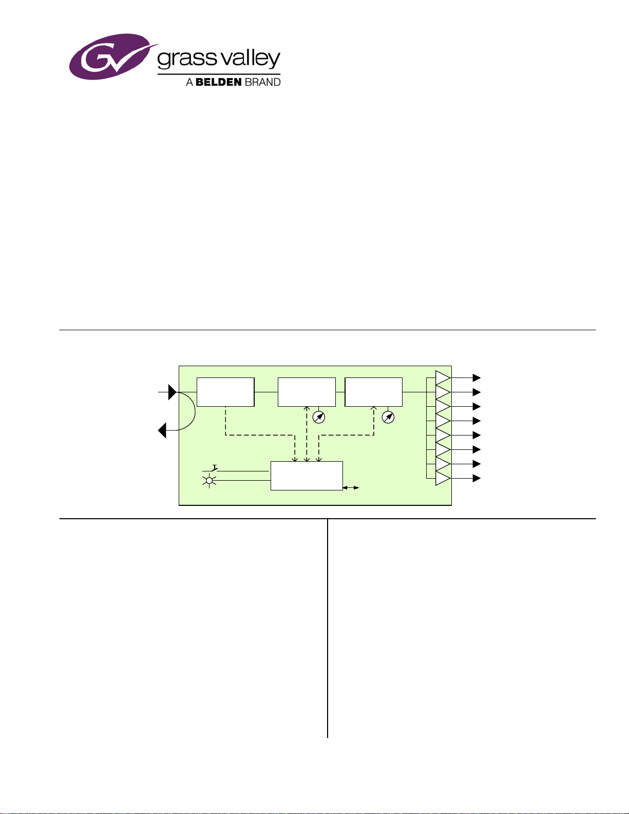
The location of jumpers and trim pots mentioned in these
procedures is shown in this diagram:
1. 100% luma level adjustment
•Connect the 100/75 colour bars signal to the VEA-
1023's input connector situated at the back of the
DENSITÉ frame, through the 100 m cable.
•Connect an output to the measuring equipment.
•Before inserting the VEA-1023 into its slot, place a
jumper over pins 1-2 "G/EQ ADJ" of header LK2.
•Insert card. Wait approximately 10 seconds for the
output to stabilize to the current gain and EQ
adjustments.
The LED is yellow.
Using the measuring equipment to observe the result,
slowly turn the "GAIN CAL" potentiometer (P3) situated
on the card edge to adjust the white level to 100%.
Format
100% white level
NTSC with setup
714 mV or 100 IRE
NTSC no setup
714 mV or 100 IRE
PAL
700 mV
NOTE: The output reacts slowly when the
potentiometer is turned and it is constantly fluctuating
even when the potentiometer is not being turned.
This is normal. The card is continually comparing the
input signal to the potentiometer value.
2. Equalisation adjustment
•Keep the card in the slot.
•Using the measuring equipment to observe the
result, slowly turn the ‘EQ CAL’ potentiometer to
adjust the peak-to-peak level of the red bar in the
100/75 colour bars signal at the output of the VEA-
1023.
Another method is to use a vectorscope and make all
colour vectors converge upon the center of their
respective tight tolerance boxes.
Format
75% p-p red level
NTSC with setup
626 mV or 87.7 IRE
NTSC no setup
677 mV or 94.9 IRE
PAL
664 mV
NOTE: Again, the output reacts slowly when the
potentiometer is turned and it is constantly fluctuating
even when the potentiometer is not being turned. This is
normal. The card is continually comparing the input
signal to the potentiometer value.
When the desired result is attained, remove the VEA-1023
from the slot. The following auto-calibration is
necessary to save these gain and EQ adjustments.
Auto-calibration
This calibration adapts the VEA-1023 to the system. Send
the full-field 100/75 colour bars signal through the system
to correct the attenuation caused by cable length.
After removing the VEA-1023 from the slot, there are
three ways to perform an auto-calibration. First, remove
the jumper over pins 1-2 of LK2. Then,

VEA-1023 Analog Video Auto Equalizing DA
Guide to Installation and Operation
VEA-1023 Page 5 of 5
Without (DENSITÉ) controller: place the jumper over pins
3-4 "AUTO-CAL" of LK2. Insert the card. The LED is
yellow. The calibration starts after 2 s, wait
approximately 20 seconds for the LED to return green.
Remove the card and place the jumper over pins 5-6
"NORMAL" of LK2 and insert the card.
With (DENSITÉ) controller: place the jumper over pins 5-
6 "NORMAL" of LK2. Insert the card. Wait for the LED
to become green. Enter the VEA-1023's menu by
pressing the Select button on the card edge. With the
chassis controller, from "STATUS" press [-], from
"CALIBRATION" press [SELECT], from
"AUTOCALIBRATION" press [SELECT], from "START"
press [SELECT], then "AUTOCALIBRATING" will
appear. The auto-calibration ends with either
"SUCCESS" or "OUT OF RANGE". If out of range,
there is no input signal or the correction needed is out
of the VEA-1023's range. Check the input signal.
With iControl: Select auto-calibration and wait for the
result. If the result is "OUT OF RANGE”, there is no
input signal or the correction needed is out of the VEA-
1023's range. Check the input signal.
The VEA-1023 is now calibrated and ready for use.
NOTE: The "GAIN ADJ" and "EQ ADJ" potentiometers are
used to set the reference gain and equalization levels.
These levels are used during the auto-calibration process.
Hence, turning the potentiometers while in normal mode
(jumper on pins 5-6 "NORMAL" of LK2) will have no
immediate effect. The effect will be seen only after the next
auto-calibration. If this happens, the First-time Calibration
and Auto-calibration procedures described above must be
redone.
NOTE: if you push on the Select button during the
calibration, until the led returns green, the final value
will replace the factory default value.
According to the video input signal, NTSC or PAL, the card
will store two different factory default values: one for
NTSC and one for PAL.
Clamp Settings
The degree of clamping applied to the input signal can be
adjusted using the jumper LK1 (see the figure on page 4
for its location)
Jumper position Degree of clamping
1 – 2 None
3 – 4 Hard
5 – 6 Soft
COMPLIANCE Radio Frequency Interference and Immunity
This unit generates, uses, and can radiate radio frequency energy. If the unit is not properly installed and used in accordance
with this guide, it may cause interference with radio communications. Operation with non-certified peripheral devices is likely to
result in interference with radio and television reception. This equipment has been tested and complies with the limits in
accordance with the specifications in:
FCC Part 15, Subpart B; CE EN50081-1:1992; CE EN50082-1:1992.
Grass Valley Technical Support
For technical assistance, contact our international support center, at:
1-800-547-8949 (US and Canada) or +1 530 478 4148.
To obtain a local phone number for the support center nearest you, please consult the Contact Us section of Grass Valley’s
website (www.grassvalley.com).
An online form for e-mail contact is also available from the website.
Corporate Head Office
Grass Valley
3499 Douglas-B.-Floreani
St-Laurent, Quebec H4S 2C6
Canada
Telephone: +1 514 333 1772
Fax: +1 514 333 9828
www.grassvalley.com
Table of contents
Other Belden Amplifier manuals

Belden
Belden Grass Valley HDA-1911 Instruction Manual

Belden
Belden PPC Entry Series User manual

Belden
Belden Grass Valley DDA-1133 Instruction Manual

Belden
Belden grass valley IQSDA41 Series User manual

Belden
Belden GRASS VALLEY HDA-1941 Instruction Manual

Belden
Belden GRASS VALLEY HDA-3961 Instruction Manual

Belden
Belden GRASS VALLEY HDA-3911 Instruction Manual