Belden Grass Valley HDA-1911 Instruction Manual

HDA-1911/1931
Single/Dual 3Gbps HD-SDI Distribution Amplifiers
Guide to Installation and Operation
M873-9900-103
2019-06-20
.

GUIDE TO INSTALLATION AND OPERATION
2| HDA-1911/1931
Copyright and Trademark Notice
Copyright © 2009-2019, Grass Valley Canada. All rights reserved.
Belden, Belden Sending All The Right Signals, and the Belden logo are trademarks or registered trademarks of
Belden Inc. or its affiliated companies in the United States and other jurisdictions. Grass Valley, Miranda, HDA-1911,
HAD-1931, iControl, and Densité are trademarks or registered trademarks of Grass Valley Canada. Belden Inc.,
Grass Valley USA, LLC, and other parties may also have trademark rights in other terms used herein.
Product Patents
This product may be protected by one or more patents. For further information, please visit:
www.grassvalley.com/patents/
Terms and Conditions
Please read the following terms and conditions carefully. By using HDA-1911 / HAD-1931 documentation, you agree
to the following terms and conditions.
Grass Valley hereby grants permission and license to owners of HDA-1911 / HAD-1931 to use their product manuals
for their own internal business use. Manuals for Grass Valley products may not be reproduced or transmitted in any
form or by any means, electronic or mechanical, including photocopying and recording, for any purpose unless
specifically authorized in writing by Grass Valley.
A Grass Valley manual may have been revised to reflect changes made to the product during its manufacturing life.
Thus, different versions of a manual may exist for any given product. Care should be taken to ensure that one obtains
the proper manual version for a specific product serial number.
Information in this document is subject to change without notice and does not represent a commitment on the part of
Grass Valley.
Warranty information is available in the Support section of the Grass Valley Web site (www.grassvalley.com).

GUIDE TO INSTALLATION AND OPERATION
HDA-1911/1931 | 3
Electromagnetic Compatibility
This equipment has been tested for verification of compliance with FCC Part 15, Subpart B requirements for
Class A digital devices.
NOTE: This equipment has been tested and found to comply with the limits for a Class A digital device, pursuant to
part 15 of the FCC Rules. These limits are designed to provide reasonable protection against harmful interference
when the equipment is operated in a commercial environment. This equipment generates, uses, and can radiate
radio frequency energy and, if not installed and used in accordance with the instruction manual, may cause harmful
interference to radio communications. Operation of this equipment in a residential area is likely to cause harmful
interference in which case the user will be required to correct the interference at his own expense.
This equipment has been tested and found to comply with the requirements of the EMC directive
2004/108/CE:
EN 55022 Class A radiated and conducted emissions
EN 55024 Immunity of Information Technology Equipment
EN 61000-3-2 Harmonic current injection
EN 61000-3-3 Limitation of voltage changes, voltage fluctuations and flicker
EN 61000-4-2 Electrostatic discharge immunity
EN 61000-4-5 Surge immunity
EN 61000-4-11 Voltage dips, short interruptions and voltage variations immunity

GUIDE TO INSTALLATION AND OPERATION
4| HDA-1911/1931
Table of Contents
1HDA Single/Dual 3 Gbps HD-SDI Distribution Amplifiers ...................................................... 5
1.1 Introduction..........................................................................................................................................5
1.2 Features...............................................................................................................................................5
1.3 Block Diagrams ...................................................................................................................................5
1.4 Front Card-edge Interface...................................................................................................................6
2Installation.................................................................................................................................. 7
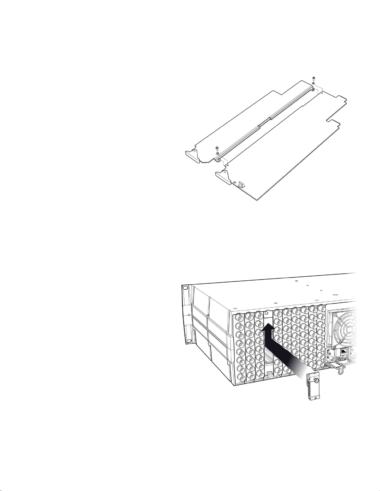
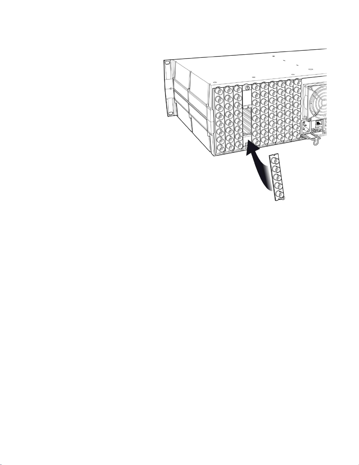
2.1 Installation of Rear Connector Panels.................................................................................................7
2.2 Card Installation...................................................................................................................................8
2.3 Installing Densité-2 Cards and Rear Modules in a Densité-3 Frame..................................................8
2.4 Signal Connections on Rear Connector Panels................................................................................10
2.5 Rear Panel Configurations ................................................................................................................11
3Operation.................................................................................................................................. 14
3.1 Control Options..................................................................................................................................14
3.2 Card-Edge Status LED......................................................................................................................14
3.3 Local control using the Densité frame control panel.........................................................................15
3.3.1 Overview...............................................................................................................................15
3.3.2 Menu for local control...........................................................................................................15
3.4 Remote control using iControl...........................................................................................................16
3.4.1 The iControl graphic interface window.................................................................................16
3.4.2 The Input panel.....................................................................................................................18
3.4.3 The Rear panel.....................................................................................................................19
3.4.4 The Status panel ..................................................................................................................19
3.4.5 The Output panel..................................................................................................................20
3.4.6 The Alarms panel .................................................................................................................21
3.4.7 The Info panel.......................................................................................................................23
3.4.8 The Presets panel ................................................................................................................25
4Specifications .......................................................................................................................... 26
5Contact Us................................................................................................................................ 27
Grass Valley Technical Support.................................................................................................................27
Corporate Head Office................................................................................................................................27
ANNEX 1 –HDA-1911/1931 Local User Interface........................................................................ 28
ANNEX 2 –Installing the Optical Interface.................................................................................. 30

GUIDE TO INSTALLATION AND OPERATION
HDA-1911/1931 | 5
1 HDA Single/Dual 3 Gbps HD-SDI Distribution Amplifiers
1.1 Introduction
The HDA-1911/1931 is a 3Gbps HD-SDI video DA supporting a variety of compressed and uncompressed serial
digital video signals. The HDA-1911/1931 provides 9 reclocked outputs with automatic equalization for up to 140
meters of cable (Belden 1694A) at 1.485 Gbps and up to 90 meters at 2.97 Gbps. The HDA-1931 also offers the
added benefit of implementing a dual 1x4 amplifier instead of a single 1x9.
When longer cable lengths are required, the HDA-1911/1931 are ideal since they can natively offer fiber connectivity.
Additional protection for critical applications is provided by an optional protection bypass relay available on selected
rears.
The HDA-1911/1931 will also support DVB-ASI on selected outputs.
1.2 Features
One or two inputs
Up to 9 3Gbps HD-SDI outputs
Supports bit-rates all the way up to 2.97 Gbps
Maximum flexibility offered by three operation modes: single 1x9, single 1x4, and dual 1x4 (HDA-1931) within
Densite-2
Automatic format detection and cable equalization
Optional fiber I/O
Optional bypass relay protection
DVB-ASI format is also supported (not on all outputs –see rear panel drawings in Fig. 2.1 for details)
MSB support
1.3 Block Diagrams
Figure 1.1(a) HDA-1911 Functional Block Diagram

GUIDE TO INSTALLATION AND OPERATION
6| HDA-1911/1931
Figure 1.1(b)HDA-1931 Functional Block Diagram
1.4 Front Card-edge Interface
The front card-edge of the HDA-19x1 incorporates two
elements:
Status LED (see section 3.2)
Select Button (see section 3.3)
Figure 1.2 Front card-edge layout
Select
Status
Status LED
SELECT button
HDA-19x1

GUIDE TO INSTALLATION AND OPERATION
HDA-1911/1931 | 7
2 Installation
2.1 Installation of Rear Connector Panels
Miranda Densité-series cards are each associated with a rear connector panel, which must be installed in the Densité
frame before the card can be inserted.
The HDA-19x1 card is sized to fit into Miranda’s Densité-2 frame. Eight different rear connector panels are available
to fit the Densité 2 frame:
HDA-19NN-SRP Single rear for 1x4 operating mode.
HDA-19NN-SRP-R Single rear for 1x4 operating mode with bypass protection relay.
HDA-19NN-SRP-F Single rear for 1x2 operating mode with fiber option support.
HDA-19NN-DRP Double rear for 1x9 operating mode.
HDA-19NN-DRP-R Double rear for 1x9 operating mode with bypass protection relay.
HDA-19NN-DRP-F Double rear for 1x8 operating mode with fiber option support.
HDA-193N-DRP Double rear for dual 1x4 operating mode (HDA-1931 only).
HDA-193N-DRP-F Double rear for dual 1x3 operating mode with fiber option support (HDA-1931 only).
With the use of an available adapter (Densité 3 –EXT B), the HDA-19x1 can also be installed in a Densité-3 frame
(see section 2.3 below). Two rear connector panels for this frame are available for the HDA-19x1:
HDA-191N-3SRP Single rear for 1x7 operating mode.
HDA-193N-3SRP Single rear for dual 1x3 operating mode (HDA-1931 only).
The eight Densité-2 rear panels can also be used in a Densité-3 frame, with the addition of available adapters:
HDA-19NN-SRP + DENSITE-SRP-3RU Single rear for 1x4 operating mode.
HDA-19NN-SRP-R + DENSITE-SRP-3RU Single rear for 1x4 operating mode with bypass protection relay.
HDA-19NN-SRP-F + DENSITE-SRP-3RU Single rear for 1x2 operating mode with fiber option support.
HDA-19NN-DRP + DENSITE-DRP-3RU Double rear for 1x9 operating mode.
HDA-19NN-DRP-R + DENSITE-DRP-3RU Double rear for 1x9 operating mode with bypass protection relay.
HDA-19NN-DRP-F + DENSITE-DRP-3RU Double rear for 1x8 operating mode with fiber option support.
HDA-193N-DRP + DENSITE-DRP-3RU Double rear for dual 1x4 operating mode (HDA-1931 only).
HDA-193N-DRP-F + DENSITE-DRP-3RU Double rear for dual 1x3 operating mode with fiber option
support (HDA-1931 only).
All cards and rear panels can be installed with the frame power on. The card has connectors which plug into a mid-
frame mother board for distribution of power and for connection to the controller card, and a second connector which
plugs directly into the rear connector panel for input and output.

GUIDE TO INSTALLATION AND OPERATION
8| HDA-1911/1931
The rear connector panel must be installed with the card out of the frame.
To remove an existing card from the slot, tilt up the swivel handle on the front of the card to lever the connectors
apart, then use the handle to pull the card straight out of the slot.
Densité-2 frame –rear panel installation Densité-3 frame –rear panel installation
To install the connector panel:
(NOTE - if you are installing a Densité-2 rear panel plus adapter in a Densité-3 frame, please go to section 2.3)
1. If a card is installed in the slot whose rear panel is being changed, remove it as described above.
2. Remove the existing panel (either blank or belonging to an existing card that is being changed) by releasing the
captive screw(s) at the bottom.
3. Position the new panel and secure it in place with the captive screw(s) at the bottom.
2.2 Card Installation
Once a matching rear connector panel has been installed, install the HDA-19x1 card as follows:
1. Open the front panel of the frame.
2. Slide the HDA-19x1 card into the slot and push gently on the handle to seat the connectors.
If the card is used with a double-width rear panel (DRP), it should be inserted into the right-hand slot. Inserting
the card into the wrong slot will not damage the card, and will be flagged by the on-card status LED flashing red
to indicate that there is no connection to the rear panel.
3. Close the front panel of the frame.
2.3 Installing Densité-2 Cards and Rear Modules in a Densité-3 Frame
The Densité-3 frame supports many Miranda Densité-2 series cards, including the HDA-19x1. Should you wish to
install the HDA-19x1 card in your Densité-3 frame, you will need an adapter for the card. You may use one of the two
3 RU rear panels that are available for the HDA-19x1 (3SRP), or you may use one of the eight 2 RU rear panels. In

GUIDE TO INSTALLATION AND OPERATION
HDA-1911/1931 | 9
the latter case, an adapter will also be required for the rear panel, as described above. These adapters extend the
height of the Densité-2 devices so that they will fit into the slots of the 3 RU Densité-3 frame.
Card adapters:
There are 3 different types of adapters available,
depending on the Densité 2 card geometry, so be
sure to order the adapter designed to fit the HDA-
19x1 card.
Densité 3 –EXT B
Install the adapter on the HDA-19x1 as follows:
1. Fit the top edge of the card into the holding
slot along the bottom edge of the adapter.
2. Align the holes in the top of the card with the
holes on the adapter, and secure them
together with the two provided screws and
lock washers, as shown in the figure.
Rear adapters:
3-RU rear module adapters are available for Densité-2 rear panels:
oDENSITE-SRP-3RU for single-slot-width rear panels
oDENSITE-DRP-3RU for double-slot-width rear panels
Install these as follows:
1. Position the adapter at the top of the empty
slot(s) on the rear of the frame.
2. Use the captive screw in the adapter to
fasten it securely in position.

GUIDE TO INSTALLATION AND OPERATION
10 | HDA-1911/1931
3. Slip the top of the 2RU rear panel into the slot
at the bottom of the adapter, and secure it to
the frame using the captive screw at the
bottom of the panel.
2.4 Signal Connections on Rear Connector Panels
Ten rear panels are available for the HDA-19x1. Panels are available for the Densité 2RU frame, and also for the
Densité 3RU frame. The 3RU versions are identified by the number 3 in the size designator portion of the part
number, e.g.
HDA-19x1-SRP is a 2RU version
HDA-19x1-3SRP is a 3RU version
The panel layouts and connectors are illustrated in section 2.5.
The connectors and signal types are the same for all rear types, and are as follows:
HD SDI IN –serial digital HD/SD input
Connect a serial digital video signal, conforming to the SMPTE 292M standard for HD input signals or SMPTE 259M
standard for SD input signals, to the BNC labeled HD SDI IN. DVB-ASI is also supported. The HDA-19x1 will
automatically switch to the detected video line format.
HD SDI OUT –serial digital video outputs
The HDA-19x1 provides multiple HD/SD SDI video outputs on BNC connectors, labeled HD SDI OUT 1,2, etc. The
SDI video signal conforms to the SMPTE 292M and SMPTE 259M-C standard. Not all outputs support DVB-ASI –see
the note on page 13.
Fiber I/O connector
SFP optical modules are small, hot-pluggable cartridges which provide fiber connectivity to the HDA-1911/1931
distribution amplifiers. By using fiber instead of coaxial cable, these interfaces can be used over much longer
distances without impacting signal quality.

GUIDE TO INSTALLATION AND OPERATION
HDA-1911/1931 | 11
SFP Modules can be installed into HDA-1911/1931 rear panels that offer SFP video connectivity, easily identifiable by
an -F extension in the Miranda Rear part number. A single SFP optical module offers either 1 or 2 fiber connections,
available as single Tx or Rx, dual Rx or Tx or as a bidirectional Rx/Tx. Dual Rx or Dual Tx on single fiber can be
achieved with the WDM SFP modules.
The fiber I/O connector accepts any of the available SFP cartridges. At the time of publication of this document, the
following cartridges were available:
SFP-R-LC Single fiber Rx (input) cartridge with LC/PC connector
SFP-RR-LC Dual fiber Rx (input) cartridge with LC/PC connector
SFP-T-S13-LC Single fiber Tx (output) cartridge at 1310 nm with LC/PC connector
SFP-TT-S13S13-LC Dual fiber Tx (output) cartridge at 1310 nm with LC/PC connector
SFP-RT-S13-LC Dual fiber Rx/Tx (input/output) cartridge at 1310 nm with LC/PC connector
SFP-RR-W-LC Single fiber dual Rx (2 inputs) cartridge with WDM - LC/PC connector
SFP-TT-W13W15-LC Single fiber dual Tx (2 outputs) cartridge at 1310 and 1550 nm with WDM - LC/PC
SFP-TT-CxxCyy-LC Dual optical CWDM Tx cartridge, xx/yy nm with LC/PC connector
SFP-THTH-CxxCyy-LC Dual optical hi-power CWDM Tx cartridge, xx/yy nm with LC/PC connector
Note –for CWDM cartridges, xx and yy are the wavelengths of the two lasers.
Insert the appropriate cartridge for your application into the Fiber I/O connector, and then connect the fibers to the
cartridge via the LC connectors.
See ANNEX 2 on page 30 for a detailed description of the installation & removal procedure.
2.5 Rear Panel Configurations
The following diagrams illustrate the layout and connectors on the available HDA-19x1 rear panels. Note that the
HDA-19x1’s functionality is determined by the rear panel that is installed
HDA-19NN-SRP Single rear for 1x4 operating mode.
HDA-19NN-SRP-R Single rear for 1x4 operating mode with bypass protection relay.
HDA-19NN-SRP-F Single rear for 1x2 operating mode with fiber option support.

GUIDE TO INSTALLATION AND OPERATION
12 | HDA-1911/1931
HDA-19NN-DRP Double rear for 1x9 operating mode.
HDA-19NN-DRP-R Double rear for 1x9 operating mode with bypass protection relay.
HDA-19NN-DRP-F Double rear for 1x8 operating mode with fiber option support.
HDA-193N-DRP Double rear for dual 1x4 operating mode (HDA-1931 only).

GUIDE TO INSTALLATION AND OPERATION
HDA-1911/1931 | 13
HDA-193N-DRP-F Double rear for dual 1x3 operating mode with fiber option support (HDA-1931 only).
HDA-191N-3SRP Single rear for 1x7 operating mode.
HDA-193N-3SRP Single rear for dual 1x3 operating mode (HDA-1931 only).
This table summarizes the input/output connections on the various rear panels shown above:
I/O Connections
Use with
Rear panel type
HD-SDI IN
HD-SDI OUT
FIBER I/O
Bypass
HDA-1911
HDA-1931
Densité-2 panels
HDA-19NN-SRP
1
4
HDA-19NN-SRP-R
1
4
HDA-19NN-SRP-F
1
2
HDA-19NN-DRP
1
9
HDA-19NN-DRP-R
1
9
HDA-19NN-DRP-F
1
7
HDA-193N-DRP
2
2 x 4
HDA-193N-DRP-F
2
2 x 3
Densité-3 panels
HDA-191N-3SRP
1
7
HDA-193N-3SRP
2
2 x 3
NOTE - The outputs labeled with white letters on a black circle DO NOT support ASI output

GUIDE TO INSTALLATION AND OPERATION
14 | HDA-1911/1931
3 Operation
3.1 Control Options
The HDA-19x1 can be controlled in two different ways:
The local control panel and its push-buttons can be used to move through a menu of parameters and to adjust
parameter values (see section 3.3).
Miranda’s iControl system can be used to access the card’s operating parameters from a remote computer, using
a convenient graphical user interface (GUI). (see section 3.4)
3.2 Card-Edge Status LED
The status monitor LED is located on the front card-edge of the HDA-19x1, and is visible through the front access door
of the DENSITÉ frame. This multi-color LED indicates the status of the HDA-19x1 by color, and by flashing/steady
illumination.
The chart shows how the various error conditions that can be flagged on the HDA-19x1 affect the LED status.
If a cell is gray, the error condition cannot cause the LED to assume that status
If more than one LED status is possible for a particular error condition, the status is configurable.
See Section 0 for details.
The factory default status is shown by a
The LED will always show the most severe detected error status that it is configured to display, and in the chart error
severity increases from left to right, with green representing no error/disabled, and flashing red the most severe error.
LED Status
Error Condition
Green
Yellow
Red
Flashing
Red
No input signal presence
No lock on input signal
No fiber present when needed
No rear
: Factory default.
If the LED is Flashing Yellow, it means that the card is selected for local control using the Densité frame’s control
panel. See Section 3.3 for details.
The LED will be Yellow when the card is in the “Firmware Update” mode.

GUIDE TO INSTALLATION AND OPERATION
HDA-1911/1931 | 15
3.3 Local control using the Densité frame control panel
3.3.1 Overview
Push the SELECT button on the HDA-19x1 card edge (see Section 1.4) to assign the local control panel to operate
the HDA-19x1. Use the control panel buttons to navigate through the menu, as described below.
All of the cards installed in a Densité frame are connected to the frame’s controller card, which handles all interaction
between the cards and the outside world. There are no operating controls located on the cards themselves. The
controller supports remote operation via its Ethernet ports, and local operation using its integrated control panel.
The local control panel is fastened to the controller
card by a hinged connector, and when installed is
located in the front center of the frame, positioned in
front of the power supplies. The panel consists of a
display unit capable of displaying two lines of text,
each 16 characters in length, and five pushbuttons.
The panel is assigned to operate any card in the
frame by pushing the SELECT button on the front
edge of that card.
Figure 3.1 Densité Frame local control panel
Pushing the CONTROLLER button on the control panel selects the Controller card itself.
The STATUS LED on the selected card flashes yellow.
The local control panel displays a menu that can be navigated using the four pushbuttons located beneath the
display. The functionality of the pushbuttons is as follows:
[+] [–] Used for menu navigation and value modification
[SELECT] Gives access to the next menu level. When a parameter value is shown, pushing this button once
enables modification of the value using the [+] and [–] buttons; a second push confirms the new value
[ESC] Cancels the effect of parameter value changes that have not been confirmed; pushing [ESC] causes the
parameter to revert to its former value.
Pushing [ESC] moves the user back up to the previous menu level. At the main menu, [ESC] does not
exit the menu system. To exit, re-push the [SELECT] button for the card being controlled.
If no controls are operated for 30 seconds, the controller reverts to its normal standby status, and the selected card’s
STATUS LED reverts to its normal operating mode.
3.3.2 Menu for local control
The HDA-19x1 has operating parameters which may be adjusted locally at the controller card interface.
Press the SELECT button on the HDA-19x1 front card edge to assign the Densité frame’s local control panel
to the HDA-19x1
Use the keys on the local control panel to step through the displayed menu to configure and adjust the HDA-
19x1.
The complete menu structure is shown in Annex 1 to this document, beginning on page 27.
SELECT
ESC +
-
CONTROLLER

GUIDE TO INSTALLATION AND OPERATION
16 | HDA-1911/1931
3.4 Remote control using iControl
The operation of the HDA-19x1 may be controlled using Miranda’s iControl system.
This manual describes the control panels associated with the HDA-19x1 and their use.
Please consult the iControl User’s Guide for information about setting up and operating iControl.
Exception: At the time of printing, the HDA-19x1 was not supported by iControl Solo
In iControl Navigator or iControl Websites, double-click on the HDA-19x1 icon to open the control panel.
3.4.1 The iControl graphic interface window
The basic window structure for the HDA-19x1 is shown in figure 3.2. The window identification line gives the card type
(HDA-1911 or HDA-1931) and the slot number where the card is installed in its Densité frame.
Figure 3.2 HDA-1931 iControl graphic interface window:
There are three main sections in the window itself, shown in Figure 3.2:
1. The top section displays icons on the left. These icons report the
status of some parameters associated with this HDA-19x1. Figure 3.3
shows the three icons that appear.
Move the mouse over an icon and a status message appears below the
icon providing additional information.
If there is an error, the error status message appears in the message
area without mouse-over.
If there are multiple errors, the error messages cycle
The icon whose status or error message is shown is highlighted
with a mauve background
Icon # 1 2 3
Figure 3.3 iControl Status Icons
1
2
3

GUIDE TO INSTALLATION AND OPERATION
HDA-1911/1931 | 17
The table below lists the various status icons that can appear, and how they are to be interpreted.
In cases where there is more than one possible interpretation, read the error message in the iControl window to
see which applies.
Table –iControl Status Icon interpretation
Icon #1 –Manual Card Configuration
(green)
Remote card control activated. The iControl interface can be used to operate the card
(yellow)
Local card control active, The card is being controlled using the Densité frame control
panel, as described in section 3.3. Any changes made using the iControl interface will have
no effect on the card.
Icon #2 –Input A status
(green)
Signal detected and valid.
Beneath the icon, the format will be indicated as HD or SD, and the specific format
details will be listed if the cursor is moved over the icon.
(red)
Input signal error
No rear
(grey)
No electrical input
Icon #3 –Input B status
(green)
Signal detected and valid.
Beneath the icon, the format will be indicated as HD or SD, and the specific format
details will be listed if the cursor is moved over the icon.
(red)
Input signal error
No rear
(grey)
No electrical input
2. The center portion of the iControl graphic interface window contains a series of control and information panels,
selected by tabs.
Click on a tab to display the associated panel.
Each of these panels is described individually in the following sections.

GUIDE TO INSTALLATION AND OPERATION
18 | HDA-1911/1931
3. The Load Factory button is always visible at the bottom of the panel. Click the Load Factory button to reset all
parameters on this HDA-19x1 card to factory default values.
The factory default values are shown underlined in the menus found in the Annex to this document, beginning
on page 27.
3.4.2 The Input panel
This panel allows the user to
select the input that will be
processed through the
available channels in the
HDA-19x1.
HDA-1911: Only one channel
is available, so
channel B does
not appear in the
panel
HDA-1931: Two channels are
available. The
rear panel may
have one or two
electrical inputs,
and may have
two optical inputs.
Channel B will be
greyed out if no
signal is available
for it.
Input Config
Select the input for Channel A and Channel B, using the radio buttons.
Electrical Input A and Optical Input A can only go to Channel A
Electrical Input B can only go to Channel B
Optical Input B can go to either Channel A or Channel B
Reclocker
Use the radio buttons to independently turn the reclockers for Channels A and B ON or OFF
Figure 3.4 Input panel –HDA-1911 (left) and HDA-1931 (right)

GUIDE TO INSTALLATION AND OPERATION
HDA-1911/1931 | 19
3.4.3 The Rear panel
This panel identifies the type of rear panel installed with this HDA-19x1.
The name of the installed rear panel appears in the data box.
If no rear is installed, “No Rear” appears in the data box.
3.4.4 The Status panel
This panel shows the status of the various inputs to this HDA-19x1.
For HDA-1911, only IN A is shown, because there is no IN B,
Electrical inputs (A and B)
Data rate (270 Mbps / 1.5 Gbps / 3 Gbps) –the detected input data rate is
indicated by a green status icon
No Lock / No Signal –either of these conditions is indicated by a red
status icon
Fiber
Module type: the type of fiber module installed in the rear panel will be
shown in the text box:
None
Single RX
Single TX
Dual RX
Dual TX
Bidirectional
Figure 3.5 Rear panel
Figure 3.6 Status panel

GUIDE TO INSTALLATION AND OPERATION
20 | HDA-1911/1931
Figure 3.7 Output panel –Single
Channel Operating Mode
3.4.5 The Output panel
This panel controls the optical
output functions (when
equipped; see the Status tab)
related the HDA-19x1 output:
Output Config
If an optical output is available,
use the radio buttons to
independently turn the two
optical outputs OFF or ON:
Optical output is only
available for rear panels
with a Fiber I/O
connector and an
installed single or dual
output (TX) cartridge
Optical output A, can
only carry channel A
On an HDA-1931, optical
output B can carry
Channel A when the
Operating Mode is set to
Single Channel (see the
Input tab), or it carries
Channel B when the
Operating Mode is set to
Dual Channel
On an HDA-1911, only optical output A can be configured. With a dual output (TX) cartridge, channel A is made
available at both optical outputs A and B
MSB Output
Use the radio buttons to select which of the two channels in the HDA-1931 will be sent to the Monitoring Switching
Bridge (if present) in the Densité frame.
This does not appear on the HDA-1911 as there is only one channel and as such, no choice is necessary.
Figure 3.8 Output panel –Dual
Channel Operating Mode
This manual suits for next models
1
Table of contents
Other Belden Amplifier manuals

Belden
Belden PPC Entry Series User manual

Belden
Belden grass valley IQSDA41 Series User manual

Belden
Belden GRASS VALLEY HDA-3961 Instruction Manual

Belden
Belden Grass Valley VEA-1023 Instruction Manual

Belden
Belden Grass Valley DDA-1133 Instruction Manual

Belden
Belden GRASS VALLEY HDA-3911 Instruction Manual

Belden
Belden GRASS VALLEY HDA-1941 Instruction Manual