Belden GRASS VALLEY HDA-3961 Instruction Manual

HDA-3961
Single/Dual 12G/3G/HD/SD SDI Distribution
Amplifier (DA) with Optional Fiber Connectivity
Guide to Installation and Operation
13-03070-010-AA-M00
2019-01-28

GUIDE TO INSTALLATION AND OPERATION
2| HDA-3961
Electromagnetic Compatibility
This equipment has been tested for verification of compliance with FCC Part 15, Subpart B requirements for
Class A digital devices.
NOTE: This equipment has been tested and found to comply with the limits for a Class A digital device, pursuant to
part 15 of the FCC Rules. These limits are designed to provide reasonable protection against harmful interference
when the equipment is operated in a commercial environment. This equipment generates, uses, and can radiate
radio frequency energy and, if not installed and used in accordance with the instruction manual, may cause harmful
interference to radio communications. Operation of this equipment in a residential area is likely to cause harmful
interference in which case the user will be required to correct the interference at his own expense.
This equipment has been tested and found to comply with the requirements of the EMC directive
2004/108/CE:
EN 55022 Class A radiated and conducted emissions
EN 55024 Immunity of Information Technology Equipment
EN 61000-3-2 Harmonic current injection
EN 61000-3-3 Limitation of voltage changes, voltage fluctuations and flicker
EN 61000-4-2 Electrostatic discharge immunity
EN 61000-4-5 Surge immunity

GUIDE TO INSTALLATION AND OPERATION
HDA-3961 | 3
Table of Contents
1HDA-3961 Single/Dual 12G/3G/HD/SD SDI Distribution Amplifiers....................................... 4
1.1 Introduction ......................................................................................................................................... 4
1.2 Features.............................................................................................................................................. 4
1.3 Block Diagrams................................................................................................................................... 4
1.4 Front Card-edge Interface................................................................................................................... 5
2Installation.................................................................................................................................. 6
2.1 Installation of Rear Connector Panels................................................................................................ 6
2.2 Card Installation.................................................................................................................................. 6
2.3 Rear Connector Panels....................................................................................................................... 7
3Operation.................................................................................................................................... 8
3.1 Control Options................................................................................................................................... 8
3.2 Card-Edge Status LED ....................................................................................................................... 8
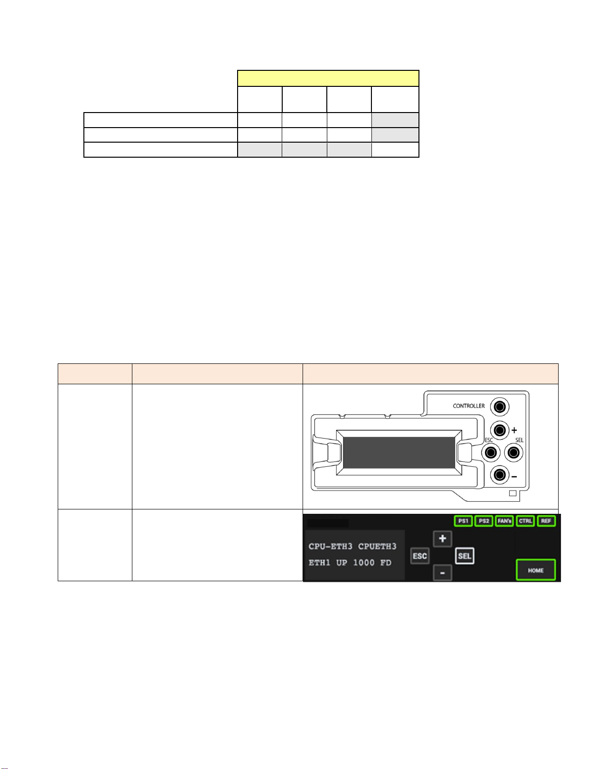
4Local Control Using the Frame’s Control Panel ..................................................................... 9
5Remote Control Using iControl .............................................................................................. 10
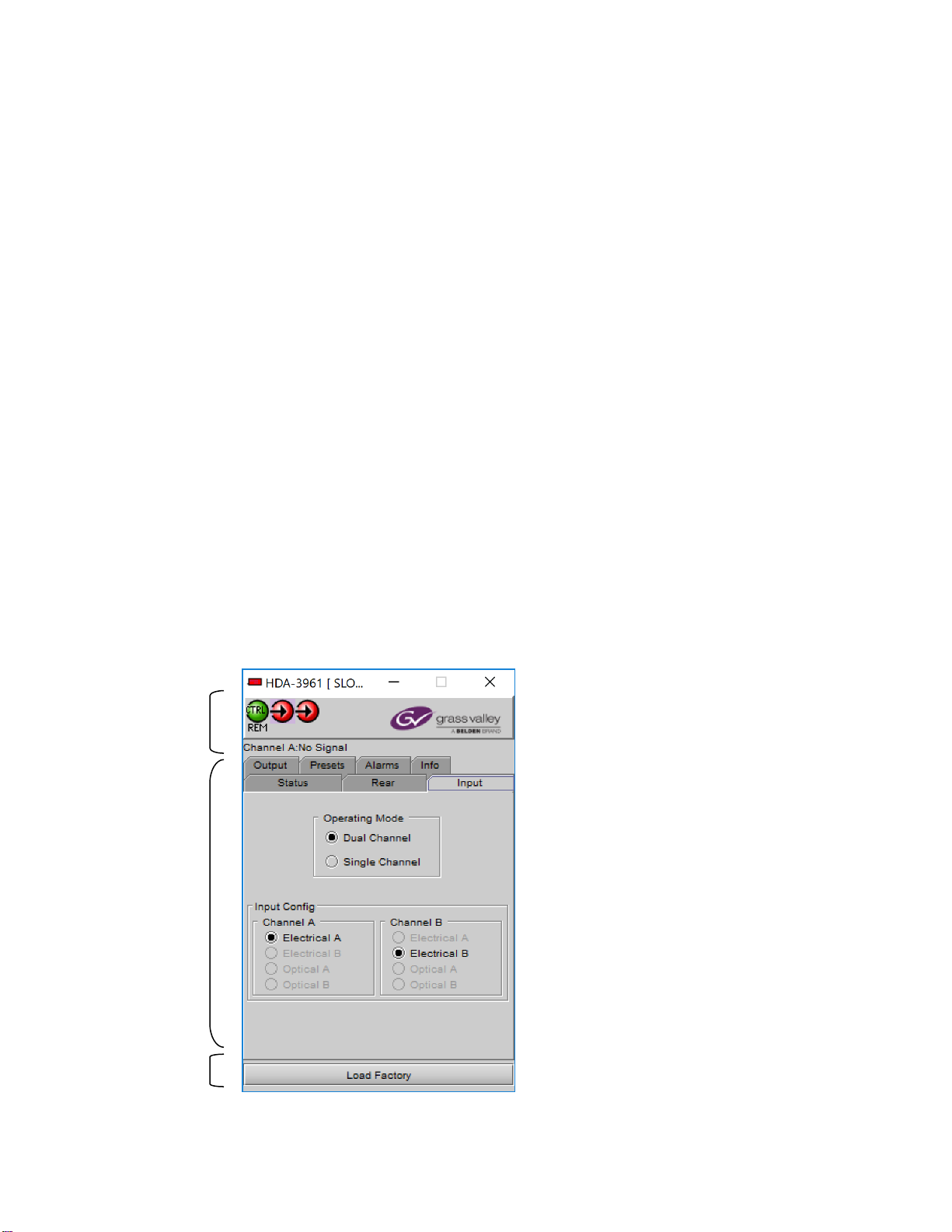
5.1 The iControl Graphic Interface Window............................................................................................ 10
5.2 The Input panel................................................................................................................................. 12
5.3 The Rear panel ................................................................................................................................. 13
5.4 The Status panel............................................................................................................................... 13
5.5 The Output panel.............................................................................................................................. 14
5.6 The Alarms panel.............................................................................................................................. 14
5.7 The Info panel................................................................................................................................... 17
5.8 The Presets panel............................................................................................................................. 19
6Specifications........................................................................................................................... 20
7Contact Us................................................................................................................................ 21
Grass Valley Technical Support................................................................................................................. 21
Corporate Head Office............................................................................................................................... 21
ANNEX 1 –HDA-3961 Local User Interface................................................................................. 22
ANNEX 2 –Installing the Optical Interface.................................................................................. 23

GUIDE TO INSTALLATION AND OPERATION
4| HDA-3961
1 HDA-3961 Single/Dual 12G/3G/HD/SD SDI Distribution Amplifiers
1.1 Introduction
The HDA-3961 from Grass Valley, a Belden Brand, provides single and dual channel distribution for 12G/3G/HD/SD-SDI
signals with flexible routing of inputs to outputs. Flexible output selection enables the HDA-3961 to be used either as a single
channel DA with up to 10 outputs, or in dual channel mode with up to five outputs per input.
The HDA-3961 provides up to ten reclocked outputs with automatic cable equalization.
The HDA-3961 offers fiber connectivity, making it ideal for longer cable lengths. The HDA-3961 provides a user-configurable
fiber optic transceiver for bidirectional conversion of 12G, 3G, HD and SD-SDI signals to 1310 nm optical signals. Ideal for
mixed coax and fiber workflows, the HDA- 3961 allows users to configure the inputs and outputs to match their infrastructure
needs.
1.2 Features
Single/dual 12G/3G/HD/SD-SDI inputs
Flexible selection of inputs allows single or dual channel operation
Supports bitrates up to 11.88 Gb/s
Automatic format detection and cable equalization
Up to 6 × 12G/3G/HD/SD-SDI BNC outputs on the HDA-3961-3SRP-2IN rear
Up to 10 × 12G/3G/HD/SD-SDI HD-BNC outputs on the HDA-3961-3SRP-HF rear
Optional fiber I/O on the HDA-3961-3SRP-HF rear
1.3 Block Diagrams
Figure 1.1 HDA-3961 Functional Block Diagram

GUIDE TO INSTALLATION AND OPERATION
6| HDA-3961
2 Installation
2.1 Installation of Rear Connector Panels
The HDA-3961 card is sized to fit into Grass Valley’s Densité 3 frame. Grass Valley Densité-series cards are each
associated with a rear connector panel, which must be installed in the Densité 3 frame before the card can be inserted.
The following rear connector panels are available for the HDA-3961:
HDA-3961-3SRP-HF Single rear panel with single 1×10 or dual 2×5 HD-BNC with fiber option support
HDA-3961-3SRP-2IN Single rear panel with single 1×6 or dual 2×3 BNCs
All cards and rear panels can be installed with the frame power on. The card has connectors which plug into a mid-frame
mother board for distribution of power and for connection to the controller card, and a second connector which plugs directly
into the rear connector panel for input and output.
The rear connector panel must be installed with the card out of the frame.
To remove an existing card from the slot, tilt up the swivel handle on the front of the card to lever the connectors apart,
then use the handle to pull the card straight out of the slot.
Densité 3 frame –rear panel installation
To install the connector panel:
1. If a card is installed in the slot whose rear panel is being changed, remove it as described above.
2. Remove the existing panel (either blank or belonging to an existing card that is being changed) by releasing the
captive screw(s) at the bottom.
3. Position the new panel and secure it in place with the captive screw(s) at the bottom.
2.2 Card Installation
Once a matching rear connector panel has been installed, install the HDA-3961 card as follows:
1. Open the front panel of the frame.
2. Slide the HDA-3961 card into the slot and push gently on the handle to seat the connectors.
Inserting the card into the wrong slot will not damage the card, and will be flagged by the on-card status LED
flashing red to indicate that there is no connection to the rear panel.
3. Close the front panel of the frame.

GUIDE TO INSTALLATION AND OPERATION
HDA-3961 | 7
2.3 Rear Connector Panels
The following diagrams illustrate the layout and connectors on the available HDA-3961 rear panels. Note that the HDA-3961
functionality is determined by the rear panel that is installed.
HDA-3961 Rear Panels:
HDA-3961-3SRP-HF Single rear panel with single 1×10 or dual 2×5 HD-BNC with fiber option support.
HDA-3961-3SRP-2IN Single rear panel with single 1×6 or dual 2×3 BNCs.
This table summarizes the input/output connections on the various rear panels shown above:
I/O Connections
Rear panel type
12G/3G/HD/SD SDI IN
12G/3G/HD/SD SDI OUT
FIBER I/O
HDA-3961-3SRP-HF
2
10
HDA-3961-3SRP-2IN
2
6
12G/3G/HD/SD IN –Serial digital Video Inputs
Connect a serial digital video signal, conforming to the ST 2082-1 for 12G-SDI, ST 424 for 3G-SDI, SMPTE 292M standard
for HD input signals or SMPTE 259M standard for SD input signals, to the BNC labeled 12G/3G/HD SDI IN. The HDA-3961
will automatically switch to the detected video line format.
12G/3G/HD/SD OUT –Serial Digital Video Outputs
The HDA-3961 provides multiple12G/3G/HD/SD SDI video outputs on BNC or HD-BNC connectors, labeled 12G/3G/HD
OUT 1,2, etc. The SDI video signal conforms to the SMPTE 292M and SMPTE 259M-C standard.
Fiber I/O connector
SFP optical modules are small, hot-pluggable cartridges which provide fiber connectivity to the HDA-3961 distribution
amplifiers. By using fiber instead of coaxial cable, these interfaces can be used over much longer distances without
impacting signal quality.
SFP Modules can be installed into HDA-3961 rear panels that offer SFP connectivity, easily identifiable by a -F extension in
the Grass Valley Rear part number. A single SFP optical module offers either 1 or 2 fiber connections, available as single Tx
or Rx, or dual Rx or Tx.
The fiber I/O connector accepts any of the available SFP cartridges. At the time of publication of this document, the following
cartridges were available:

GUIDE TO INSTALLATION AND OPERATION
8| HDA-3961
SFP-U-R-LC 12G Single RX Fiber with LC/PC
SFP-U-RR-LC 12G Dual Rx Fiber with LC/PC
SFP-U-RT-S13-LC 12G Dual Rx/Tx Fiber 1310 nm with LC/PC
SFP-U-T-S13-LC 12G Single Tx Fiber 1310 nm with LC/PC
SFP-U-TT-S13S13-LC 12G Dual Tx Fiber 1310 nm with LC/PC
SFP-R-LC Single fiber RX cartridge with LC/PC connector
SFP-RR-LC Dual fiber Rx cartridge with LC/PC connector
SFP-T-S13-LC Single fiber TX cartridge at 1310 nm with LC/PC connector
SFP-TT-S13S13-LC Dual fiber Tx cartridge at 1310 nm with LC/PC connector
SFP-RT-S13-LC Dual fiber Rx/Tx cartridge 1310 nm with LC/PC connector
Note: The HDA-3961 can also make use of SFP optical plug-in cartridges from the WDM and CWDM series. Other
types of SFP optical plug-in cartridges may be available.
Insert the appropriate cartridge for your application into the Fiber I/O connector, and then connect the fibers to the
cartridge via the LC connectors.
See ANNEX 2 on page 23 for a detailed description of the installation & removal procedure.
3 Operation
3.1 Control Options
The HDA-3961 can be controlled in two different ways:
The local control panel and its push-buttons can be used to move through a menu of parameters and to adjust
parameter values (see section 4).
Grass Valley’s iControl system can be used to access the card’s operating parameters from a remote computer,
using a convenient graphical user interface (GUI). (see section 5)
3.2 Card-Edge Status LED
The status monitor LED is located on the front card-edge of the HDA-3961, and is visible through the front access door
of the DENSITÉ 3 frame. This multi-color LED indicates the status of the HDA-3961 by color, and by flashing/steady
illumination.
The chart shows how the various error conditions that can be flagged on the HDA-3961 affect the LED status.
If a cell is gray, the error condition cannot cause the LED to assume that status
If more than one LED status is possible for a particular error condition, the status is configurable.
See Section 5.6 for details.
The factory default status is shown by a
The LED will always show the most severe detected error status that it is configured to display, and in the chart error
severity increases from left to right, with green representing no error/disabled, and flashing red the most severe error.

GUIDE TO INSTALLATION AND OPERATION
HDA-3961 | 9
LED Status
Error Condition
Green
Yellow
Red
Flashing
Red
No input signal presence
No lock on input signal
No rear
: Factory default.
If the LED is Flashing Yellow, it means that the card is selected for local control using the Densité frame’s control
panel. See Section 4 for details.
The LED will be Yellow when the card is in the “Firmware Update” mode.
4 Local Control Using the Frame’s Control Panel
Push the SELECT button on the HDA-3961 card edge (see Section 1.4) to assign the local control panel to operate
the HDA-3961.
The STATUS LED on the HDA-3961 card edge flashes yellow.
Use the control panel buttons to navigate through the menu, as described below.
The complete menu structure is shown in ANNEX 1 –HDA-3961 Local User Interface on page 22.
Two versions of the local control panel exist:
Panel type
Frame models
Appearance
Physical
Densité-2, Densité-3, Densité-
3+FR1,
Touch screen
Densité 3+FR4, GV Node
The local control panel is fastened to the front of the frame’s controller card.
The physical panel is accessed by opening the front door of the frame.
The touch screen panel is accessed through an aperture in the frame door.
The panel incorporates a display capable of displaying two lines of text, each 16 characters in length, and four
pushbuttons. The functionality of the pushbuttons is as follows:
[+] [–] Used for menu navigation and value modification
HDA-3961

GUIDE TO INSTALLATION AND OPERATION
10 | HDA-3961
[SELECT] Gives access to the next menu level. When a parameter value is shown, pushing this button once
enables modification of the value using the [+] and [–] buttons; a second push confirms the new value
[ESC] Cancels the effect of parameter value changes that have not been confirmed; pushing [ESC] causes the
parameter to revert to its former value.
Pushing [ESC] moves the user back up to the previous menu level. At the main menu, [ESC] does not
exit the menu system. To exit, re-push the [SELECT] button for the card being controlled.
Notes:
1. If you do not touch any buttons on the local control panel, the controller will revert to its normal
standby mode after 30 seconds.
2. If you changed a parameter from the control menu, but have not applied your change (you did not
touch the SEL button on the control panel), once the 30-second timeout has occurred, the
parameters will be confirmed as if you had touched the SEL button
5 Remote Control Using iControl
The operation of the HDA-3961 may be controlled using Grass Valley’s iControl system.
This manual describes the control panels associated with the HDA-3961 and their use.
Please consult the iControl User’s Guide for information about setting up and operating iControl.
In iControl Navigator or iControl Websites, double-click on the HDA-3961 icon to open the control panel.
5.1 The iControl Graphic Interface Window
The basic window structure for the HDA-3961 is shown in figure 3.2. The window identification line gives the card type
(HDA-3961) and the slot number where the card is installed in its Densité frame.
Figure 3.2 HDA-3961 iControl graphic interface window:
1
2
3

GUIDE TO INSTALLATION AND OPERATION
HDA-3961 | 11
There are three main sections in the window itself, shown in Figure 3.2:
1. The top section displays icons on the left. These icons report the
status of some parameters associated with this HDA-3961. Figure 3.3
shows the three icons that may appear.
Move the mouse over an icon and a status message appears below
the icon providing additional information.
If there is an error, the error status message appears in the message
area without mouse-over.
If there are multiple errors, the error messages cycle
The icon whose status or error message is shown is highlighted
with a mauve background
The table below lists the various status icons that can appear, and how they are to be interpreted.
In cases where there is more than one possible interpretation, read the error message in the iControl window to
see which applies.
Table –iControl Status Icon interpretation
Icon #1 –Manual Card Configuration
(green)
Remote card control activated. The iControl interface can be used to operate the card
(yellow)
Local card control active. The card is being controlled using the Densité 3 frame control
panel, as described in section 4. Any changes made using the iControl interface will have
no effect on the card.
Icon #2 –Input A status
(green)
Signal detected and valid.
Beneath the icon, the format will be indicated as 12G, 3G, HD or SD, and the
specific format details will be listed if the cursor is moved over the icon.
(red)
No signal or Input signal error
No rear
Icon #3 –Input B status
(green)
Signal detected and valid.
Beneath the icon, the format will be indicated as 12G, 3G, HD or SD, and the
specific format details will be listed if the cursor is moved over the icon.
(red)
No signal or Input signal error
No rear
Figure 3.3 iControl Status Icons

GUIDE TO INSTALLATION AND OPERATION
12 | HDA-3961
2. The center portion of the iControl graphic interface window contains a series of control and information panels,
selected by tabs.
Click on a tab to display the associated panel.
Each of these panels is described individually in the following sections.
3. The Load Factory button is always visible at the bottom of the panel. Click the Load Factory button to reset all
parameters on this HDA-3961 card to factory default values.
The factory default values are shown underlined in the menus found in the Annex to this document, beginning
on page 22.
5.2 The Input panel
This panel allows the user to select the input that will be processed
through the available channels in the HDA-3961.
Two channels are available. The rear panel may have one or two electrical
inputs, and may have two optical inputs. Channel B will be greyed out if no
signal is available for it.
Input Config
Select the input for Channel A and Channel B, using the radio buttons.
1- Select Operating Mode (DUAL/SINGLE)
2- DUAL mode:
a. Select Electrical A or Optical A for channel A
b. Select Electrical B or Optical B for channel B
3- SINGLE mode:
a. Select input: Electrical A, Electrical B, Optical A or Optical
B if available.
Figure 3.4 Input panel –HDA-3961

GUIDE TO INSTALLATION AND OPERATION
HDA-3961 | 13
5.3 The Rear panel
This panel identifies the type of rear panel installed with this HDA-3961.
The name of the installed rear panel appears in the data box.
If no rear is installed, “No Rear” appears in the data box.
5.4 The Status panel
This panel shows the status of the various inputs to this HDA-3961.
Electrical inputs (A and B)
Data rate (270 Mbps / 1.5 Gbps / 3 Gbps/12 Gbps) –the detected input
data rate is indicated by a green status icon
No Lock / No Signal –either of these conditions is indicated by a red status
icon
Fiber
Module type: the type of fiber module installed in the rear panel will be
shown in the text box:
None
Single RX
Single TX
Dual RX
Dual TX
Bidirectional
Figure 3.5 Rear panel
Figure 3.6 Status panel

GUIDE TO INSTALLATION AND OPERATION
14 | HDA-3961
5.5 The Output panel
This panel controls the optical output functions (when equipped; see the
Status tab) related the HDA-3961 output:
Output Config
If an optical output is available, use the radio buttons to independently
turn the two optical outputs OFF or ON:
Optical output is only available for rear panels with a Fiber I/O
connector and an installed single or dual output (TX) cartridge
Optical output A, can only carry channel A
On an HDA-3961, optical output B can carry Channel A when the
Operating Mode is set to Single Channel (see the Input tab), or it
carries Channel B when the Operating Mode is set to Dual
Channel
5.6 The Alarms panel
This panel allows the alarm reporting of the HDA-3961 to be configured.
Click on the Alarm Config button to open the Alarm Configuration window.
Figure 3.9 Alarms panel and Alarm Configuration window
Figure 3.8
Output panel –Dual
Channel Operating Mode

GUIDE TO INSTALLATION AND OPERATION
HDA-3961 | 15
The Alarm Configuration window is organized in columns
Status/Name
This contains an expandable tree listing all the alarms reported by this HDA-3961 card.
Each alarm name includes an icon that shows its current status
The Card LED, Overall alarm and GSM contribution columns contain pulldown lists that allow the level of
contribution of each individual alarm to the alarm named in the column heading to be set.
If there is no arrowhead in the box, there is no pulldown and the alarm is not user-configurable
Card LED
This column allows configuration of the contribution of each individual alarm to the status reported by the Status
LED on the front edge of the HDA-3961 card, visible through the front door of the Densité frame.
Overall Alarm
This column allows configuration of the contribution of each individual alarm to the Overall Alarm associated with
this card. The Overall Alarm is shown in the upper left corner of the iControl panel, and also appears at the bottom
of the Status/Name column.
GSM Contribution
This column allows configuration of the contribution of each individual alarm to the GSM Alarm Status associated
with this card. GSM is a dynamic register of all iControl system alarms, and is also an alarm provider for external
applications. The possible values for this contribution are related to the Overall alarm contribution:
If the Overall alarm contribution is selected as Disabled, the GSM alarm contribution can be set to any available
value
If the Overall alarm contribution is selected as any level other than disabled, the GSM contribution is forced to
follow the Overall Alarm.
Levels associated with these alarms:
The pulldown lists may contain some or all of the following options:
The alarm makes no contribution (black icon)
The alarm is of minor importance (yellow icon)
The alarm is of major importance (orange icon)
The alarm is of critical importance (red icon)
The alarm exists but has no effect (used for text and composite alarms)
Shortcut: if you click on one of the “Set All” boxes in the Card LED, Overall Alarm or GSM Contribution columns,
you will open a pulldown that lets you assign a level to all alarms in that section of the column simultaneously.
Log Events
iControl maintains a log of alarm events associated with the card. The log is useful for troubleshooting and identifying
event sequences. Click in the checkbox to enable logging of alarm events for each individual alarm.
At the bottom of the window are several other controls.

GUIDE TO INSTALLATION AND OPERATION
16 | HDA-3961
Copy to other cards
Click this button to open a panel that allows the alarm
configuration set for this card to be copied into another
HDA-3961 card.
Select one or more destination cards from the list
in the window by setting in the checkboxes, or set
all of them by setting in the All checkbox at the top
of the column
Get alarm keys
Click this button to open a save dialog where you can
save a file containing a list of all alarms on this card and
their current values, along with an Alarm Key for each.
The alarm keys are useful for system integration and
troubleshooting.
The file is saved in .csv format
OK, Apply, Cancel
OK accepts the settings and closes the window once the card confirms that there are no errors.
Apply accepts the settings, but leaves the window open
Cancel closes the window without applying any changes, and leaves the previous settings intact.
Figure 3.10 Copy to Other Cards
Figure 3.11 Save dialog for Get Alarm Keys

GUIDE TO INSTALLATION AND OPERATION
HDA-3961 | 17
5.7 The Info panel
When the HDA-3961 is included in an iControl environment, certain
information about the card should be available to the iControl system. The
user can enter labels and comments that will make this card easy to
identify in a complex setup. This information is entered into data boxes in
the Info control panel.
Label: type the label that is shown for this HDA-3961 when it
appears in iControl applications
Short Label type the short-form label that iControl uses in some cases
(8 characters)
Source ID type a descriptive name for this HDA-3961
Comments: type any desired text
The remaining data boxes show manufacturing information about this
card.
Three buttons in the panel give access to other information.
Details…: Reports the Firmware version, service version, and panel
version for this card
Advanced…: Shows the Long ID, which is the address of
this HDA-3961 in the iControl network.
Figure 3.12 Info panel
Figure 3.13 Details window
Figure 3.14 Advanced window

GUIDE TO INSTALLATION AND OPERATION
18 | HDA-3961
Remote System Administration: opens the Joining Locators data
box, which lists remote lookup services to which this HDA-3961 is
registered.
Add: Force the iControl service for this HDA-3961 to register itself
on a user-specified Jini lookup service, using the following syntax in
the Input data box:
jini://<ip_address>
where <ip_address> is the IP address of the server running the
lookup service
Remove: select one of the services listed in the Joining Locators window by clicking on it, and click Remove to
delete it from the window. You will be asked to confirm the removal in a Query box.
Figure 3.15 Joining Locators window

GUIDE TO INSTALLATION AND OPERATION
HDA-3961 | 19
5.8 The Presets panel
User Presets
The HDA-3961 has memory registers which can hold up to 5 user-defined
parameter settings.
Select any one of the five presets using the pull-down list. The name of
the currently-selected User Preset is shown on the name bar.
Click Load to load the contents of the selected User Preset into the HDA-
3961. All parameter settings and values will be replaced by the contents of
the selected User Preset.
Click Save to store the current parameter settings and values from the
HDA-3961 into the selected User Preset. The existing contents of the
preset will be overwritten without asking for confirmation.
Figure 3.16
Presets panel

GUIDE TO INSTALLATION AND OPERATION
20 | HDA-3961
6 Specifications
Electrical Inputs and Outputs
Physical:
8 BNC connectors: 2 In, 6 Out (HDA-3961- 3SRP-2IN)
12 HD-BNC connectors: 2 In, 10 Out (HDA- 3961-3SRP-HF)
SDI standards:
SMPTE ST 259-C (270 Mb/s)
SMPTE ST 292 (1.485, 1.485/1.001 Gb/s)
SMPTE ST 424 (2.970, 2.970/1.001 Gb/s)
SMPTE ST 2082-1:2015 (11.88Gbs et 11.88/1001 Gbs)
Cable length (Belden 1694A cable):
365m (1312 ft.) at 270 Mb/s
125m (656 ft.) at 1.485 Gb/s
110m (492 ft.) at 2.970 Gb/s
Cable length (Belden 4794R cable):
60m (197 ft.) at 11.88 Gb/s
Return loss:
>15 dB up to 1.5 GHz
>10 dB from 1.5 GHz to 3 GHz
>TBD at 12 GHz
Jitter (wideband): <0.2 UI p-p
Rise/fall time:
<135 ps for all formats (12G, 3G, HD, SD)
Processing Performance
Processing delay: 7 ns typical
Electrical
Power: less than 12.5W max
Table of contents
Other Belden Amplifier manuals

Belden
Belden GRASS VALLEY HDA-3911 Instruction Manual

Belden
Belden grass valley IQSDA41 Series User manual

Belden
Belden Grass Valley DDA-1133 Instruction Manual

Belden
Belden GRASS VALLEY HDA-1941 Instruction Manual

Belden
Belden Grass Valley VEA-1023 Instruction Manual

Belden
Belden PPC Entry Series User manual

Belden
Belden Grass Valley HDA-1911 Instruction Manual