Belden Grass Valley DDA-1133 Instruction Manual

DDA-1133
Digital Audio Distribution Amplifier
Guide to Installation and Operation
M470-9200-102
20 April 2017
.

GUIDE TO INSTALLATION AND OPERATION
DDA-1133
Copyright and Trademark Notice
Copyright © 2010-2017, Grass Valley Canada. All rights reserved.
Belden, Belden Sending All The Right Signals, and the Belden logo are trademarks or registered trademarks of
Belden Inc. or its affiliated companies in the United States and other jurisdictions. Grass Valley, Miranda, DDA-1133,
iControl, and Densité are trademarks or registered trademarks of Grass Valley Canada. Belden Inc., Grass Valley
USA, LLC, and other parties may also have trademark rights in other terms used herein.
Terms and Conditions
Please read the following terms and conditions carefully. By using DDA-1133 documentation, you agree to the
following terms and conditions.
Grass Valley hereby grants permission and license to owners of DDA-1133 to use their product manuals for their own
internal business use. Manuals for Grass Valley products may not be reproduced or transmitted in any form or by any
means, electronic or mechanical, including photocopying and recording, for any purpose unless specifically authorized
in writing by Grass Valley.
A Grass Valley manual may have been revised to reflect changes made to the product during its manufacturing life.
Thus, different versions of a manual may exist for any given product. Care should be taken to ensure that one obtains
the proper manual version for a specific product serial number.
Information in this document is subject to change without notice and does not represent a commitment on the part of
Grass Valley.
Warranty information is available in the Support section of the Grass Valley Web site (www.grassvalley.com).

GUIDE TO INSTALLATION AND OPERATION
DDA-1133
Electromagnetic Compatibility
This equipment has been tested for verification of compliance with FCC Part 15, Subpart B requirements for
Class A digital devices.
NOTE: This equipment has been tested and found to comply with the limits for a Class A digital device, pursuant to
part 15 of the FCC Rules. These limits are designed to provide reasonable protection against harmful interference
when the equipment is operated in a commercial environment. This equipment generates, uses, and can radiate
radio frequency energy and, if not installed and used in accordance with the instruction manual, may cause harmful
interference to radio communications. Operation of this equipment in a residential area is likely to cause harmful
interference in which case the user will be required to correct the interference at his own expense.
This equipment has been tested and found to comply with the requirements of the EMC directive
2004/108/CE:
•EN 55022 Class A radiated and conducted emissions
•EN 55024 Immunity of Information Technology Equipment
•EN 61000-3-2 Harmonic current injection
•EN 61000-3-3 Limitation of voltage changes, voltage fluctuations and flicker
•EN 61000-4-2 Electrostatic discharge immunity
•EN 61000-4-3 Radiated electromagnetic field immunity – radio frequencies
•EN 61000-4-4 Electrical fast transient immunity
•EN 61000-4-5 Surge immunity
•EN 61000-4-6 Conducted immunity
•EN 61000-4-8 Power frequency magnetic field immunity
•EN 61000-4-11 Voltage dips, short interruptions and voltage variations immunity

GUIDE TO INSTALLATION AND OPERATION
DDA-1133
Table of Contents
1. DDA-1133 Digital Audio Distribution Amplifier......................................................................1
1.1 Introduction..........................................................................................................................................1
1.2 Features...............................................................................................................................................1
1.3 Block Diagram .....................................................................................................................................1
1.4 Front Card-edge Interface...................................................................................................................2
2Installation................................................................................................................................3
2.1 Preliminary...........................................................................................................................................3
2.2 Installation in the Densité frame..........................................................................................................4
3Operation..................................................................................................................................4
3.1 Card-Edge Controls and Indicators – Status LED...............................................................................4
3.2 Local control using the Densité frame control panel ...........................................................................5
3.2.1 Menu for local control.............................................................................................................6
3.3 iControl Interface.................................................................................................................................8
3.3.1 Status Tab..............................................................................................................................8
3.3.2 Config Tab..............................................................................................................................8
3.3.3 Alarms Tab .............................................................................................................................9
3.3.4 Info Tab ................................................................................................................................11
4Specifications ........................................................................................................................12
5Contact Us..............................................................................................................................13
Grass Valley Technical Support .................................................................................................................13
Corporate Head Office................................................................................................................................13

GUIDE TO INSTALLATION AND OPERATION
DDA-1133 | 1
1. DDA-1133 Digital Audio Distribution Amplifier
1.1 Introduction
The Digital Audio Distribution Amplifier DDA-1133 supports AES3-110 Ωand provides up to 9 outputs. The input
features clock regeneration for reduced jitter and signal restoration. A signal detection stage allows control of the
content of the audio signal.
A multi-colored LED, visible with the frame door closed, reports the card status. The DDA-1133 requires a "single" or
a "double" rear connector panel.
1.2 Features
• Digital audio distribution amplifier - 1 input to 4, 7 or 9 outputs
• AES3 audio balanced input
• Remote control of carrier quality
• Silence detect with user adjustable delay and threshold
• Status LED and remote reporting
• Signal regeneration
• V, U, C, P bits transparency
1.3 Block Diagram
The following block diagrams show the functionality of the DDA-1133. Note that the number of available outputs
depends on the rear panel in use. See Section 2.1 - Preliminary for more details
. Figure 1-1 Functional Block Diagram
The bypass relay, available on the –R rear panel, connects OUT1 to the INPUT, bypassing the DDA-1133. This will
occur only when the DDA-1133 is removed from the frame, or in the event of a power supply failure.

GUIDE TO INSTALLATION AND OPERATION
DDA-1133 | 3
2 Installation
2.1 Preliminary
The DDA-1133 module is sized to fit into a Grass Valley Densité 2 frame.
The DDA-1133 can be configured to fit into Densité 3 series frames, when fitted with an adapter.
Rear connector panels are available for each frame size:
Densité–series Frame Rear Panels Size (slots) I/O
Densité 2 DDA-1133-SRP
DDA-1133-DRP Single
Double 1 input - 4 outputs
1 input - 9 outputs
Densité 3
Densité 3 mini
Densité 3+ FR1
Densité 3+ FR4
GV Node
DDA-1133-3SRP
DDA-1133-3SRP-R
You can also use one of
the Densité-2 rears with
an available adapter.
Single
Single 1 input - 9 outputs
1 input - 7 outputs with bypass
relay (IN to OUT 1)
Figure
2-1 DDA-1133 rear panels

GUIDE TO INSTALLATION AND OPERATION
4| DDA-1133
2.2 Installation in the Densité frame
The DDA-1133 and its associated connector rear panel must be mounted in a DENSITÉ-2 or DENSITÉ-3-series
frame. It is not necessary to switch off the frame’s power when installing or removing the card. See the appropriate
DENSITÉ Frame manual for detailed instructions for installing cards and their associated rear panels.
•The rear panel must be installed first, before the card is inserted into the frame.
•When used with a dual-slot rear panel, the DDA-1133 must be installed in the right-most of the two slots
covered by the panel in order to mate with the panel’s connectors. If it is placed in the wrong slot, the front
panel LED will flash red. Move the card to other slot for correct operation. No damage will result to the card if
this occurs.
3 Operation
3.1 Card-Edge Controls and Indicators – Status LED
The status monitor LED is located on the front card-edge of the DDA-1133, and is visible through the front access
door of the DENSITÉ frame. This multi-color LED indicates the status of the DDA-1133 by color, and by
flashing/steady illumination.
The chart shows how the various error conditions that can be flagged on the DDA-1133 affect the LED status.
•If a cell is gray, the error condition cannot cause the LED to assume that status
•If more than one LED status is possible for a particular error condition, the status is configurable.
See Section 3.2.2 for details.
•The factory default status is shown by a
The LED will always show the most severe detected error status that it is configured to display, and in the chart error
severity increases from left to right, with green representing no error/disabled, and flashing red the most severe error.
LED Status
Error Condition
Green
Yellow
Red
Flashing
Red
No errors
No input lock
Biphase Coding Error
Parity Error
CRCC Error
Slipped sample
Confidence
Invalid
Non audio
No signal input 1
No signal input 2
Hardware Failure / No Rear

GUIDE TO INSTALLATION AND OPERATION
DDA-1133 | 5
If the LED is Flashing Yellow, it means that the card is selected for local control using the Densité frame’s control
panel. See Section 3.2 for details.
When the DDA-1133 is installed in the Densité 3+ FR4 frame or the GV Node, the card status is shown on the touch-
screen display’s home page by the colored outline of the DDA-1133 access button.
3.2 Local control using the Densité frame control panel
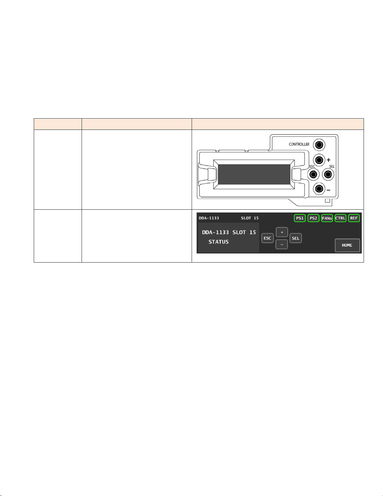
There are two types of local control panel:
Panel type Frame models Appearance
Physical Densité-2
Densité-3
Densité-3+FR1
Touch screen Densité 3+FR4
GV Node
The local control panel is fastened to the front of the controller card.
•The physical panel is accessed by opening the front door of the frame.
•The touch screen panel is accessed through an aperture in the frame door.
The panel consists of a display capable of displaying two lines of text, each 16 characters in length, and four
pushbuttons. The functionality of the pushbuttons is as follows:
[+] [–] Used for menu navigation and value modification
[SEL] Gives access to the next menu level. When a parameter value is shown, pushing this button once
enables modification of the value using the [+] and [–] buttons; a second push confirms the new value
[ESC] Cancels the effect of parameter value changes that have not been confirmed; pushing [ESC] causes the
parameter to revert to its former value.
Pushing [ESC] moves the user back up to the previous menu level. At the main menu, [ESC] does not
exit the menu system. To exit, re-push the [SEL] button for the card being controlled.
If no controls are operated for 30 seconds, the controller reverts to its normal standby status, and the selected card’s
STATUS reverts to its normal operating mode.
To assign the local control panel to the DDA-1133:
•Physical Panel: Push the SELECT button on the DDA-1133 card edge (see Section 1.4).

GUIDE TO INSTALLATION AND OPERATION
6| DDA-1133
•Touch-screen panel: In the home screen, touch the virtual button corresponding to this DDA-1133.
The STATUS LED on the DDA-1133 flashes yellow, and the touch-screen status shows yellow for the DDA-1133.
Use the control panel buttons to navigate through the menu, as described above. The complete menu structure is
shown below.
3.2.1 Menu for local control
Using the menu, the user can:
oDisplay the error status if any is present
oAdjust the No Signal Delay and Signal Threshold to set the conditions of a No Signal alarm. A signal absence
is declared when the level is lower than the threshold during the selected delay.
oAdjust the correction applied to the input signal:
AUTO A START will initiate an automatic sequence, indicated by PROCESS. When the input status
becomes correct it will stop and SUCCESS will be displayed. FAIL will be displayed to indicate that
no correction has been found that will yield to a correct input status.
LENGTH This command allows a manual adjustment of the correction applied to the input signal. The input
status is displayed at the same time to ease the setting.
oEnable or disable the internal Reclocker..
oConfigure the different alarms, setting the alarm level (color displayed on the front panel status LED, and
severity reported to the frame controller) and selecting whether the alarm is to be reported on the frame’s GPI
interface.
oAccess the firmware version of the card programmable devices.

GUIDE TO INSTALLATION AND OPERATION
DDA-1133 | 7

GUIDE TO INSTALLATION AND OPERATION
8| DDA-1133
3.3 iControl Interface
The operation of the DDA-1133 may be controlled using Grass Valley’s iControl
system.
This section describes the control panels associated with the DDA-1133 and their
uses.
Please consult the iControl User’s Guide for information about setting up and
operating iControl.
In iControl Navigator or iControl Websites, double-click on the DDA-1133 icon to
open the control panel.
Status Icons
At the top, to the left of the Grass Valley logo, are two status icons that report
various aspects of the card’s operation.
The leftmost (CTRL) icon shows whether card configuration is manual [LOC] or via
iControl [REM]. The second icon reports the input status.
Move the cursor over an icon to see its current status in the message area below
the icons. If there is an error status, the message will appear automatically. If there
are multiple error messages, the display will cycle through them.
Load Factory
The Factory profile is a read-only set of factory-selected values that can be used to
return your DDA-1133 to a standard operating condition.
•The default values are shown as underlined in the DDA-1133 Menu on page 7.
3.3.1 Status Tab
This tab displays the status of the various errors that could be associated with the input signal.
The PCM Status box will display either PCM, non-audio, Dolby-E or AC-3 according to the type of audio signal.
3.3.2 Config Tab
No Signal Delay
This tab sets the card’s behavior in the event of a loss or absence of audio signal
content.
A signal absence is declared when the signal level is lower than the signal threshold
during the selected period.
The threshold can be set through the pull-down box to –72, -66, -60, -54 or -48
dBFS, the default value is –60 dBFS.
The signal absence period can be adjusted from 0 to 255 seconds. The default value
is set to 15 s. An input box is available to enter a numerical value directly.
Cable Correction
Mode MANUAL
This mode allows a manual adjustment of the correction applied to the input signal.
Look at the input status icon to facilitate the setting. An input box is available to enter
a numerical value directly.
Figure
3-1 Status Tab
Figure
3-2 Config Tab

GUIDE TO INSTALLATION AND OPERATION
DDA-1133 | 9
Mode AUTO
A START will initiate an automatic sequence, indicated by PROCESS. When the input status becomes correct it will
stop and SUCCESS will be displayed. FAIL will be displayed to indicate that no correction has been found that will
yield a correct input status
3.3.3 Alarms Tab
Selecting the Alarm config button opens a separate window for error status reporting. The Alarm Configuration Panel
shows a listing of the alarms reported by the card.
The Card LED, Overall alarm and GSM contribution columns contain pull-down lists that allow the level of contribution
of each individual alarm to the alarm named in the column heading to be set.
Card LED
This column allows configuration of the contribution of selected individual alarms to the status LED located on the
front card edge. The Card LED status is shown at the bottom of the alarm tree in the Status/Name column.
Overall Alarm
This column allows configuration of the contribution of each individual alarm to the Overall Alarm associated with this
card. The Overall Status is reflected by the color of the indicator attached to the card in iControl Navigator. It is also
displayed in the upper left corner of the iControl Interface of the DDA-1133.
GSM Contribution
This column allows configuration of the contribution of each individual alarm to the GSM Alarm Status associated with
this card. GSM is a dynamic register of all iControl system alarms, and is also an alarm provider for external
applications. The possible values for this contribution are related to the Overall alarm contribution:
• If the Overall alarm contribution is set to Disabled, the GSM alarm contribution can be set to any available value
• If the Overall alarm contribution is selected as any level other than disabled, the GSM contribution is forced to
follow the Overall Alarm.
Figure
3-3 Alarms Tab and Alarms Configuration panel

GUIDE TO INSTALLATION AND OPERATION
10 | DDA-1133
Levels associated with these alarms: the pull-down lists may contain some or all of the following options:
The alarm makes no contribution (black icon)
The alarm is of minor importance (yellow icon)
The alarm is of major importance (orange icon)
The alarm is of critical importance (red icon)
The alarm exists but has no effect (used for text and composite alarms)
Shortcut: if you click in one of the Set all command under each major heading in the Status/Name line, you will
open a pull-down that lets you assign a level to all alarms in that column simultaneously.
Log Events
iControl maintains a log of alarm events associated with the card. The log is useful for troubleshooting and identifying
event sequences. Click in the checkbox to enable logging of alarm events for each individual alarm.
At the bottom of the window are several other controls:
Overall alarm and GSM contribution follow card LED
Click in the checkbox to force the Overall alarm and GSM
contribution to be identical to the Card LED status
•All Overall alarms for which there is a Card LED alarm
will be forced to match the Card LED alarm
•All Overall Alarms for which there is no Card LED alarm
will be forced to Disabled
A warning box will open allowing you to confirm the action,
since it will result in changes to the configuration and there is
no undo function.
.
Copy to other cards
Click this button to open a panel that allows the alarm
configuration set for this card to be copied into another
DDA-1133 card.
Select one or more destination cards from the list in the
window by clicking in check boxes, or all of them by
clicking in the All checkbox.
Figure
3-5 Copy to Other Cards
Figure
3-4 Overall Follow Card LED - Warning Box

GUIDE TO INSTALLATION AND OPERATION
DDA-1133 | 11
Get alarm keys
Click this button to open a save dialog where you can
save a file containing a list of all alarms on this card and
their current values, along with an Alarm Key for each.
The alarm keys are useful for system integration and
troubleshooting.
The file is saved in .csv format
3.3.4 Info Tab
The Info panel displays information about the DDA-1133.
The boxes titled Label, Short Label, Source ID and Comments are editable; you can
enter your own information.
The Advanced button displays LongID of this card, which is its address in the
iControl system.
The Details button displays the card firmware version.
The Remote System Administration button at the bottom of the window opens the
Joining Locators data window, which lists remote lookup services to which this DDA-
1133 is registered. The ADD button in that window allows new lookup services to be
added.
Figure
3-7 Info Tab
Figure
3-6 Get Alarm Keys

GUIDE TO INSTALLATION AND OPERATION
12 | DDA-1133
4 Specifications
Input
Signal AES3 (ANSI S4.40)
Level 0.1 to 7.0 Vpp
Impedance 110 Ωbalanced
Equalization up to 1000 m (DRAKA ref. KFB Audio PBG110)
Outputs
Signal AES3 (ANSI S4.40)
Level 4 Vpp
Impedance 110 Ωbalanced
Rise/fall time 25 ns
Over/under shoot 5.5%
Jitter reduction 6 dB (@ 20 kHz)
Specific jitter <0.005 UI pp (700 Hz to 100 kHz)
Signal Processing
Sampling: 28 to 100 kHz
Processing delay:
- Reclocker ON <60.7 µs @ 48kHz (< 3 samples)
- Reclocker OFF 75 ns typ.
Signal absence threshold -48 / -72 dBFS (6 dB steps)
Signal absence delay from 0 to 255 s
V, U, C, P bits transparency
Miscellaneous
Power with 4 outputs: 1.5 W
with 7 outputs: 2.0 W
with 9 outputs: 2.0 W

GUIDE TO INSTALLATION AND OPERATION
DDA-1133 | 13
5 Contact Us
Grass Valley Technical Support
For technical assistance, contact our international support center, at
1-800-547-8949 (US and Canada) or +1 530 478 4148.
To obtain a local phone number for the support center nearest you, please consult the Contact Us section of Grass
Valley’s website (www.grassvalley.com).
An online form for e-mail contact is also available from the website.
Corporate Head Office
Grass Valley
3499 Douglas-B.-Floreani
St-Laurent, Quebec H4S 2C6
Canada
Telephone: +1 514 333 1772
Fax: +1 514 333 9828
www.grassvalley.com
Table of contents
Other Belden Amplifier manuals

Belden
Belden GRASS VALLEY HDA-3911 Instruction Manual

Belden
Belden Grass Valley HDA-1911 Instruction Manual

Belden
Belden grass valley IQSDA41 Series User manual

Belden
Belden Grass Valley VEA-1023 Instruction Manual

Belden
Belden PPC Entry Series User manual

Belden
Belden GRASS VALLEY HDA-1941 Instruction Manual

Belden
Belden GRASS VALLEY HDA-3961 Instruction Manual
Popular Amplifier manuals by other brands

Kollmorgen
Kollmorgen S700 Series instruction manual

Blackstar Amplification
Blackstar Amplification AMPED 1 Setup guide

Powerwave Technologies
Powerwave Technologies NTUM30DA Installation & service manual

Pearller
Pearller HY880MBT instruction manual

Key Digital
Key Digital KD-AMP220 operating instructions

Rotel
Rotel RB-870BX owner's manual