Belden GRASS VALLEY DENSITE Series Instruction Manual

DENSITÉ series
LNS-3901
3Gbps/HD/SD Line Synchronizer
Guide to Installation and Operation
M932-9400-112
24 December 2014
3499 Douglas-B.-Floreani
St-Laurent, Québec, Canada H4S 2C6
Tel. 514-333-1772
Fax. 514-333-9828
www.grassvalley.com
© 2014Grass Valley A Belden Brand

GUIDE TO INSTALLATION AND OPERATION
LNS-3901
Electromagnetic Compatibility
This equipment has been tested for verification of compliance with FCC Part 15, Subpart B requirements for
Class A digital devices.
NOTE: This equipment has been tested and found to comply with the limits for a Class A digital device, pursuant to
part 15 of the FCC Rules. These limits are designed to provide reasonable protection against harmful interference
when the equipment is operated in a commercial environment. This equipment generates, uses, and can radiate
radio frequency energy and, if not installed and used in accordance with the instruction manual, may cause harmful
interference to radio communications. Operation of this equipment in a residential area is likely to cause harmful
interference in which case the user will be required to correct the interference at his own expense.
This equipment has been tested and found to comply with the requirements of the EMC directive
2004/108/CE:
•EN 55022 Class A radiated and conducted emissions
•EN 55024 Immunity of Information Technology Equipment
•EN 61000-3-2 Harmonic current injection
•EN 61000-3-3 Limitation of voltage changes, voltage fluctuations and flicker
•EN 61000-4-2 Electrostatic discharge immunity
•EN 61000-4-3 Radiated electromagnetic field immunity – radio frequencies
•EN 61000-4-4 Electrical fast transient immunity
•EN 61000-4-5 Surge immunity
•EN 61000-4-11 Voltage dips, short interruptions and voltage variations immunity

GUIDE TO INSTALLATION AND OPERATION
LNS-3901
Table of Contents
1LNS-3901 3Gbps/HD/SD Line Synchronizer...........................................................................1
1.1 Introduction ......................................................................................................................................... 1
1.2 Features.............................................................................................................................................. 1
1.3 Functional Block Diagram................................................................................................................... 1
1.4 Front Card-edge Interface................................................................................................................... 2
2Installation................................................................................................................................3
2.1 Unpacking........................................................................................................................................... 3
2.2 Installation in the Densité frame.......................................................................................................... 3
2.3 Rear Panels and Connectors.............................................................................................................. 3
3User Interface...........................................................................................................................5
3.1 Control options.................................................................................................................................... 5
3.2 Card-Edge Status LED ....................................................................................................................... 5
4Local control using the Densité frame control panel ............................................................6
4.1 Overview............................................................................................................................................. 6
4.2 Menu for local control.......................................................................................................................... 6
5Remote control using iControl................................................................................................7
5.1 The iControl graphic interface window................................................................................................ 7
5.2 Video Input / Output panel .................................................................................................................. 9
5.2.1 Line synchronizer operation................................................................................................. 10
5.2.2 Operational Setup................................................................................................................ 10
5.3 Reference panel................................................................................................................................ 12
5.4 Factory / Presets panel..................................................................................................................... 13
5.5 Alarm Config panel ........................................................................................................................... 13
5.6 Info panel .......................................................................................................................................... 16
6Specifications.........................................................................................................................18
7Grass Valley Technical Support............................................................................................19
ANNEX 1 – LNS-3901 Local User Interface ................................................................................20
ANNEX 2 – Updating the LNS-3901 ............................................................................................21

GUIDE TO INSTALLATION AND OPERATION
LNS-3901

GUIDE TO INSTALLATION AND OPERATION
LNS-3901 | 1
1 LNS-3901 3Gbps/HD/SD Line Synchronizer
1.1 Introduction
The LNS-3901 is a 3G/HD/SD line synchronizer capable of handling hot switches between sources of the same
format and phased by less than 10 lines compared to the reference. The output timing will be programmed from ½ to
10 ½ lines after the 0H of the reference. The reference signal is an analog black burst reference, tri-level sync, or the
internal URS frame reference signal.
The LNS-3901 is a very high density card. Up to 20 cards can fit in a Densité 3 frame. It is also a low cost solution to
synchronize video signals at the output of a router and prevent downstream video glitches. Using the appropriate rear
module, a bypass relay is available to automatically bypass the card’s processing when the card loses power or if it is
removed from the frame.
All card parameters and statuses can be controlled or monitored through iControl.
1.2 Features
•3Gbps/HD/SD input
•Supports 3Gbps level A and level B (dual link)
•Automatic detection of video input format.
•Flexible external reference or internal URS frame reference input
•Clean output on video input “hot switches” within a 10-line window.
•Output timing can be adjusted from ½ to 10 ½ lines after reference.
•Automatic pass-through of all ancillary data, VBI and embedded audio.
•Removes high and low frequency jitter out of the video signal
•Bypass relay on the –R rear module
1.3 Functional Block Diagram
Figure 1.1 LNS-3901 Functional Block Diagram

GUIDE TO INSTALLATION AND OPERATION
LNS-3901 | 3
2 Installation
2.1 Unpacking
Make sure the following items have been shipped with your LNS-3901. If any of the following items are missing,
contact your distributor or Miranda Technologies Inc.
•LNS-3901 3G/HD/SD Line Synchronizer
•A rear panel. (see Section 2.3 below for details)
2.2 Installation in the Densité frame
The LNS-3901 and its associated rear connector rear panel must be mounted in a DENSITÉ 3 RU frame. It is not
necessary to switch off the frame’s power when installing or removing the card. See the DENSITÉ Frame manual for
detailed instructions for installing cards and their associated rear panels.
2.3 Rear Panels and Connectors
Two different rear panels are available for the LNS-3901:
LNS-3901-3SRP Rear panel
LNS-3901-3SRP-R Rear panel with integral bypass relay
These rear panels are shown in the figure below, and their various inputs and outputs are described.
LNS-3901-3SRP
LNS-3901-3SRP-R
REF IN – Studio reference input
For external synchronization, connect a black studio reference signal to the BNC labeled REF IN.
The reference input must conform to SMPTE 170M/SMPTE 318M/ITU 624-4/BUT 470-6 for standard definition
signals and SMPTE 274M / SMPTE 296M for high definition signals and is used to phase the HD/SD SDI outputs to

GUIDE TO INSTALLATION AND OPERATION
4| LNS-3901
the studio. A reference mismatch error will occur if there is a difference between the input video format’s frame rate
and the reference format’s frame rate. When a reference mismatch occurs, the LNS-3901 output will be undefined
and unstable. The error will be reported by the card-edge status LED (see section 3.2) and by the Input Status Icon in
the iControl panel (see section 5.1).
Note that in the case of HD signals of the same frame rate, any reference signal may be used to genlock any output
signal, regardless of scan type (progressive or interlaced). When a 720p/tri-level sync reference signal is used with an
interlaced output, the output is synchronized but there may be a delay of one field depending on when the
synchronization started.
In the case of HD 1080p23 and 1080p23SF input signals, it is recommended to use a REF-1801 card connected to a
black burst analog reference that has SMPTE 318M signaling. The card must be configured to use the intra frame
URS signal. This is the only way to ensure proper output alignment and clean switch.
3G/HD/SD IN – Serial digital 3G/HD/SD input
Connect a serial digital video signal, conforming to the SMPTE 425M standard for 3G input signals, SMPTE 292M
standard for HD input signals or SMPTE 259M standard for SD input signals, to the BNC labeled 3G/HD/SD IN. The
LNS-3901 will automatically switch to the detected line/frame rate format.
•NOTE - The input signal must be locked to the reference in use (either the external reference or the URS)
3G/HD/SD OUT – Serial digital video outputs
The LNS-3901 provides two 3G/HD/SD SDI video outputs on BNC connectors, labeled 3G/HD/SD OUT 1 and 2. The
SDI video signal conforms to the SMPTE 425M, SMPTE 292M or SMPTE 259M-C standard. The same signal is
carried on all outputs.
•NOTE – When the bypass relay on the LNS-3901-3SRP-R rear panel is activated, output 2 is connected directly
to the 3G.HD/SD IN input connector, bypassing the card.

GUIDE TO INSTALLATION AND OPERATION
LNS-3901 | 5
3 User Interface
3.1 Control options
The LNS-3901 can be controlled in two different ways:
•The local control panel and its push-buttons can be used to move through a menu of parameters and to adjust
parameter values (see section 4).
•Miranda’s iControl system can be used to access the card’s operating parameters from a remote computer, using
a convenient graphical user interface (GUI) (see section 5).
3.2 Card-Edge Status LED
The status monitor LED is located on the front card-edge of the LNS-3901, and is visible through the front access door
of the DENSITÉ frame. This multi-color LED indicates the status of the LNS-3901 by color, and by flashing/steady
illumination.
The chart shows how the various error conditions that can be flagged on the LNS-3901 affect the LED status.
•If a cell is gray, the error condition cannot cause the LED to assume that status.
•If more than one LED status is possible for a particular error condition, the status is configurable.
See Section 5.16 for details.
•The factory default status is shown by a
The LED will always show the most severe
detected error status that it is configured to
display, and in the chart error severity
increases from left to right, with green
representing no error/disabled, and flashing
red the most severe error.
If the LED is Flashing Yellow, it means that
the card is selected for local control using
the Densité frame’s control panel. See
Section 4 for details.
Error Condition
LED Status
Green
Yellow
Red
Flashing
Red
Cooling Fan 1 error
FPGA error
Dataflash Error
No Rear
Reference missing
Reference mismatch
Carrier 1 detect error
Input timing outside range

GUIDE TO INSTALLATION AND OPERATION
6| LNS-3901
4 Local control using the Densité frame control panel
4.1 Overview
Push the SELECT button on the LNS-3901 card edge (see Section 1.4) to assign the local control panel to operate
the LNS-3901. Use the control panel buttons to navigate through the menu, as described below.
All of the cards installed in a Densité frame are
connected to the frame’s controller card, which
handles all interaction between the cards and the
outside world. There are no operating controls located
on the cards themselves. The controller supports
remote operation via its Ethernet ports, and local
operation using its integrated control panel.
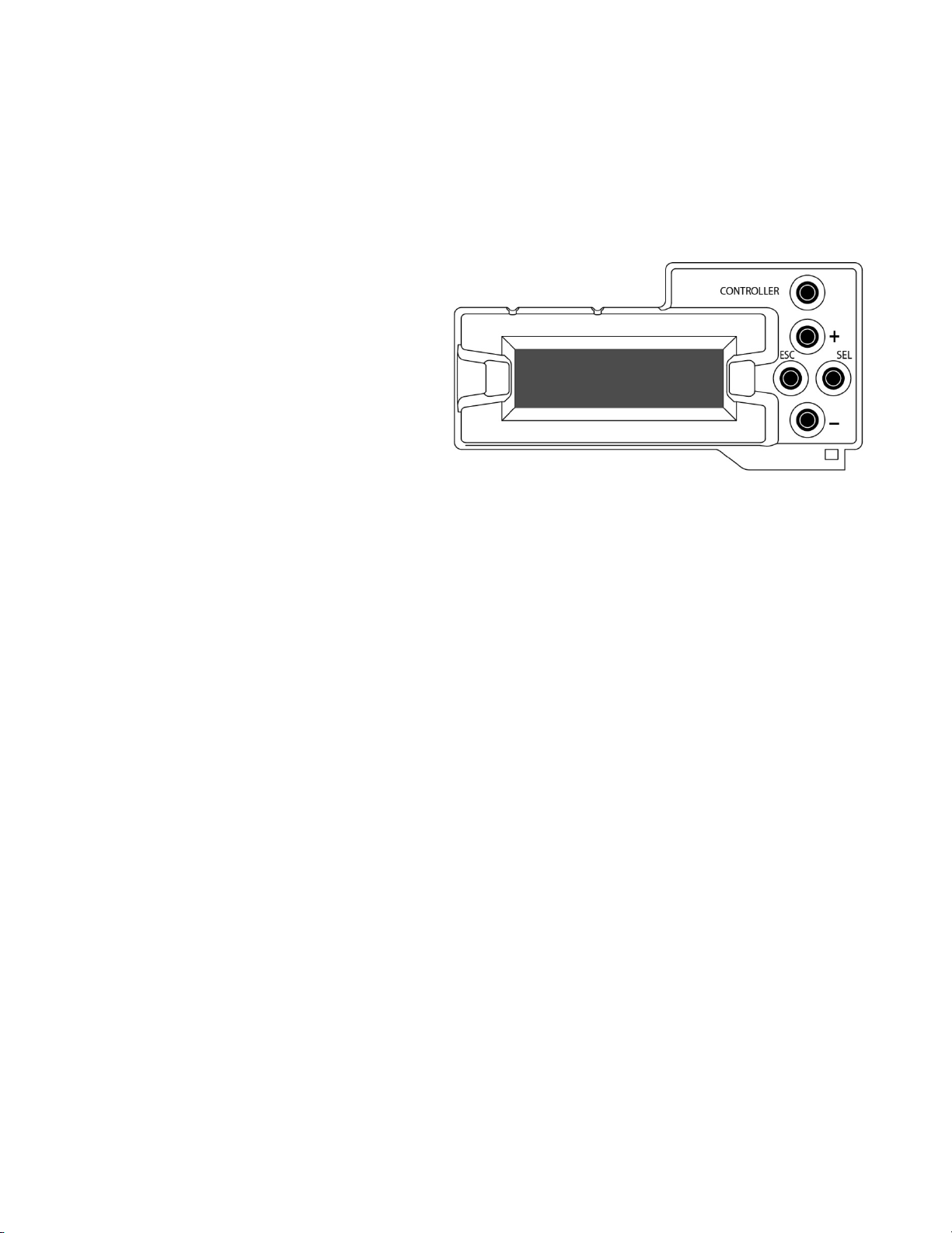
The local control panel is fastened to the front of the
CPU-ETH2 controller card, and when installed can be
accessed by opening the front door of the frame. The
panel consists of a display unit capable of displaying
two lines of text, each 16 characters in length, and five
pushbuttons.
The panel is assigned to operate any card in the frame by pushing the SELECT button on the front edge of that card.
•Pushing the CONTROLLER button on the control panel selects the Controller card itself.
•The STATUS LED on the selected card flashes yellow.
The local control panel displays a menu that can be navigated using the four pushbuttons located beside the display.
The functionality of the pushbuttons is as follows:
[+] [–] Used for menu navigation and value modification
[SELECT] Gives access to the next menu level. When a parameter value is shown, pushing this button once
enables modification of the value using the [+] and [–] buttons; a second push confirms the new value
[ESC] Cancels the effect of parameter value changes that have not been confirmed; pushing [ESC] causes the
parameter to revert to its former value.
Pushing [ESC] moves the user back up to the previous menu level. At the main menu, [ESC] does not
exit the menu system. To exit, re-push the [SELECT] button for the card being controlled.
If no controls are operated for 30 seconds, the controller reverts to its normal standby status, and the selected card’s
STATUS LED reverts to its normal operating mode.
4.2 Menu for local control
The LNS-3901 has operating parameters which may be adjusted locally at the controller card interface.
•Press the SELECT button on the LNS-3901 front card edge to assign the Densité frame’s local control panel
to the LNS-3901
•Use the keys on the local control panel to step through the displayed menu to configure and adjust the LNS-
3901.
The complete menu structure is shown in Annex 1 to this document, beginning on page 20.
Figure
4-1 Densité Frame local control panel

GUIDE TO INSTALLATION AND OPERATION
LNS-3901 | 7
5 Remote control using iControl
The operation of the LNS-3901 may be controlled using Miranda’s iControl system.
•This manual describes the control panels associated with the LNS-3901 and their use.
•Please consult the iControl User’s Guide for information about setting up and operating iControl.
In iControl Navigator or iControl Websites, double-click on the LNS-3901 icon to open the control panel.
5.1 The iControl graphic interface window
The basic window structure for the LNS-3901 is shown in figure 5.1. The window identification line gives the card type
(LNS-3901) and the slot number where the card is installed in its Densité frame.
There are three main sections in the window itself, identified in figure 5.1:
Section 1. The top section displays five icons on the left. These icons report different statuses such as card
communication status, input signal and reference signal format and statuses. In some instances, they relate to
conditions defined through parameters settings.
Icon # 1 2 3 4 5
Move the mouse over an icon and a status message appears below the icon providing additional information.
If there is an error, the error status message appears in the message area without mouse-over.
•If there are multiple errors, the error messages cycle so all can be seen
•The icon whose status or error message is shown is highlighted with a mauve background
1
2
3
Figure
5-1 LNS-3901 iControl graphic interface window
3

GUIDE TO INSTALLATION AND OPERATION
8| LNS-3901
The table below describes the various status icons that can appear, and how they are to be interpreted.
•In cases where there is more than one possible interpretation, read the error message in the iControl window to
see which applies.
Icon #1 – Manual Card Configuration
(green)
Remote card control activated. The iControl interface can be used to operate the
card
(yellow)
Local card control active, The card is being controlled using the Densité frame
control panel, as described in section 4. Any changes made using the iControl
interface will have no effect on the card.
Icon #2 – Input status
(green)
Signal detected and valid.
•Beneath the icon, the format will be indicated as 3G, HD or SD, and the
specific format details will be listed if the cursor is moved over the icon.
(red)
Signal absent
No rear
Reference mismatch
Video/TRS error
Icon #3 – Reference
(green)
Reference OK. Mouse over to see the source of the reference, and its format, e.g.
External, NTSC
(red)
Reference missing. The reference is required for correct line synchronizer operation.
(gray)
Reference absent
Icon #4 – Hardware Health
(green)
Hardware OK
(red)
Hardware Health Monitoring (Fan1, Fan2, Hardware fault detected)
If this icon appears red, return the card to Miranda and specify the error code.

GUIDE TO INSTALLATION AND OPERATION
LNS-3901 | 9
Icon #5 – Input Window
(green)
Input timing within range
(red)
Input timing outside range
Section 2. The left portion of the window contains all the parameter groups, which become highlighted when they are
selected; the main panel (3) then displays the group’s set of parameters. Each of the groups is described in detail
below.
Section 3. The main panel contains all the parameters specific to the group selected. It may contain several tabs to
help manage the different parameters.
Each of the panels associated with the groups accessed from the buttons in Section 2, and shown in Section 3, is
described individually in the following sections.
5.2 Video Input / Output panel
This panel monitors the status of the input timing compared to
the reference, and sets up the synchronizer timing.
Bypass Relay: select the checkbox to activate the bypass
relay in the LNS-3901-3SRP-R rear panel
•This connects the rear panel input directly to the output,
bypassing the card.
•The checkbox will not appear if a rear panel with no
bypass relay is installed.
Input timing to reference: the databox shows the measured
horizontal timing of the current input signal compared to the
selected timing reference for the LNS-3901.
Input window range: the databox shows the positioning of the
10-line window with respect to the selected reference for the
LNS-3901. This is adjusted using the Input Window slider
below.
Timing
The Total Delay shows the current output timing with respect
to the timing reference selected for the LNS-3901 card. This
is the sum of the timing adjustments selected using the two
sliders.
Vertical (lines):sets the offset of the 10-line input window with respect to the reference over the range 1 to 10 lines.
Horizontal (
µ
sec): sets the fine timing at the LNS-3901 output.
See the following description for an explanation of the functionality of these adjustments.
Figure
5-2 Video Input / Output panel

GUIDE TO INSTALLATION AND OPERATION
10 | LNS-3901
5.2.1 Line synchronizer operation
The Line synchronizer in the LNS-3901 can conceal a hot-switch occurring in the input signal without producing
artifacts on the output, under specific conditions.
•In order to enable the line synchronizer, a valid external reference signal must be installed or the URS signal
must be selected as the reference in the Reference panel (see section 5.3).
•If the reference is missing when the line synchronizer is activated, the Input timing to reference box will indicate
“Missing reference” in red, and the reference status icon at the top of the iControl window will turn red and show
the message “Reference missing”.
For the line synchronizer to function correctly, the following requirements must be met:
•All input signals must be synchronized to the reference.
•The signals on both sides of a hot switch must fall within a ten-line window that also contains the reference.
If the two signals are more than 10 lines apart, the output will be glitchless, but the output image content will
be shifted up or down by 10-plus lines.
When a reference is present, the LNS-3901 reports the difference in timing between the input and the reference in the
Input timing to reference window, expressed in lines plus microseconds.
•If the signal is inside the 10-line input window, the timing will be shown in black
•If the signal is outside the 10-line input window, the timing will be shown in red
In order to provide maximum flexibility in configuring the LNS-3901, the position of the input window with respect to
the reference is user-adjustable. The effect is to adjust the overall delay between the input reference and the output,
in one line increments. This is accomplished using the Vertical (lines) slider, over a range of 1 to 10 lines. The actual
position of the window is offset from the reference by ½ H, and is shown in the Input Window Range databox.
A further +/- ½ line fine adjustment of the output timing is provided by the Horizontal (
µ
sec) slider
5.2.2 Operational Setup
In operation, the objective is to set up the line synchronizer timing so that all possible inputs that might undergo a hot
switch fall within the input window, while keeping the overall delay as low as possible.
Select each input signal in sequence, and adjust the Vertical slider to the lowest value that shows all of their timing
values in the Timing databox above in black.
Note that signals falling into the very upper edge of the 10-line window cannot be compensated directly if they fall
within the processing delay of the LNS-3901, so another full line of delay must be added.
The diagram on the next page (Figure 5.3) illustrates the various possible set-ups of the LNS-3901, based on the
Vertical slider setting:

GUIDE TO INSTALLATION AND OPERATION
LNS-3901 | 11
Figure 5-3 LNS-3901 timing

GUIDE TO INSTALLATION AND OPERATION
12 | LNS-3901
5.3 Reference panel
This panel allows the selection of the reference to be used
by the LNS-3901.Icons in the Reference Presence area
indicate which references are available to this LNS-3901.
Use the radio buttons in the Reference Source area to select
from the following options:
•Auto – this mode selects the first source detected in this
order of priority:
oExternal reference from the rear panel REF IN
oURS
oSelected Input signal
•URS (Universal Reference Signal) – selects the internal
reference from the backplane
•Input – uses the currently-selected input signal. Note
that, in this case, the LNS-3901 cannot provide
glitch-free hot switch correction, because the
reference timing changes with the input.
URS Format – use the radio buttons in the URS Format area
to select whether the URS is OFF, 29.97 Hz or 25 Hz.
•When URS is OFF, the URS reference format source
cannot be selected, and will also be ignored by the
automatic detection mode.
Note: Make sure the input signal is, at all times, locked to
the selected reference signal.
The table shows which reference formats are suitable for all possible input video formats.
Figure
5-4 Reference panel

GUIDE TO INSTALLATION AND OPERATION
LNS-3901 | 13
5.4 Factory / Presets panel
Load Factory: Clicking this button will restore the card to a
factory default state. Two checkboxes enable the user to
choose whether to include Parameters and/or Alarms in the
restoration process
5.5 Alarm Config panel
This panel allows the alarm reporting of the LNS-3901 to be configured. The panel opens in a new window when the
button is clicked, and can be resized if needed.
Figure
5-6 Alarm Configuration panel
Figure
5-5 Factory / Presets panel

GUIDE TO INSTALLATION AND OPERATION
14 | LNS-3901
The panel is organized in columns.
Status/Name
This contains an expandable tree listing all the alarms reported by this LNS-3901 card.
•Each alarm name includes an icon that shows its current status
•Some alarms may be text-only and the alarm status is shown in the name and not by a status icon
The Card LED, Overall alarm and GSM contribution columns contain pulldown lists that allow the level of
contribution of each individual alarm to the alarm named in the column heading to be set.
•If there is no arrowhead in the box, there is no pulldown and the alarm is not user-configurable
Card LED
This column allows configuration of the contribution of selected individual alarms to the status LED located on the
front card edge. The Card LED status is shown at the bottom of the alarm tree in the Status/Name column.
Overall Alarm
This column allows configuration of the contribution of each individual alarm to the Overall Alarm associated with this
card. The Overall Alarm is shown in the upper left corner of the iControl panel, and also appears at the bottom of the
Status/Name column.
GSM Contribution
This column allows configuration of the contribution of each individual alarm to the GSM Alarm Status associated with
this card. GSM is a dynamic register of all iControl system alarms, and is also an alarm provider for external
applications. The possible values for this contribution are related to the Overall alarm contribution:
•If the Overall alarm contribution is selected as Disabled, the GSM alarm contribution can be set to any available
value
•If the Overall alarm contribution is selected as any level other than disabled, the GSM contribution is forced to
follow the Overall Alarm.
Levels associated with these alarms:
The pulldown lists may contain some or all of the following options:
The alarm makes no contribution (black icon)
The alarm is of minor importance (yellow icon)
The alarm is of major importance (orange icon)
The alarm is of critical importance (red icon)
The alarm exists but has no effect (used for text and composite alarms)
Shortcut: if you click on “Set All” in one of the columns beside a major heading in the Status/Name column, you
will open a pulldown list that lets you assign a level to all alarms in that section of the column simultaneously.
Once the alarms are configured, you may accept the changes or discard them:
Log Events
iControl maintains a log of alarm events associated with the card. The log is useful for troubleshooting and identifying
event sequences. Click in the checkbox to enable logging of alarm events for each individual alarm.
At the bottom of the window are several other controls

GUIDE TO INSTALLATION AND OPERATION
LNS-3901 | 15
Overall alarm and GSM contribution follow card LED
Click in the checkbox to force the Overall alarm and GSM contribution to be identical to the Card LED status
•All Overall alarms and GSM contributions for which there is a Card LED alarm will be forced to match the Card
LED alarm
•All Overall Alarms and GSM contributions for which there is no Card LED alarm will be forced to Disabled
A warning box will open allowing you to confirm the
action, since it will result in changes to the configuration
and there is no undo function.
Copy to other cards
Click this button to open a panel that allows the alarm
configuration set for this card to be copied into another LNS-
3901 card.
•Select one or more destination cards from the list in the
window by clicking in the checkboxes, or all of them by
clicking in the All checkbox
Get alarm keys
Click this button to open a save dialog where you can save a
file containing a list of all alarms on this card and their current
values, along with an Alarm Key for each. The alarm keys are
useful for system integration and troubleshooting.
•The file is saved in .csv format
Figure
5-7 Warning for Follow LED change
Figure
5-9 Get Alarm Keys dialog
Figure
5-8 Copy to Other Cards window

GUIDE TO INSTALLATION AND OPERATION
16 | LNS-3901
OK, Apply, Cancel
•OK accepts the settings and closes the window once the card confirms that there are no errors.
•Apply accepts the settings, but leaves the window open
•Cancel closes the window without applying any changes, and leaves the previous settings intact.
5.6 Info panel
The top two lines in this panel identify the model of this LNS-
3901, and the rear panel that is currently installed.
When the LNS-3901 is included in an iControl environment,
certain information about the card should be available to the
iControl system. The user can enter labels and comments
that will make this card easy to identify in a complex setup.
This information is entered into data boxes in the Info control
panel.
Rear Type: specifies the rear module currently
installed.
Label: type the label that is shown for this LNS-
3901 when it appears in iControl
applications
Short Label type the short-form label that iControl
uses in some cases (8 characters)
Source ID type a descriptive name for this LNS-
3901
Comments: type any desired text
The remaining data boxes show manufacturing information
about this card.
Three buttons in the panel give access to other information.
•Details…: Reports the Firmware version, service version, and panel
version for this card
Fi
gure 5-11 Details window
Figure
5-10 Info panel
This manual suits for next models
1
Table of contents
Other Belden Recording Equipment manuals
Popular Recording Equipment manuals by other brands

Zodiac
Zodiac ePump Installation and operation manual

Jobsite
Jobsite S-4 Installation and user guide

Mutable Instruments
Mutable Instruments Rings quick start guide

swissonic
swissonic USB Studio D Mk. II operating manual

Waves
Waves ELEMENT 2.0 user guide

Zennio
Zennio DALIBOX ZDI-DLB6 Technical documentation