belfab NBM-OP Instructions for use

Instruction And Maintenance Manual
For Dust Collector
Manuel D’Instructions Et De Maintenance
Pour Dépoussiéreur
Model /: NBM-OP
Modèle
erial Number /:
Numéro De érie


TABLE OF CONTENT / TABLE DE MATIÈRE
CAUTION ....................................................................................... 1
WARNING ...................................................................................... 2
DESCRIPTION ................................................................................. 3
INSTALLATION ............................................................................... 4
INITIAL START-UP .......................................................................... 7
OPERATING INSTRUCTIONS ............................................................. 8
MAINTENANCE ............................................................................... 9
TROUBLESHOOTING GUIDE ........................................................... 11
WARRANTY .................................................................................. 12
RECOMMENDED SPARE PARTS LIST .................................. APPENDIX 1
DRAWINGS .................................................................... APPENDIX 2
(OPTION PNEUMATIC DUST TRANSFER SYSTEM ................ APPENDIX 3
AVERTISSEMENT .......................................................................... 13
MISE EN GARDE ........................................................................... 14
DESCRIPTION ............................................................................... 15
INSTALLATION ............................................................................. 16
MISE EN MARCHE INITIALE ............................................................ 19
INSTRUCTIONS D'OPÉRATION ........................................................ 20
ENTRETIEN GÉNÉRAL .................................................................... 23
PROBLÈMES OCCASIONNELS ......................................................... 24
GARANTIE .................................................................................... 25
LISTE DE PIÈCES DE RECHANGE RECOMMENDÉES ................ ANNEXE 1
DESSINS .......................................................................... ANNEXE 2
(OPTION SYSTÈME DE TRANSFERT PNEUMTIQUE ................. ANNEXE 3

1
CAUTION
Make sure your installation complies with the local authorities and with the
appropriate NFPA Standards, which are available from the National Fire
Prevention Association.
These NFPA standards include, but are not limited to:
- Standard for the Prevention of Fires and Dust Explosions in Agricultural and Food
Processing Facilities, NFPA 61
- Standard for Combustible Metals, Metal Powders and Metal Dusts, NFPA 484
- Standard for the Prevention of Fires and Explosions in Wood Processing and
Woodworking Facilities, NFPA 664
-
Standard for the Prevention of Fire and Dust Explosions from the Manufacturing,
Processing and Handling of Combustible Particulate Solids, NFPA 654
Notes for the province of Quebec
These regulations include the RSST (Règlement sur la santé et la sécurité du
travail). Below is an excerpt from article 59.1 regarding open dust collectors
installed inside in the woodworking industry. Please review the RSST for the
complete information (www.csst.qc.ca .
-Open dust collectors are located at least 20 ft away from any means of egress or
area routinely occupied by personnel or other dust collectors. When this distance
cannot be respected, a firewall (steel, fire resistant synthetic material or gypsum
can be used
-The maximum capacity of an open dust collector is limited to 5000 CFM
-
The collector is not used on sanders or abrasive planers having mechanical material
feed
Please note that a non-compliant installation can result in risks of fire and
explosion.
This information is valid as of November 2008, please
contact BELFAB @ 1-866-423-5322 for more complete and
up-to-date information.

2
WARNING
EVEN THOUGH YOUR NEW EQUIPMENT I DE IGNED AND
MANUFACTURED WITH THE BE T PO IBLE COMPONENT , IT I
TRONGLY RECOMMENDED NOT TO LEAVE THE EQUIPMENT
OPERATING WITHOUT ANY TRICT UPERVI ION; IN ORDER TO
AVOID ANY POTENTIAL DAMAGE RE ULTING FROM A DEFECTIVE
COMPONENT OR AN OPERATOR WRONG ETTING.
THE PRE ENCE OF AFETY COMPONENT ON YOUR EQUIPMENT
CANNOT, IN IT ELF, A URE AB OLUTE AFETY OF OPERATION.
FOR A AFE OPERATION, THERE I NO UB TITUTE FOR A DILIGENT,
CAPABLE, WELL TRAINED OPERATOR.
IT I THE OLE RE PON IBILITY OF THE U ER TO E TABLI H,
CHEDULE, AND ENFORCE THE FREQUENCY OF AND THE EXTENT OF
THE IN PECTION/MAINTENANCE PROGRAM BECAU E ONLY THE U ER
KNOW WHAT THE ACTUAL OPERATING CONDITION ARE.

3
DE CRIPTION
The collected dust enters the unit via the inlet into the plenum section to
remove the larger particles. The section immediately above is the secondary
filtration section where tubular bag filters remove the fine particles.
When the blower is stopped and the manual shaker mechanism shakes the
filter bags, the waste material falls to the storage section where it is removed
by either emptying 45-gallons drums or the optional dumping bins.
If the optional pneumatic dust transfer system (including modular hoppers and
blowers is connected to the dust collector, the dust will be continuously
transferred from the bottom of the hoppers to your external container.

4
IN TALLATION
CAUTION: Make sure your installation complies with the local
authorities and with the appropriate NFPA tandards,
which are available from the National Fire Prevention
Association.
FOUNDATION AND PACE REQUIREMENT
The foundation must be level and adequate to support the assembled
collector's operating weight plus any auxiliary equipment. Units must be
anchored properly to the ground with the use of the legs bolt down pads.
Adequate space must be allowed to connect inlet and outlet duct work and to
service all components easily. Refer to drawing 0886-BIA-00000 of
appendix 2.
LIFTING
Lift dust collector only by the underneath the unit. Never lift by the fan shaft
or fan housing outlet.
UNIT A EMBLY
Refer to drawing 0886-BIA-00000 of appendix 2.
FAN MODULE
Turn fan wheel by hand to verify that it rotates freely. Shortly start motor and
verify the direction of the rotation. If fan wheel is running in wrong direction,
have an electrician switch two (2 wires of the motor connections.
ELECTRICAL
Protect the fan motor with time delay fuses having a capacity ranging
between 125% and 150% of nominal amperage indicated on motor name
plate.
DUCTING
Connect fan intake to pick up points using rigid ducting and keep length of
flexible ducting, when necessary, to a minimum.

5
IN TALLATION (cont’d)
FORTY-FIVE (45) GALLON DRUM
Attach sleeves to the bottom of the dust collector with the fix band clamps and
to the top of the forty-five (45 gallons storage drums with the quick release
band clamps.
DUMPING BIN (option)
Assemble the quick coupling plate as per drawing 0482-AIC-00000 of
appendix 2. To help you, use the dumping bin to support the quick coupling
plate and follow these easy steps :
1. Slide the quick coupling plate, over the dumping bin but not completely.
Leave about two (2 feet at the end. If necessary have someone hold
the bin to prevent it from tilting forward.
2. Then roll the dumping bin under the filtration module until the upward
flap of the quick coupling plate is flush with front of the filtration module.
3. Install the first set of bolts situated at the far end, where the plate is
protruding from bin. You do not have to tighten completely the bolt at
this step.
4. Once the end bolts are secured, back up the dumping bin to gain access
to the second set of holes located in the middle of the coupling plate.
5. With four (4 bolts installed, remove slowly the dumping bin to gain
access to the last two (2 holes.
6. Now make sure that the six (6 bolts are tighten properly and seal to the
filtration unit, achieved.
Then simply glide the dumping bin through the quick coupling plate. The floor
should be level enough so that the wheels would not touch the floor when the
bin is in position. In fact the bulb trim seal should start to be compressed six
(6 to twelve (12 inches before the bin is completely in position (when de
front of the bin hits the back of the coupling plate . If the bin leaks when dust
collector is functioning, use the side adjustments, hidden under each side lip of
the bin, to better squeeze the gasket where needed. Note that optimum
sealing will be obtained when gasket is compressed of approximately one-
eighth of an inch (1/8” . An excessively squeezed gasket, will not seal better,
it will only shorten its life span or may damage it permanently.

6
IN TALLATION (cont’d)
PNEUMATIC DU T TRAN FER Y TEM (option)
Assemble the hoppers to the bottom of the modular filtering units. Follow
these easy steps:
1. The main dust collector blower(s should be installed first.
2. Use a forklift to hold the hoppers underneath the modular filtering units.
3. Install the six (6 bolts which will squeeze the bottom of the modular
filters to the top of the modular hoppers.
4. Make sure that the six (6 bolts are tighten properly and seal to the
filtration unit, achieved.
5. Installed each additional modular hopper the same way.
6. Install the two closing plates at each end of the modular hoppers.
Install the two blowers of the transfer system and the transfer piping as per
drawing 0482-BVD-00000 of appendix 3. Minimize as much as possible the
use of 90 degrees elbows and flexible ducting, in the piping.
When the system is in operation, verify that your container doesn’t leak. If it
does, a slide gate must be added at the inlet of the pull fan. It must be slightly
closed to compensate the fact that the container leaks.

7
INITIAL TART-UP
With the ducting installed and connected, an amperage reading should
immediately be taken upon start up to insure that the motor is not being
overloaded. Make sure forty-five (45 gal. drums are sealed.
On initial start up with clean filters and a minimum of ducting on fan inlet,
motor overload may trip. Should this occur, you must restrict the air flow on
the air inlet opening by installing a blast gate complete with locking device.
This is usually a temporary measure until filters build up a dust cake and
create the required resistance.
WARNING
Fan wheel is designed for light material loading (sanding dust, sawdust, etc. .
Severe damage may be caused to the fan by allowing blocks of wood or other
foreign objects to enter the fan.

8
OPERATING IN TRUCTION
HAKER
The shaker is manually operated by an handle. The frequency of operation is
normally 3 to 4 times per day (or more when high volume of fine dust are
involved . Operate the shaking mechanism by hand to make sure that no
parts are binding and that all parts are functioning properly. Verify that all
bolts are tight before operating.
To clean the filter bags, best results are obtained when shaking action takes
place while filter bags are partially inflated before total collapse and for a time
during total collapse. The above conditions of filter bags will take place during
coast down time of fan wheel after fan motor has been switched off.
If filter bags are plugged due to over filling of storage section, clean out
manually. DO NOT USE THE SHAKER.
FILTER BAG
The filter bags are hung on the bag shaker frame by their grommets and
attached to the hole sheet below by their snap ring cuffs (bi-bender . IT I
IMPORTANT THAT THE GROOVE ON THE NAP RING CUFF I
PROPERLY ENGAGED IN THE HEET HOLE.
The bag shaker frame is supported by at least four (4 posts of the required
length for proper bag tension.
When installing filter bags, first start with four (4 filter bags equally spaced on
the outer perimeter to verify that the bag tension is appropriate. TEN ION
I CHECKED BY PLACING THE BAG BETWEEN TWO (2) FINGER AND
THEN ROTATING THE FINGER 90
o
.
If tension is appropriate, then install the remaining filter bags, if not
communicate with the dust collector manufacturer.
9
OPERATING IN TRUCTION (cont'd)
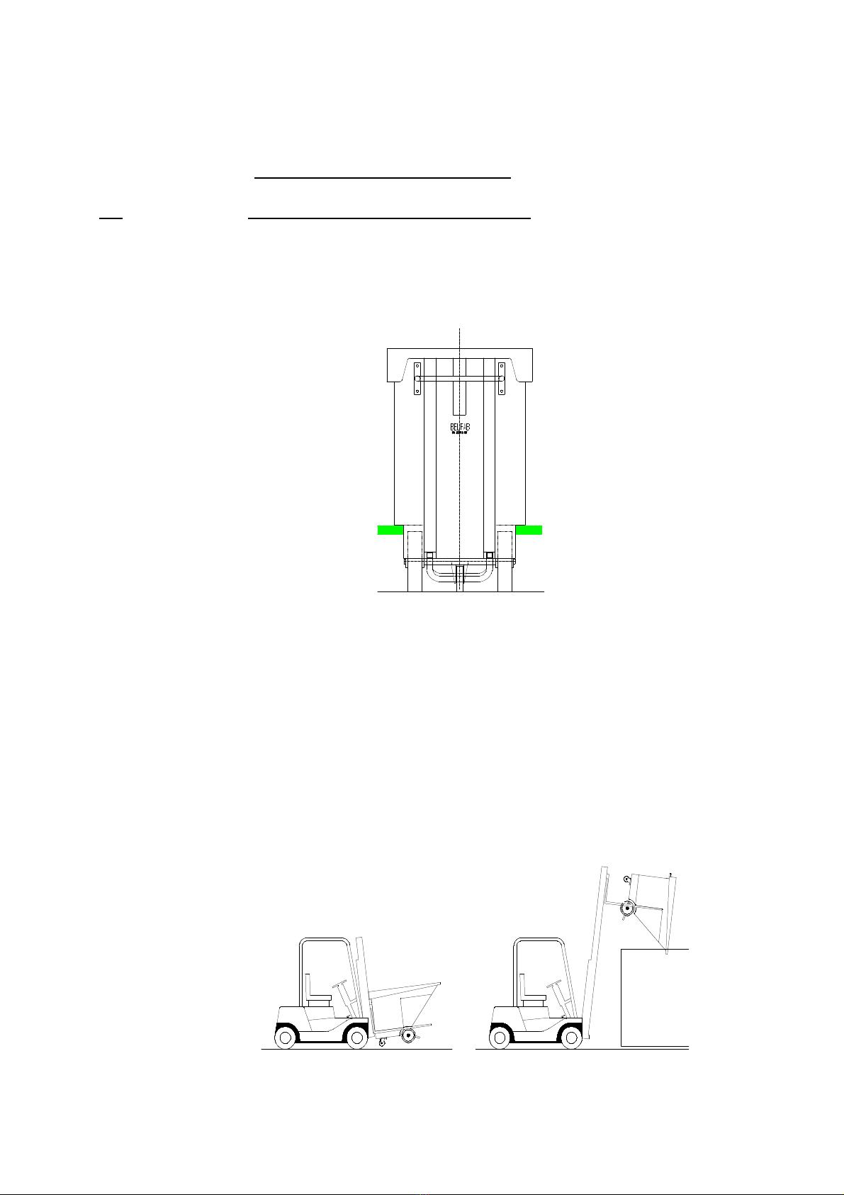
__ (OPTION) DUMPING BIN MANIPULATION
The bin has been designed not only to be moved and
emptied manually but also with the help of a fork lift. Simply
slide the forks under the lower shoulder as per shown
below.
For transportation, tilt the forks fully backward and lift until
bin wheels are off the ground. To dump, make sure the tip
of the forks will not hit the upper shoulder when the bin will
be tilted (total exceeding fork length may not be longer than
the vertical part of the shoulder . Keep the forks tilted
backward and elevate the bin as required. When positioned
and ready to dump, tilt the forks forward. You may have to
give the bin a boost, with an extending object, from
underneath (close to the swivel castor to initiate the
movement. If well positioned, the bin will rotate and
automatically stop in a perfect position to empty the load
completely.

10
MAINTENANCE
DU T COLLECTOR HOU ING
Protection against corrosion is required in the form of periodic repainting.
FAN IMPELLER AND MOTOR REMOVAL - IN TALLATION
The fan motor is bolted to a motor support plate. The impeller is installed
directly on the motor shaft. Unbolt and remove the piping installed at the fan
inlet. Remove the impeller from the motor shaft. Unbolt and remove the
motor from the motor support plate. For installation, reverse the above.
IN PECTION TO TAKE PLACE AFTER THE FIR T WEEK OF OPERATION
-Check the dust collector for filter bags failure and abrasion.
-During the first week of operation, check the storage section for waste
level and determine the emptying frequency that will be required.
EMI ANNUAL IN PECTION
-Lubricate all electric motors, exhaust fans, etc., as per manufacturer's
instructions.
-Check all filter bags for proper tension.
-Check the dust collector for filter bags failure and abrasion.

11
TROUBLE HOOTING GUIDE
1. Dust coming through the discharge of the unit:
•Check for improperly installed filter bags (be sure that the grooves on
the bi-benders are properly engaged in the hole sheet .
•Check for holes in filter bags.
2. Inadequate uction:
•Fan is running in wrong direction - Electrical wiring should be reversed.
•Forty-five (45 gallon storage drums or dumping bins are not sealed
properly – Adjust for proper seal.
•Filter bags are dirty - Clean or replace filter bags.
•Dampers or gates are closed - Open dampers or gates.
•Duct work is leaking or blocked - Repair or unblock ducts.
•Worn Impeller - Replace Impeller.
•The storage bin is full and the filter bags are blocked - Empty storage
and manually clean filter bags before restarting unit. DO NOT USE THE
SHAKER.
3. Unit is unduly noisy or has excessive vibration:
•Broken or damaged fan blade - Replace fan impeller.
•Fan is unbalanced - Check for wear or missing balance weight, if
applicable.
•Loose mounting bolts on unit - Tighten bolts.
•Loose fan impeller - Adjust and tighten.
•Loose guards - Tighten bolts.
•Bent shaft - Replace motor.

12
WARRANTY
Pyradia/Belfab is proud of the equipment which it manufactures. We have put
a great deal of thought, efforts and experience into the design and
construction of our units with the intention of providing you with the best
equipment for its purpose we know how to build. Experience indicates that if
you, the customer, will provide reasonable care and maintenance in the
operation of this equipment, it will provide you with a long, trouble-free,
reliable life.
Pyradia/Belfab warrants its equipment to be free from defects in material and
workmanship for a period of one year from the date of original shipment.
Without limiting what follows, Pyradia/Belfab will repair or replace (at its
discretion any such defective equipment or parts if they are returned to us
within the warranty period. However, the customer, must pay the
transportation cost. Should the customer require the inspection or work to be
done on his site by our qualified technicians, the customer will have to assume
the traveling expenses (mileage, traveling time and logging of the
technicians. Without limiting what follows, Pyradia/Belfab will assume the
labor to execute the repair to be done on site under warranty. To protect
yourself, you must let us know as soon as a problem arises, thereby avoiding
possible further damage.
Many parts in this equipment are normally replaced with use. Because these
parts may be easily damaged or consumed in normal operation, these parts
(such as straps, filter bags, filter cartridges, etc. are not covered by this
warranty. Nor does this warranty apply to equipment or components
manufactured by others (such as electric motors, starters, and other similar
items ; normally these items carry individual warranties of their own issued by
the original manufacturer. In the event of problems with third party
components (such as above , we will be pleased to help you obtain repair or
replacement and to advise you on installation.
If you have a problem, please contact us at once so we may promptly correct
the problem. Attempting your own repairs or operating the equipment in a
damaged condition may well make matters worse, and those resulting repairs
will unfortunately be at your own expense.
THI LIMITED WARRANTY I BEING MADE IN PLACE OF ALL OTHER
EXPRE WARRANTIE , AND IN PLACE OF ALL IMPLIED WARRANTIE OF
MERCHANTABILITY AND FITNE . THI LIMITED WARRANTY I IN LIEU OF
ALL OBLIGATION OR LIABILITIE ON THE PART OF PYRADIA/BELFAB FOR
DAMAGE , INCLUDING, BUT NOT LIMITED TO, CON EQUENTIAL AND
INCIDENTAL DAMAGE ARI ING OUT OF OR IN CONNECTION WITH THE U E
OF THI EQUIPMENT.

13
AVERTI EMENT
Assurez-vous que votre installation répond aux normes applicables selon les
autorités locales et les standards de NFPA qui sont disponibles auprès de la
National Fire Prevention Association.
Ces standards incluent, mais ne sont pas limités à:
- Standard for the Prevention of Fires and Dust Explosions in Agricultural and Food
Processing Facilities, NFPA 61
- Standard for Combustible Metals, Metal Powders and Metal Dusts, NFPA 484
- Standard for the Prevention of Fires and Explosions in Wood Processing and
Woodworking Facilities, NFPA 664
-
Standard for the Prevention of Fire and Dust Explosions from the Manufacturing,
Processing and Handling of Combustible Particulate Solids, NFPA 654
Notes pour la province de Québec
Les normes applicables au Québec incluent le RSST (Règlement sur la santé
et la sécurité du travail). Ci-dessous se trouve un extrait des principaux
points de l’article 59.1 applicable aux dépoussiéreurs ouverts installés à
l’intérieur, utilisés dans l’industrie du bois. Consulter le RSST pour
l’information complete (www.csst.qc.ca .
-
Le dépoussiéreur n'est pas relié à une ponceuse ou une raboteuse par abrasion à
alimentation mécanique
-
La capacité ne dépasse pas 2,4 mètres cube par seconde (5000 PCM
-Le dépoussiéreur est installé à au moins 6 mètres d'un poste de travail, d'une voie
de circulation ou d'une sortie de secours, à moins qu'un écran de protection contre la
déflagration, tel une feuille d'acier, une feuille en matériau synthétique résistant au
feu ou un mur de gypse, ne soit installé entre le poste, la voie ou la sortie et le
collecteur ouvert, si cette distance ne peut être respectée
-S’ il y a plus d'un collecteur ouvert, il doit y avoir au moins 6 mètres entre les
collecteurs, à moins qu'un écran de protection contre la déflagration, tel une feuille
d'acier, une feuille en matériau synthétique résistant au feu ou un mur de gypse, ne
soit installé entre les collecteurs, si cette distance ne peut être respectée
Prenez note qu’une installation non-conforme pourrait présenter des risques
d’incendie et d’explosion.
Ces informations sont valides en date de novembre 2008,
veuillez contacter BELFAB au 1-866-423-5322 pour des
informations complémentaires et plus récentes.

14
MI E EN GARDE
MÊME I VOTRE NOUVEL ÉQUIPEMENT E T CONÇU ET FABRIQUÉ AVEC
LE MEILLEURE COMPO ANTE PO IBLE , IL E T FORTEMENT
RECOMMANDÉ DE NE PA LAI ER L’ÉQUIPEMENT FONCTIONNER
AN URVEILLANCE AFIN D’ÉVITER TOUT DOMMAGE POTENTIEL
POUVANT URVENIR UITE À UNE DÉFAILLANCE D’UNE COMPO ANTE
OU D’UN MAUVAI RÉGLAGE DE L’OPÉRATEUR.
LA PRÉ ENCE UR L’ÉQUIPEMENT DE COMPO ANTE DE ÉCURITÉ
N’E T PA UNE GARANTIE AB OLUE D’UN FONCTIONNEMENT ÛR.
POUR UN FONCTIONNEMENT ÉCURITAIRE, RIEN NE REMPLACE UN
OPÉRATEUR BIEN ENTRAÎNÉ ET ATTENTIONNÉ.
PUI QUE EUL L’OPÉRATEUR CONNAÎT LE CONDITION RÉELLE
D’UTILI ATION DE L’ÉQUIPEMENT, IL E T DE VOTRE
RE PON ABILITÉ D’ÉTABLIR UN PROGRAMME D’IN PECTION /
ENTRETIEN ET D’EN RE PECTER LA FRÉQUENCE ET L’ÉTENDUE.

15
DE CRIPTION
La poussière aspirée par le ventilateur entre dans l'appareil par l’entrée situé
sur le côté du dépoussiéreur et pénètre dans la section de séparation primaire
où les grosses particules sont précipitées. La section immédiatement au-
dessus est la section de filtration secondaire où les particules fines sont
retenues dans les sacs de filtration.
Lorsque le ventilateur s'arrête, et que l'on secoue les sacs de filtration, les
rebuts tombent soi dans les barils de rétention, dans les chariots dompeurs
(option ou dans le système de transfert pneumatique (option .
Si le système optionnel de transfert de poussière pneumatique (incluant les
trémies modulaires et les ventilateurs est branché sur les modules de
filtration, la poussière sera continuellement transférée des trémies jusqu’au
conteneur externe fourni par le client.

16
IN TALLATION
ATTENTION : Assurez-vous que votre installation répond aux
normes applicables selon les autorités locales et les
standards de NFPA qui sont disponibles auprès de la
National Fire Prevention Association.
FONDATION ET E PACE REQUI
Le ventilateur et les modules de filtration doivent être installés sur une base
nivelée suffisamment grande et solide pour supporter le poids du
dépoussiéreur, y compris tous les accessoires. L’unité doit être ancré
adéquatement au sol à l’aide des pieds d’ancrage (foot pads soudés au bas
des pattes. Il faut allouer suffisamment d'espace pour brancher la tuyauterie
d'admission, la tuyauterie d'évacuation et pour effectuer facilement les travaux
de d'entretien et de réparation. Se référer au dessin 0948-DAB-00000 de
l’annexe 2.
LEVAGE
Levez le dépoussiéreur par le dessous. Ne jamais lever l'appareil par l'arbre
du ventilateur ou la sortie du ventilateur.
A EMBLAGE DE L’UNITÉ
Se référer au dessin 0886-BIB-00000 de l’annexe 2.
VENTILATEUR
Tourner manuellement la roue du ventilateur afin de s'assurer qu'elle tourne
librement. Alimenter le moteur un bref instant et vérifier le sens de rotation
de la roue du ventilateur. Si la roue tourne dans la mauvaise direction, appeler
un électricien pour inverser deux fils d’alimentation au moteur.
ÉLECTRIQUE
Protéger le moteur du ventilateur par des fusibles temporisés ayant une
capacité entre 125% et 150% de l’ampérage nominal indiqué sur la plaque
signalétique du moteur.
CONDUIT
Relier l’entrée du ventilateur aux points de succion en utilisant des conduits
rigides. Lorsque l’utilisation de tuyaux flexible est nécessaire, réduire sa
longueur au minimum.

17
IN TALLATION (suite)
BARIL DE RÉTENTION DE 45 GALLON
Fixer les manchons au-dessous du dépoussiéreur au moyen des collets de
serrage fixes et au-dessus des barils de rétention de 45 gallons au moyen des
collets de serrage à dégagement rapide.
CHARIOT DOMPEUR (option)
Fixer la plaque d’accouplement rapide en se référant au dessin 0482-AIF-
00000 de l’annexe 2. Pour vous aider, utiliser le chariot dompeur en suivant
les directives suivantes :
1. Glisser la plaque d’accouplement rapide sur le chariot dompeur, mais
sans aller jusqu’au fond. Laisser la plaque d’accouplement rapide
dépasser d’environ deux (2 pieds. Au besoin, demander de l’aide pour
retenir le chariot dompeur et l’empêcher de culbuter vers l’avant.
2. Rouler ensuite le chariot dompeur sous le module de filtration jusqu’à ce
que le repli vers le haut de la plaque d’accouplement arrive à égalité
avec le devant du module de filtration.
3. Fixer les boulons se trouvant à l’arrière de l’unité (là où la plaque
d’accouplement dépasse le module de filtration . Il n’est pas nécessaire
de serrer complètement les boulons à cette étape.
4. Lorsque les boulons à l’arrière sont posés, reculer le chariot dompeur
afin d’atteindre les trous situés au centre de la plaque d’accouplement
rapide.
5. Lorsque les quatre (4 boulons sont installés, sortir complètement le
chariot dompeur. Les deux (2 derniers boulons sont maintenant
accessibles et peuvent être installés.
6. Serrer adéquatement les six (6 boulons et vérifier l’étanchéité entre la
plaque d’accouplement rapide et l’unité de filtration.
Diriger ensuite le chariot dompeur dans la plaque d’accouplement rapide.
Le sol doit être relativement nivelé, pour que les roues du chariot ne
touchent plus au sol lorsqu’il est en position. Le chariot dompeur devrait
commencer à écraser le joint d’étanchéité lorsqu’il se trouve à environ six
(6 à douze (12 pouces de sa position finale au fond de la plaque
d’accouplement rapide. Si le joint d’étanchéité du chariot dompeur fuit
lorsque le dépoussiéreur est en fonction, descendre aux endroits
nécessaires les guides d’ajustement, cachés sous les rebords du chariot.
Noter que le scellement optimum est obtenu lorsque le joint d’étanchéité
est écrasé d’environ un huitième de pouce (1/8” . Un joint trop écrasé ne
scellera pas mieux, cela ne fera que diminuer sa durée de vie et pourrait
l’endommager de façon permanente.
This manual suits for next models
1
Table of contents
Languages:
Other belfab Dust Collector manuals


