Belimo LM24A-MOD Instruction Manual

Technical data sheet LM24A-MOD
www.belimo.com LM24A-MOD • en-gb • 2022-07-15 • Subject to change 1 / 7
Communicative damper actuator for
adjusting dampers in technical building
installations
• Air damper size up to approx.1m²
• Torque motor5Nm
• Nominal voltageAC/DC24V
• Controlmodulating, communicative, hybrid
• Conversion of sensor signals
• Communication via BACnet MS/TP, Modbus
RTU, Belimo-MP-Bus or conventional control
Technical data
Electrical data Nominal voltage AC/DC24V
Nominal voltage frequency 50/60Hz
Nominal voltage range AC19.2...28.8V/DC21.6...28.8V
Power consumption in operation 2.5 W
Power consumption in rest position 1.3 W
Power consumption for wire sizing 5 VA
Connection supply / control Cable 1m, 6 x 0.75mm²
Data bus communication Communicative control BACnet MS/TP
Modbus RTU (default setting)
MP-Bus
Number of nodes BACnet / Modbus see interface description
MP-Bus max. 8
Functional data Torque motor 5Nm
Torque variable 25%, 50%, 75% reduced
Operating range Y 2...10V
Operating range Y variable 0.5...10 V
Position feedback U 2...10V
Position feedback U note Max. 1 mA
Position feedback U variable Start point 0.5...8 V
End point 2...10 V
Position accuracy ±5%
Direction of motion motor selectable with switch 0/1
Direction of motion note Y = 0%: At switch position 0 (ccw rotation) / 1
(cw rotation)
Direction of motion variable electronically reversible
Manual override with push-button, can be locked
Angle of rotation Max.95°
Angle of rotation note can be limited on both sides with adjustable
mechanical end stops
Running time motor 150s / 90°
Running time motor variable 35...150s
Adaptation setting range manual
Adaptation setting range variable No action
Adaptation when switched on
Adaptation after pushing the manual override
button
Override control, controllable via bus
communication
MAX (maximum position) = 100%
MIN (minimum position) = 0%
ZS (intermediate position) = 50%

Technical data sheet LM24A-MOD
www.belimo.com LM24A-MOD • en-gb • 2022-07-15 • Subject to change 2 / 7
•
•
•
•
•
•
•
Mode of operation
Converter for sensors
Functional data Override control variable MAX = (MIN + 32%)...100%
MIN = 0%...(MAX – 32%)
ZS = MIN...MAX
Sound power level, motor 35dB(A)
Mechanical interface Universal shaft clamp 6...20mm
Position indication Mechanically, pluggable
Safety data Protection class IEC/EN III, Safety Extra-Low Voltage (SELV)
Power source UL Class 2 Supply
Degree of protection IEC/EN IP54
Degree of protection NEMA/UL NEMA2
Enclosure ULEnclosureType2
EMC CE according to 2014/30/EU
Certification IEC/EN IEC/EN60730-1 and IEC/EN60730-2-14
UL Approval cULus according to UL60730-1A, UL60730-2-14
and CAN/CSAE60730-1
The UL marking on the actuator depends on
the production site, the device is UL-compliant
in any case
Mode of operation Type 1
Rated impulse voltage supply / control 0.8kV
Pollution degree 3
Ambient humidity Max. 95% RH, non-condensing
Ambient temperature -30...50°C [-22...122°F]
Storage temperature -40...80°C [-40...176°F]
Servicing maintenance-free
Weight Weight 0.55kg
Safety notes
This device has been designed for use in stationary heating, ventilation and air-conditioning
systems and must not be used outside the specified field of application, especially in aircraft or
in any other airborne means of transport.
Outdoor application: only possible in case that no (sea) water, snow, ice, insolation or
aggressive gases interfere directly with the device and that it is ensured that the ambient
conditions remain within the thresholds according to the data sheet at any time.
Only authorised specialists may carry out installation. All applicable legal or institutional
installation regulations must be complied during installation.
The device may only be opened at the manufacturer's site. It does not contain any parts that
can be replaced or repaired by the user.
Cables must not be removed from the device.
To calculate the torque required, the specifications supplied by the damper manufacturers
concerning the cross-section, the design, the installation situation and the ventilation
conditions must be observed.
The device contains electrical and electronic components and must not be disposed of as
household refuse. All locally valid regulations and requirements must be observed.
Product features
The actuator is fitted with an integrated interface for BACnet MS/TP, Modbus RTU and MP-Bus.
It receives the digital control signal from the control system and returns the current status.
Connection option for a sensor (passive, active or with switching contact). In this way, the
analogue sensor signal can be easily digitised and transferred to the bus systems : BACnet,
Modbus or MP-Bus.

Technical data sheet LM24A-MOD
www.belimo.com LM24A-MOD • en-gb • 2022-07-15 • Subject to change 3 / 7
Parametrisable actuators
Combination analogue - communicative
(hybrid mode)
Simple direct mounting
Manual override
Adjustable angle of rotation
High functional reliability
Home position
Adaptation and synchronisation
The factory settings cover the most common applications. Single parameters can be modified
with the Belimo Service Tools MFT-P or ZTH EU.
The communication parameters of the bus systems (address, baud rate etc.) are set with the
ZTH EU. Pressing the "Address" button on the actuator while connecting the supply voltage,
resets the communication parameters to the factory setting.
Quick addressing: The BACnet and Modbus address can alternatively be set using the buttons
on the actuator and selecting 1...16. The value selected is added to the «Basic address»
parameter and results in the effective BACnet and Modbus address.
With conventional control by means of an analogue control signal, BACnet or Modbus can be
used for the communicative position feedback
Simple direct mounting on the damper shaft with a universal shaft clamp, supplied with an anti-
rotation device to prevent the actuator from rotating.
Manual override with push-button possible (the gear train is disengaged for as long as the
button is pressed or remains locked).
Adjustable angle of rotation with mechanical end stops.
The actuator is overload protected, requires no limit switches and automatically stops when the
end stop is reached.
The first time the supply voltage is switched on, i.e. at the time of commissioning, the actuator
carries out a synchronisation. The synchronisation is in the home position (0%).
The actuator then moves into the position defined by the control signal.
An adaptation can be triggered manually by pressing the "Adaptation" button or with the PC-
Tool. Both mechanical end stops are detected during the adaptation (entire setting range).
Automatic synchronisation after pressing the manual override button is configured. The
synchronisation is in the home position (0%).
The actuator then moves into the position defined by the control signal.
A range of settings can be adapted using the PC-Tool (see MFT-P documentation)
Accessories
Electrical accessories Description Type
Auxiliary switch 1 x SPDT add-on S1A
Auxiliary switch 2 x SPDT add-on S2A
Feedback potentiometer 140 Ω add-on P140A
Feedback potentiometer 200 Ω add-on P200A
Feedback potentiometer 500 Ω add-on P500A
Feedback potentiometer 1 kΩ add-on P1000A
Feedback potentiometer 2.8 kΩ add-on P2800A
Feedback potentiometer 5 kΩ add-on P5000A
Feedback potentiometer 10 kΩ add-on P10000A
Technical data sheet LM24A-MOD
www.belimo.com LM24A-MOD • en-gb • 2022-07-15 • Subject to change 4 / 7
Mechanical accessories Description Type
Shaft extension 170 mm Ø10 mm for damper shaft Ø 6...16 mm AV6-20
Shaft clamp one-sided, clamping range Ø6...20 mm, Multipack 20 pcs. K-ELA
Shaft clamp one-sided, clamping range Ø6...10 mm, Multipack 20 pcs. K-ELA10
Shaft clamp one-sided, clamping range Ø6...13 mm, Multipack 20 pcs. K-ELA13
Shaft clamp one-sided, clamping range Ø6...16 mm, Multipack 20 pcs. K-ELA16
Anti-rotation mechanism 180 mm, Multipack 20 pcs. Z-ARS180
Form fit insert 8x8mm, Multipack 20 pcs. ZF8-LMA
Form fit insert 10x10mm, Multipack 20 pcs. ZF10-LMA
Form fit insert 12x12mm, Multipack 20 pcs. ZF12-LMA
Form fit insert 8x8mm, with angle of rotation limiter and position
indication, Multipack 20 pcs.
ZFRL8-LMA
Form fit insert 10x10mm, with angle of rotation limiter and position
indication, Multipack 20 pcs.
ZFRL10-LMA
Form fit insert 12x12mm, with angle of rotation limiter and position
indication, Multipack 20 pcs.
ZFRL12-LMA
Position indicator, Multipack 20 pcs. Z-PI
Tools Description Type
Service Tool, with ZIP-USB function, for parametrisable and
communicative Belimo actuators, VAV controller and HVAC performance
devices
ZTH EU
Belimo PC-Tool, Software for adjustments and diagnostics MFT-P
Adapter for Service-Tool ZTH MFT-C
Connection cable 5 m, A: RJ11 6/4 ZTH EU, B: 6-pin for connection to
service socket
ZK1-GEN
Connection cable 5 m, A: RJ11 6/4 ZTH EU, B: free wire end for connection
to MP/PP terminal
ZK2-GEN
Electrical installation
Supply from isolating transformer.
The wiring of the line for BACnet MS/TP / Modbus RTU is to be carried out in accordance with
applicable RS-485 regulations.
Modbus / BACnet: Supply and communication are not galvanically isolated. Connect earth signal
of the devices with one another.
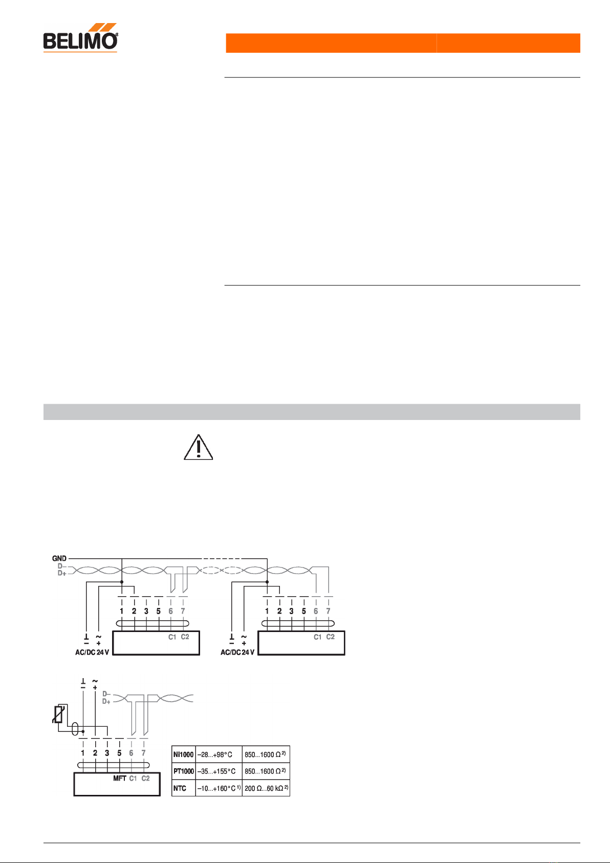
Wiring diagrams
BACnet MS/TP / Modbus RTU
Cable colours:
1= black
2 = red
3 = white
5 = orange
6 = pink
7 = grey
BACnet / Modbus signal
assignment:
C1 = D– = A
C2 = D+ = B
Connection with passive sensor, e.g. Pt1000, Ni1000, NTC
1) depending on type
2) Resolution 1 Ohm
Compensation of the measured
value is recommended

Technical data sheet LM24A-MOD
www.belimo.com LM24A-MOD • en-gb • 2022-07-15 • Subject to change 5 / 7
Connection with active sensor, e.g. 0...10 V @ 0...50°C
Possible voltage range:
0...32 V (resolution 30 mV)
Connection with switching contact, e.g. Δp monitor
Requirements for switching
contact:
The switching contact must be
able to accurately switch a
current of 16 mA @ 24 V.
Modbus RTU / BACnet MS/TP with analogue setpoint (hybridmode)
Operation on the MP-Bus

Technical data sheet LM24A-MOD
www.belimo.com LM24A-MOD • en-gb • 2022-07-15 • Subject to change 6 / 7
Quick addressing
Operating controls and indicators
Direction of rotation switch
Switch over: Direction of rotation changes
Push-button and LED display green
Off: No power supply or malfunction
On: In operation
Flashing: In address mode: Pulses according to set address (1...16)
When starting: Reset to factory setting (Communication)
Press button: In standard mode: Triggers angle of rotation adaptation
In address mode: Confirmation of set address (1...16)
Push-button and LED display yellow
Off: Standard mode
On: Adaptation or synchronisation process active
or actuator in address mode (LED display green flashing)
Flickering: BACnet / Modbus communication active
Press
button:
In operation (>3 s): Switch address mode on and off
In address mode: Address setting by pressing several times
When starting (>5 s): Reset to factory setting (Communication)
Manual override button
Press button: Gear train disengages, motor stops, manual override possible
Release
button:
Gear train engages, synchronisation starts, followed by standard
mode
Service plug
For connecting parametrisation and service tools
Check power supply connection
Off and On Possible wiring error in power supply
Service
1. Press the "Address" button until the green "Power" LED is no longer illuminated. LED flashes
in accordance with the previously set address.
2. Set the address by pressing the "Address" button the corresponding number of times (1...16).
3. The green LED flashes in accordance with the address that has been entered (...16). If the
address is not correct, then this can be reset in accordance with Step 2.
4. Confirm the address setting by pressing the green "Adaptation" button.
If no confirmation occurs for 60 seconds, then the address procedure is ended. Any address
change that has already been started will be discarded.
The resulting BACnet MS/TP and Modbus RTU address is made up of the set basic address plus
the short address (e.g. 100+7=107).
1
2
3
4
5
2 3

Technical data sheet LM24A-MOD
www.belimo.com LM24A-MOD • en-gb • 2022-07-15 • Subject to change 7 / 7
Tools connection The actuator can be parametrised by ZTH EU via the service socket.
For an extended parametrisation the PC tool can be connected.
Dimensions
Spindle length
Min. 37
-
Clamping range
Further documentation
• Tool connections
• BACnet Interface description
• Modbus Interface description
• Overview MP Cooperation Partners
• MP Glossary
• Introduction to MP-Bus Technology
Application notes
• For digital control of actuators in VAV applications patent EP 3163399 must be considered.
Table of contents
Other Belimo Industrial Equipment manuals


Popular Industrial Equipment manuals by other brands

3M
3M 3M-Matic Accuglide NPH 11200 Instructions and parts list

Schier
Schier GB-500 installation guide

Matsusada Precision
Matsusada Precision PZJE Series instruction manual

Hitachi
Hitachi Relion REL670 Product guide

3M
3M Liqui-Cel EXF-14 28 Series Assembly and disassembly instructions

LMI Technologies
LMI Technologies MikroCAD quick start guide


