manuals.online logo
Brands
  1. Home
  2. •
  3. Brands
  4. •
  5. Eaton
  6. •
  7. Industrial Equipment
  8. •
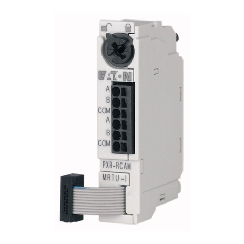
  9. Eaton Magnum MRR1000 User manual

Eaton Magnum MRR1000 User manual

Other manuals for Magnum MRR1000

1

Other Eaton Industrial Equipment manuals
Eaton Power Xpert XP2 User manual

Eaton

Eaton Power Xpert XP2 User manual

Eaton NZM2-XKSA Manual

Eaton

Eaton NZM2-XKSA Manual

Eaton MMX-NET-XA Manual

Eaton

Eaton MMX-NET-XA Manual

Eaton DILP-XHB Series Manual

Eaton

Eaton DILP-XHB Series Manual

Eaton NZM1-XBR Manual

Eaton

Eaton NZM1-XBR Manual

Eaton XTSE Series Manual

Eaton

Eaton XTSE Series Manual

Eaton EMS-2 Manual

Eaton

Eaton EMS-2 Manual

Eaton EU1H-SWD Series Manual

Eaton

Eaton EU1H-SWD Series Manual

Eaton NZM4-XKV95-2KB Manual

Eaton

Eaton NZM4-XKV95-2KB Manual

Eaton BBAOC-16 Manual

Eaton

Eaton BBAOC-16 Manual

Eaton P3-30/EA/SVB-MCS Manual

Eaton

Eaton P3-30/EA/SVB-MCS Manual

Eaton Airflex WCBD Series User manual

Eaton

Eaton Airflex WCBD Series User manual
Eaton NN-GW-100-LAN User manual

Eaton

Eaton NN-GW-100-LAN User manual

Eaton NZM4-XKSFA Manual

Eaton

Eaton NZM4-XKSFA Manual

Eaton RPR-2 User manual

Eaton

Eaton RPR-2 User manual

Eaton Airflex VC 5000 Installation and operating instructions

Eaton

Eaton Airflex VC 5000 Installation and operating instructions

Eaton NZM3-XK22 21 Series Manual

Eaton

Eaton NZM3-XK22 21 Series Manual

Eaton PKE12 Series Manual

Eaton

Eaton PKE12 Series Manual

Eaton DX-BR Series Manual

Eaton

Eaton DX-BR Series Manual

Eaton NZMB2-A Series Manual

Eaton

Eaton NZMB2-A Series Manual

Eaton M22-ADC Manual

Eaton

Eaton M22-ADC Manual

Eaton GROUSE-HINDS AB 05 Ex-nR User manual

Eaton

Eaton GROUSE-HINDS AB 05 Ex-nR User manual

Eaton NZM-XSWD-704 Manual

Eaton

Eaton NZM-XSWD-704 Manual

Eaton MSFB Series Manual

Eaton

Eaton MSFB Series Manual

Popular Industrial Equipment manuals by other brands

ABB +Q957 user manual

ABB

ABB +Q957 user manual

G.B.C BASIC EDGE 50 instruction manual

G.B.C

G.B.C BASIC EDGE 50 instruction manual

Tronair Batpak 11-6602-1000 Operation & service manual

Tronair

Tronair Batpak 11-6602-1000 Operation & service manual

Pilz PNOZ mi2p Operation manual

Pilz

Pilz PNOZ mi2p Operation manual

Clemco Zero BNP 6012 manual

Clemco

Clemco Zero BNP 6012 manual

Erskine Attachments V-Plow Operator's manual

Erskine Attachments

Erskine Attachments V-Plow Operator's manual

ABB HT610965 Operation manual

ABB

ABB HT610965 Operation manual

Morra MH 540 user manual

Morra

Morra MH 540 user manual

GRIGGIO G 240 P4 instructions

GRIGGIO

GRIGGIO G 240 P4 instructions

Nexen AIR CHAMP HT45 user manual

Nexen

Nexen AIR CHAMP HT45 user manual

WTE V5 installation manual

WTE

WTE V5 installation manual

ABB HT845232 Operation manual

ABB

ABB HT845232 Operation manual

SMC Networks CJP Series Operation manual

SMC Networks

SMC Networks CJP Series Operation manual

JohnDow Industries JDI-AFT58 Operator's manual

JohnDow Industries

JohnDow Industries JDI-AFT58 Operator's manual

IMB MB9016A instruction manual

IMB

IMB MB9016A instruction manual

Clarke CUMB1 Assembly & operating instructions

Clarke

Clarke CUMB1 Assembly & operating instructions

amiad Arkal Spin Klin 2 user guide

amiad

amiad Arkal Spin Klin 2 user guide

Maxima GIUNTOMAX Use and maintenance manual

Maxima

Maxima GIUNTOMAX Use and maintenance manual

manuals.online logo
manuals.online logoBrands
  • About & Mission
  • Contact us
  • Privacy Policy
  • Terms and Conditions

Copyright 2025 Manuals.Online. All Rights Reserved.

Instruction
Booklet
IB
01900004
E
Effective
March
2011
Magnum
Breaker
Remote
Racking
Device
(
MRR
1000
)
Contents
Description
1
:
Introduction
2
:
Safe
Practices
3
:
Receiving
,
Handling
,
and
Storage
4
:
Procedures
5
:
Warranty
6
:
Troubleshooting
7
:
Publications
Page
3
5
5
6
12
12
12
F
:
T
*
M
Powering
Business
Worldwide
Courtesy of store.ips.us
Magnum
Breaker
Remote
Racking
Device
(
MRR
1000
)
Instruction
Booklet
IB
01900004
E
Effective
March
2011
A
NOTICE
This
product
is
manufactured
by
Eaton
Corporation
at
the
Asheville
Assemblies
Plant
:
221
Heywood
Road
,
Arden
,
NC
28704
.
All
possible
contingencies
which
may
arise
during
installation
,
opera
-
tion
or
maintenance
,
and
all
details
and
variations
of
this
equipment
do
not
purport
to
be
covered
by
these
instructions
.
If
further
infor
-
mation
is
desired
by
purchaser
regarding
his
particular
installation
,
operation
or
maintenance
of
particular
equipment
,
contact
an
Eaton
sales
or
service
representative
.
ALL
USERS
OF
THIS
PRODUCT
SHOULD
READ
AND
FOLLOW
THE
INSTRUCTIONS
PROVIDED
HEREIN
;
HOWEVER
,
THIS
INSTRUCTION
BOOK
SHOULD
NOT
BE
CONSIDERED
ALL
INCLUSIVE
REGARDING
INSTALLATION
OR
MAINTENANCE
PROCEDURES
.
IF
FURTHER
INFORMATION
IS
REQUIRED
,
YOU
SHOULD
CONSULT
EATON
'
S
ELECTRICAL
SERVICES
&
SYSTEMS
.
READ
AND
UNDERSTAND
THIS
AND
OTHER
SUPPLIED
INSTRUCTIONS
AND
DRAWINGS
IN
THEIR
ENTIRETY
BEFORE
INSTALLING
OR
OPERATING
THIS
DEVICE
.
ADJUSTMENT
,
REPAIR
OR
MAINTENANCE
,
OTHER
THAN
THOSE
DESCRIBED
HEREIN
,
MUST
BE
PERFORMED
BY
QUALIFIED
PERSONNEL
.
A
QUALIFIED
PERSON
IS
ONE
WHO
IS
FAMILIAR
WITH
THE
CONSTRUCTION
AND
OPERATION
OF
THIS
EQUIPMENT
AND
THE
HAZARDS
INVOLVED
.
A
WARNING
IMPROPER
USE
OR
MAINTENANCE
OF
THIS
PRODUCT
,
OR
OPERATING
IT
IN
A
MANNER
FOR
WHICH
IT
WAS
NOT
INTENDED
,
MAY
RESULT
IN
DEATH
,
SERIOUS
PERSONAL
INJURY
OR
PROPERTY
DAMAGE
.
READ
AND
UNDERSTAND
THESE
INSTRUCTIONS
BEFORE
ATTEMPTING
ANY
OPERATION
OR
MAINTENANCE
OF
THE
CIRCUIT
BREAKERS
TO
BE
OPERATED
BY
THIS
DEVICE
THE
CIRCUIT
BREAKERS
DESCRIBED
IN
THIS
MANUAL
ARE
DESIGNED
AND
TESTED
TO
OPERATE
WITHIN
THEIR
NAMEPLATE
RATINGS
.
OPERATION
OUTSIDE
OF
THESE
RATINGS
MAY
CAUSE
THE
EQUIPMENT
TO
FAIL
,
RESULTING
IN
DEATH
,
BODILY
INJURY
OR
PROPERTY
DAMAGE
.
ALL
SAFETY
CODES
,
SAFETY
STANDARDS
AND
/
OR
REGULATIONS
AS
THEY
MAY
BE
APPLIED
TO
THIS
TYPE
OF
EQUIPMENT
MUST
BE
STRICTLY
ADHERED
TO
.
A
NOTICE
THE
DANGER
,
WARNING
AND
CAUTION
MESSAGES
INCLUDED
AS
A
PART
OF
THE
PROCEDURAL
STEPS
IN
THIS
MANUAL
ARE
FOR
PERSONNEL
SAFETY
AND
PROTECTION
OF
EQUIPMENT
FROM
DAMAGE
.
AN
EXAMPLE
OF
A
TYPICAL
WARNING
LABEL
HEADING
IS
SHOWN
ABOVE
THIS
PARAGRAPH
TO
FAMILIARIZE
PERSONNEL
WITH
THIS
TYPE
OF
PRESENTATION
.
THIS
WILL
HELP
ASSURE
THAT
PERSONNEL
ARE
ALERT
TO
THESE
TYPE
MESSAGES
.
IN
ADDITION
,
THESE
MESSAGES
ARE
ALL
UPPER
CASE
AND
BOLDFACE
.
EATON
CORPORATION
www
.
eaton
.
com
2
Courtesy of store.ips.us
Magnum
Breaker
Remote
Racking
Device
(
MRR
1000
)
Instruction
Booklet
IB
01900004
E
Effective
March
2011
Section
1
:
Introduction
Eaton
'
s
MRR
1000
provides
a
means
of
remotely
inserting
or
remov
-
ing
any
drawout
circuit
breaker
in
the
Magnum
DS
®
family
of
Power
Circuit
Breakers
(
PCBs
)
.
In
addition
,
the
MRR
1000
enables
the
operator
to
remotely
open
and
close
any
Magnum
DS
circuit
breaker
utilizing
the
pushbuttons
on
the
face
of
the
breaker
.
Increased
safety
precautions
and
the
need
to
protect
personnel
from
the
dan
-
gers
of
potential
arc
flash
occurrences
suggest
the
need
to
increase
the
distance
between
an
operator
and
the
front
of
a
switchgear
or
switchboard
during
racking
operations
.
With
the
MRR
1000
,
an
operator
can
be
up
to
25
feet
away
from
the
breaker
compartment
door
during
the
rack
-
in
or
rack
-
out
process
.
Electric
arcs
result
from
thermal
ionization
that
occurs
when
current
flow
is
interrupted
by
the
separation
of
conductors
.
Thermal
ioniza
-
tion
can
generate
temperatures
as
high
as
35
,
000
°
F
Conductor
materials
melt
into
metal
vapor
and
the
surrounding
air
is
ionized
.
If
the
arc
is
external
of
the
interrupting
chamber
of
a
power
circuit
breaker
,
then
a
violent
explosion
occurs
resulting
in
an
inferno
of
ionized
gases
,
molten
debris
,
metal
shrapnel
,
and
a
flash
of
light
(
arc
flash
)
.
When
arc
flash
initiates
within
a
switchgear
/
switchboard
cabi
-
net
,
the
rapidly
escalating
pressure
can
dislodge
compartment
doors
and
side
sheets
of
the
switchgear
and
turn
hardware
into
high
-
speed
projectiles
.
Arc
flash
levels
are
a
function
of
circuit
voltage
,
maximum
available
short
circuit
current
at
the
point
of
flashover
,
conditions
of
confine
-
ment
,
and
the
distance
between
the
point
of
flashover
and
the
point
of
measurement
.
Operating
personnel
are
typically
within
two
feet
of
the
front
of
the
power
circuit
breaker
during
the
racking
process
.
In
the
event
of
an
arc
flash
event
,
this
close
proximity
could
cause
serious
injury
or
death
.
NFPA
70
E
provides
guidance
for
the
requirements
of
person
-
al
protective
equipment
(
PPE
)
to
protect
personnel
from
the
dangers
of
arc
flash
exposure
.
PPE
for
high
levels
of
arc
flash
can
be
bulky
,
hot
and
uncomfortable
.
This
may
dissuade
personnel
from
wearing
proper
protection
.
The
best
way
to
limit
exposure
to
arc
flash
during
the
process
of
racking
Power
Circuit
Breakers
is
to
put
more
dis
-
tance
between
the
person
and
the
possible
point
of
exposure
.
Eaton
'
s
remote
racking
device
fulfills
the
objective
of
increased
worker
safety
by
permitting
routine
operations
from
an
increased
distance
from
the
power
circuit
breaker
.
1.1
Compatibility
The
remote
racking
device
is
compatible
with
any
drawout
breaker
in
the
Magnum
DS
family
of
Power
Circuit
Breakers
(
PCBs
)
.
This
includes
the
Magnum
DS
standard
frame
,
narrow
frame
and
double
-
wide
frame
rated
for
switchgear
(
ANSI
)
,
Magnum
SB
switchboard
class
and
IEC
60947
-
2
applications
;
as
well
as
CM
52
network
pro
-
tector
breakers
.
The
application
may
be
used
while
enclosed
in
Magnum
DS
Low
-
Voltage
Switchgear
and
Switchboards
with
the
breaker
compartment
door
closed
.
The
MRR
1000
is
also
compatible
with
Magnum
DS
ARC
Resistant
Switchgear
and
also
compatible
with
Magnum
DS
family
of
drawout
PCBs
in
other
OEM
installa
-
tions
.
A
CAUTION
THE
CASE
DIMENSIONS
,
RETENTION
METHOD
AND
OPERATING
MECHA
-
NISM
OF
THE
MRR
1000
ARE
DESIGNED
TO
WORK
EXCLUSIVELY
WITH
THE
MAGNUM
DS
FAMILY
OF
PCBS
.
ANY
ATTEMPT
TO
USE
THE
DEVICE
WITH
ANOTHER
MANUFACTURER
'
S
BREAKER
WILL
PUT
THE
OPERATOR
AT
RISK
OF
INJURY
AND
WILL
VOID
THE
WARRANTY
.
Unlike
some
remote
operating
devices
,
the
MRR
1000
requires
no
additional
mounting
kit
on
the
body
of
the
circuit
breaker
or
on
the
surface
of
the
switchgear
/
switchboard
.
In
fact
,
no
modification
or
additional
tools
are
required
.
The
MRR
1000
utilizes
features
found
on
every
breaker
of
the
Magnum
DS
family
,
making
it
convenient
to
install
and
use
.
ADANGER
WHEN
SWITCHGEAR
IS
CERTIFIED
TO
BE
ARC
RESISTANT
PER
ANSI
C
37.20
.
7
,
THE
ARC
RESISTANT
RATING
IS
ONLY
VALID
WHEN
ALL
DOORS
ARE
CLOSED
AND
PROPERLY
LATCHED
OR
BOLTED
,
AND
ALL
COMPONENTS
ARE
INSTALLED
AND
WORKING
PROPERLY
.
IN
ADDITION
,
REMOVAL
OF
ANY
BREAKER
FROM
ITS
CELL
WITHOUT
REINSTALLING
A
BREAKER
OR
ARC
RESISTANT
PROVISION
COVER
WILL
VOID
THE
ARC
RESISTANT
RATING
.
FOR
COMPLETE
INSTRUCTIONS
REGARDING
ARC
RESISTANT
SWITCHGEAR
,
SEE
IB
01900001
E
,
LISTED
IN
SECTION
7
.
EATON
CORPORATION
www
.
eaton
.
com
3
Courtesy of store.ips.us
Magnum
Breaker
Remote
Racking
Device
(
MRR
1000
)
Instruction
Booklet
IB
01900004
E
Effective
March
2011
12.60
[
320
1
J
1
$
.
13
[
304.3
]
0
rN
0
02
o
I
a
B
o
6
O
o
1503
EffioET
Mm
®
®
®
sab
.
_
o
[
361
8
]
y
CD
.
o
o
o
o
CP
n
T
n
[
o
A
7
06
(
170.3
)
”
A
'
‘
“
A
"
Shaft
inch
(
mm
)
"
B
”
Handle
Inch
(
mm
)
Retracted
Position
4.28
(
108.71
)
2.75
(
69.85
)
Extended
Position
2.28
(
57.91
)
4.75
(
120.65
)
LOCKING
HANDLE
LOCKING
PIN
NEOPRENE
LOCK
FACEPLATE
DISPLAY
SHAFT
/
CLUTCH
ASSEMBLY
SHAFT
/
MOTOR
HANDLE
EATON
CORPORATION
www
.
eaton
.
com
4
Courtesy of store.ips.us
Magnum
Breaker
Remote
Racking
Device
(
MRR
1000
)
Instruction
Booklet
IB
01900004
E
Effective
March
2011
Section
2
:
Safe
Practices
for
Power
Circuit
Breakers
The
Magnum
DS
family
of
Power
Circuit
Breakers
are
equipped
with
high
speed
,
stored
energy
operating
mechanisms
.
They
are
designed
with
several
built
-
in
interlocks
and
safety
features
to
provide
safe
and
proper
operating
sequences
.
Section
3
:
Receiving
,
Handling
,
and
Storage
Magnum
Remote
Racking
Device
(
MRRtOOO
)
units
are
subjected
to
complete
factory
production
tests
and
inspection
before
being
packed
.
They
are
shipped
in
containers
designed
to
provide
maxi
-
mum
protection
to
the
equipment
during
shipment
and
storage
and
at
the
same
time
to
provide
convenient
handling
.
3.1
Receiving
Until
the
MRR
1000
unit
is
ready
to
be
delivered
to
the
point
of
use
,
do
not
remove
it
from
the
shipping
box
.
If
the
unit
is
to
be
placed
in
storage
for
an
extended
period
,
maximum
protection
can
be
obtained
by
keeping
it
in
its
box
.
Upon
receipt
of
the
equipment
,
inspect
the
box
for
any
signs
of
damage
or
rough
handling
.
Open
the
box
carefully
to
avoid
any
dam
-
age
to
the
contents
.
Use
care
when
using
a
box
cutter
or
similar
sharp
object
so
as
not
to
damage
contents
.
The
AC
power
cord
and
remote
pendant
control
cord
can
be
damaged
by
a
sharp
object
.
When
opening
the
container
,
be
careful
that
any
loose
items
or
hardware
are
not
discarded
with
the
packing
material
.
Check
the
contents
of
each
package
against
the
packing
list
.
Examine
the
MRR
1000
unit
for
any
signs
of
shipping
damage
such
as
broken
,
missing
or
loose
hardware
,
damaged
or
deformed
com
-
ponents
.
File
claims
immediately
with
the
carrier
if
damage
or
loss
is
detected
and
notify
the
nearest
Eaton
'
s
Electrical
Service
and
Systems
Office
.
3.2
Handling
The
MRR
1000
unit
shipping
containers
are
not
designed
to
be
handled
by
a
fork
lift
truck
.
If
containers
must
be
moved
for
any
sig
-
nificant
distance
,
it
is
suggested
to
use
a
suitable
dolly
or
hand
truck
to
move
the
approximately
40
lb
(
18
kg
)
package
.
3.3
Storage
Because
of
electric
circuits
inside
the
unit
,
as
well
as
moving
parts
,
it
is
essential
to
keep
the
remote
racking
device
dry
at
all
times
.
If
exposed
to
water
or
rain
,
performance
of
the
device
cannot
be
guar
-
anteed
and
will
void
the
warranty
.
If
the
unit
is
to
be
placed
in
stor
-
age
,
attention
should
be
given
to
keeping
the
unit
in
a
low
humidity
environment
.
Ensure
the
unit
is
free
from
damage
and
is
satisfac
-
tory
operating
condition
prior
to
storage
.
3.4
MRR
1000
Approximate
Weights
A
WARNING
TO
PROTECT
THE
PERSONNEL
ASSOCIATED
WITH
INSTALLATION
,
OPERATION
,
AND
MAINTENANCE
OF
THESE
BREAKERS
,
THE
FOLLOWING
PRACTICES
MUST
BE
FOLLOWED
:
•
ONLY
QUALIFIED
PERSONS
,
AS
DEFINED
IN
THE
NATIONAL
ELECTRICAL
SAFETY
CODE
,
WHO
ARE
FAMILIAR
WITH
THE
INSTALLATION
AND
MAINTENANCE
OF
LOW
VOLTAGE
CIRCUITS
AND
EQUIPMENT
,
SHOULD
BE
PERMITTED
TO
WORK
ON
THESE
BREAKERS
.
•
ALWAYS
REMOVE
THE
BREAKER
FROM
THE
ENCLOSURE
BEFORE
PERFORMING
ANY
MAINTENANCE
.
FAILURE
TO
DO
SO
COULD
RESULT
IN
ELECTRICAL
SHOCK
LEADING
TO
DEATH
,
SEVERE
PERSONNEL
INJU
-
RY
OR
PROPERTY
DAMAGE
.
•
DO
NOT
WORK
ON
A
CLOSED
BREAKER
OR
A
BREAKER
WITH
CLOSING
SPRINGS
CHARGED
.
THE
CLOSING
SPRING
SHOULD
BE
DISCHARGED
AND
THE
MAIN
CONTACTS
OPEN
BEFORE
WORKING
ON
THE
BREAKER
.
FAILURE
TO
DO
SO
COULD
RESULT
IN
CUTTING
OR
CRUSHING
INJUR
-
IES
.
•
BREAKERS
ARE
EQUIPPED
WITH
SAFETY
INTERLOCKS
.
DO
NOT
DEFEAT
THEM
.
THIS
MAY
RESULT
IN
DEATH
,
BODILY
INJURY
OR
EQUIPMENT
DAMAGE
.
NOTICE
FOR
COMPLETE
INSTRUCTIONS
ON
INSTALLATION
,
OPERATION
AND
MAINTENANCE
OF
THE
MAGNUM
DS
FAMILY
OF
CIRCUIT
BREAKERS
,
REFER
TO
THE
PUBLICATIONS
LISTED
IN
SECTION
7
OF
THIS
DOCUMENT
.
Unit
Type
Weight
MRR
1000
Breaker
Mounting
Unit
33
lbs
15
kgs
MRR
1000
Packaged
for
Shipment
40
lbs
18
kgs
EATON
CORPORATION
www
.
eaton
.
com
5
Courtesy of store.ips.us
Magnum
Breaker
Remote
Racking
Device
(
MRR
1000
)
Instruction
Booklet
IB
01900004
E
Effective
March
2011
Section
4
:
Procedures
4.1
General
Magnum
DS
Switchgear
and
Switchboard
enclosures
utilize
a
"
Thru
-
the
-
Door
"
racking
method
that
increases
operator
safety
when
inserting
or
removing
Power
Circuit
Breakers
.
The
MRR
1000
permits
operation
while
the
breaker
compartment
door
remains
closed
,
even
in
Arc
Resistant
enclosures
.
However
,
in
some
OEM
supplied
enclosures
,
"
Thru
-
the
-
Door
"
racking
may
not
be
possible
.
The
MRR
1000
is
fully
functional
and
not
reliant
on
the
presence
or
absence
of
a
door
to
operate
.
However
,
for
the
purposes
of
this
instruction
,
it
will
be
assumed
the
breaker
compartment
door
is
closed
.
Follow
all
procedures
defined
by
the
using
company
'
s
Personal
Protective
Equipment
and
Safety
Policy
.
Follow
all
precautions
and
requirements
listed
in
the
installation
,
operating
and
maintenance
instructions
of
the
subject
circuit
breakers
.
4.2
Unpacking
-
Preparations
for
Use
1
.
Remove
all
packing
materials
,
unwind
power
cord
and
pendant
control
cord
.
2
.
Obtain
120
V
AC
power
.
Use
of
a
standard
extension
cord
is
per
-
missible
with
a
minimum
of
6
amp
current
capacity
.
3
.
Connecting
power
to
the
unit
will
activate
the
"
READY
"
light
on
the
faceplate
(
there
is
no
"
on
/
off
"
switch
)
.
However
,
no
opera
-
tion
will
begin
until
use
of
pendant
buttons
as
described
in
Steps
4.3
.
3
and
4.4
.
3
,
below
.
4.3
Procedure
for
Removing
a
Power
Circuit
Breaker
4.3
.
1
Installation
on
the
Circuit
Breaker
Face
1
.
The
face
of
a
typical
Magnum
DS
Circuit
Breaker
is
shown
in
Figure
1
.
Note
the
small
recessed
cavity
in
the
upper
right
hand
corner
.
This
cavity
is
the
principal
element
for
retention
of
the
MRR
1000
-
ensure
this
cavity
is
free
from
contaminants
such
as
dust
,
grease
or
oil
.
2
.
Ensure
the
shaft
/
motor
assembly
is
in
the
rear
-
most
position
.
Pull
the
handle
attached
to
the
shaft
/
motor
assembly
firmly
rear
-
ward
to
verify
the
assembly
is
seated
in
the
rear
detent
.
3
.
Ensure
the
locking
handle
is
in
the
unlocked
position
(
Figure
2
)
.
If
the
handle
is
in
the
locked
position
,
pull
out
on
the
locking
pin
as
shown
to
release
the
handle
.
4
.
Lift
the
MRR
1000
to
the
level
of
the
selected
Power
Circuit
Breaker
.
5
.
Align
the
top
flange
and
two
side
flanges
of
the
housing
with
the
nose
of
the
circuit
breaker
and
insert
through
the
breaker
compartment
door
.
The
rubber
gasket
that
surrounds
the
breaker
face
will
easily
push
aside
.
(
On
Arc
Resistant
style
breaker
doors
,
the
retractable
bellows
will
also
permit
insertion
of
the
remote
racking
device
)
.
Contact
&
Spring
Status
Indicators
Open
/
Close
Buttons
Manual
Charging
Handle
Levering
Device
Access
Door
Position
Indicator
Figure
1
.
Magnum
DS
Circuit
Breaker
Figure
2
.
MRR
1000
Locking
Flandle
EATON
CORPORATION
www
.
eaton
.
com
6
Courtesy of store.ips.us
Magnum
Breaker
Remote
Racking
Device
(
MRR
1000
)
Instruction
Booklet
IB
01900004
E
Effective
March
2011
Figure
3
.
MRR
1000
Neoprene
Lock
Figure
5
.
MRR
1000
Locking
Handle
Engaged
6
.
Align
the
neoprene
lock
(
Figure
3
)
with
the
cavity
noted
above
(
Figure
4
)
.
Push
the
housing
of
the
MRR
1000
against
the
body
of
the
circuit
breaker
until
it
stops
.
7
.
While
supporting
the
weight
of
the
MRR
1000
,
rotate
the
locking
handle
forward
until
it
clicks
into
place
(
Figure
5
)
.
A
WARNING
FAILURE
TO
FULLY
ENGAGE
THE
NEOPRENE
LOCK
WILL
RESULT
IN
POOR
CONTACT
WITH
THE
BREAKER
CAVITY
,
INCREASING
THE
RISK
OF
THE
UNIT
FALLING
DURING
OPERATION
.
IN
ADDITION
,
FAILURE
TO
FULLY
ENGAGE
THE
LOCKING
HANDLE
PREVENTS
REMOTE
OPERATION
.
SEE
TROUBLESHOOTING
IN
SECTION
6
.
8
.
An
installed
MRR
1000
is
shown
in
Figure
6
.
I
l
""
£
2
Ml
a
i
i
«
fH
-
a
B
m
P
“
1
li
mm
i
is
I
i
m
m
m
m
I
1
:
1
!
:
Figure
4
.
MRR
1000
Attachment
to
Breaker
li
11
1
mu
MM
-
I
I
r
~
'
J
ps
i
!
i
1
...
.
:
>
A
:
H
!
|
M
II
M
,
*
'
is
::
y
.
i
Wmmm
1111111
m
Figure
6
.
MRR
1000
Installed
on
Breaker
EATON
CORPORATION
www
.
eaton
.
com
7
Courtesy of store.ips.us
Magnum
Breaker
Remote
Racking
Device
(
MRR
1000
)
Instruction
Booklet
IB
01900004
E
Effective
March
2011
4.3
.
2
Engaging
the
shaft
/
motor
assembly
1
.
Ensure
the
breaker
is
in
a
de
-
energized
state
.
This
can
be
accom
plished
by
opening
the
breaker
using
control
circuits
within
the
switchgear
/
switchboard
assembly
or
using
the
MRR
1000
remote
close
/
trip
described
in
Section
4.5
.
4.3
.
3
Remote
operation
1
.
If
the
unit
was
not
connected
to
AC
power
in
step
4.2
,
do
so
now
.
2
.
The
'
'
READY
”
light
on
the
faceplate
display
will
indicate
the
sta
-
tus
of
the
unit
.
3
.
Using
the
remote
operation
pendant
{
Figure
9
)
move
an
accept
-
able
distance
*
away
from
the
unit
.
The
maximum
extension
of
the
control
cord
is
25
ft
(
7.6
m
)
.
Ensure
the
operator
will
be
able
to
see
the
faceplate
display
on
the
housing
of
the
MRR
1000
.
Visibility
of
the
"
TURNING
”
light
{
Figure
8
)
is
important
as
described
in
Step
5
below
.
*
An
acceptable
distance
shall
be
determined
by
completing
an
Arc
Flash
Incident
Energy
Calculation
and
by
using
the
company
'
s
Personal
Protective
Equipment
and
Safety
Policy
.
4
.
The
operating
pendant
requires
two
hands
to
operate
.
The
"
ENABLE
"
button
must
always
be
depressed
to
activate
any
of
the
other
buttons
.
Depressing
the
"
ENABLE
"
button
will
cause
the
"
READY
”
light
on
the
pendant
to
illuminate
.
If
the
"
READY
"
button
does
not
illuminate
,
see
Troubleshooting
in
Section
6
.
NOTICE
FOR
COMPLETE
INSTRUCTIONS
ON
INSTALLATION
,
OPERATION
AND
MAINTENANCE
OF
THE
MAGNUM
DS
FAMILY
OF
CIRCUIT
BREAKERS
,
REFER
TO
THE
PUBLICATIONS
LISTED
IN
SECTION
7
OF
THIS
DOCUMENT
.
2
.
Lift
the
levering
device
access
door
immediately
in
front
of
the
square
drive
shaft
(
Figure
7
)
.
If
the
breaker
has
not
been
de
-
energized
this
door
WILL
NOT
OPEN
.
A
DANGER
DO
NOT
TRY
TO
DEFEAT
THIS
INTERLOCK
.
ATTEMPTING
TO
RACK
-
OUT
AN
ENERGIZED
BREAKER
MAY
RESULT
IN
DEATH
,
SERIOUS
INJURY
OR
PROPERTY
DAMAGE
.
Figure
8
.
MRR
1000
Faceplate
Display
Figure
7
.
Magnum
DS
Levering
Device
Access
Door
5
.
To
begin
removal
of
the
circuit
breaker
,
depress
and
hold
the
green
"
OUT
"
button
.
The
motor
will
begin
to
turn
and
the
"
TURNING
"
light
on
the
faceplate
will
begin
to
blink
.
The
"
TURNING
"
light
will
blink
repeatedly
while
the
shaft
is
rotating
.
6
.
The
circuit
breaker
and
the
MRR
1000
will
begin
to
travel
out
of
the
cell
.
3
.
Using
the
handle
on
the
rear
of
the
shaft
/
motor
assembly
,
gently
push
the
motor
toward
the
breaker
.
The
assembly
will
disengage
from
the
detent
and
slide
forward
.
4
.
In
most
instances
,
the
square
drive
shaft
will
not
by
default
align
with
the
square
drive
socket
within
the
circuit
breaker
.
While
pushing
gently
on
the
handle
and
simultaneously
using
the
adjustment
buttons
on
the
faceplate
display
labeled
:
"
JOG
IN
”
or
"
JOG
OUT
"
{
Figure
8
)
,
the
drive
shaft
can
be
minutely
rotated
to
permit
alignment
of
the
two
mating
parts
.
Once
aligned
,
push
the
shaft
into
the
socket
until
it
stops
.
EATON
CORPORATION
www
.
eaton
.
com
8
Courtesy of store.ips.us
Magnum
Breaker
Remote
Racking
Device
(
MRR
1000
)
Instruction
Booklet
IB
01900004
E
Effective
March
2011
NOTICE
THE
CIRCUIT
BREAKER
MECHANISM
IS
INTERLOCKED
SUCH
THAT
CHARGED
CLOSING
SPRINGS
ARE
AUTOMATICALLY
DISCHARGED
IF
THE
CIRCUIT
BREAKER
IS
LEVERED
INTO
OR
OUT
OF
THE
CELL
.
DISCHARGE
TAKES
PLACE
BETWEEN
THE
DISCONNECT
AND
TEST
POSITION
.
THIS
IS
NORMAL
OPERATION
.
I
7
.
When
the
"
TURNING
"
light
ceases
to
blink
*
,
the
breaker
levering
device
has
reached
the
end
of
its
travel
.
Release
the
buttons
on
the
pendant
to
stop
the
motor
.
Breaker
"
DISCONNECT
”
position
can
be
verified
by
the
status
indicator
in
the
lower
right
corner
of
the
breaker
face
{
Figure
10
)
.
*
Depending
on
the
position
of
the
shaft
/
clutch
mechanism
,
the
“
TURNING
”
light
may
be
either
off
or
steady
on
to
indicate
a
stopped
condition
.
Figure
10
.
Magnum
DS
Position
Indicator
A
CAUTION
THE
MOTOR
DOES
NOT
HAVE
AUTOMATIC
SHUT
-
OFF
.
ONCE
THE
BREAKER
LEVERING
DEVICE
REACHES
THE
END
OF
ITS
TRAVEL
,
THE
MOTOR
WILL
CONTINUE
TO
TURN
WHILE
THE
SHAFT
/
CLUTCH
MECHANISM
(
FIGURE
11
)
WILL
COMPENSATE
FOR
THE
INCREASED
TORQUE
BY
SLIPPING
BETWEEN
THE
SHAFT
AND
MOTOR
.
CONTINUING
TO
OPERATE
THE
MOTOR
FOR
AN
EXTENDED
PERIOD
PAST
THE
OPERATING
LIMITS
WILL
CAUSE
EXCESSIVE
WEAR
ON
THE
CLUTCH
AND
MAY
PREMATURELY
SHORTEN
THE
LIFE
OF
THE
REMOTE
RACKING
UNIT
.
zm
&
mmib
.
mm
I
f
1
8
.
Withdraw
the
shaft
/
motor
assembly
from
the
drive
socket
by
pulling
rearward
on
the
handle
.
If
the
shaft
seems
to
bind
with
the
drive
socket
,
utilize
the
"
JOG
IN
"
or
"
JOG
OUT
"
buttons
described
in
Step
4.3
.
2
above
to
free
the
shaft
.
9
.
The
levering
device
access
door
will
close
.
If
the
door
does
not
close
,
the
breaker
is
not
fully
in
the
"
DISCONNECT
”
position
.
10
.
While
supporting
the
weight
of
the
MRR
1000
,
pull
out
the
lock
-
ing
pin
(
Figure
2
)
to
release
the
locking
handle
and
rotate
the
handle
rearward
.
The
unit
can
now
be
removed
from
the
circuit
breaker
.
*
1
fi
#
II
r
:
7
:
111111111
1
1
A
CAUTION
ALWAYS
REMOVE
THE
REMOTE
RACKING
DEVICE
FROM
THE
BREAKER
WHEN
NOT
IN
USE
.
1
I
!
I
I
l
::
7
V
I
yjl
HCI
1
s
mm
\
:
i
-
:
Figure
9
.
MRR
1000
Operating
Pendant
,
•
s
*
>
*
»
:
Figure
11
.
MRR
1000
Shaft
/
Clutch
Mechanism
9
EATON
CORPORATION
www
.
eaton
.
com
Courtesy of store.ips.us
Magnum
Breaker
Remote
Racking
Device
(
MRR
1000
)
Instruction
Booklet
IB
01900004
E
Effective
March
2011
4.4
Procedure
For
Inserting
a
Power
Circuit
Breaker
4.4
.
1
Installation
on
the
Circuit
Breaker
Face
1
.
A
Magnum
DS
Circuit
Breaker
can
remain
in
its
breaker
compart
-
ment
in
a
disconnected
state
while
the
door
is
closed
.
It
is
not
necessary
to
open
the
door
to
operate
the
MRR
1000
.
When
facing
the
circuit
breaker
,
note
the
small
recessed
cavity
in
the
upper
right
hand
corner
.
This
cavity
is
the
principal
element
for
retention
of
the
MRR
1000
-
ensure
this
cavity
is
free
from
con
-
taminants
such
as
dust
,
grease
or
oil
.
2
.
Ensure
the
shaft
/
motor
assembly
is
in
the
rearmost
position
.
Pull
the
handle
attached
to
the
shaft
/
motor
assembly
firmly
rearward
to
verify
the
assembly
is
seated
in
the
rear
detent
.
3
.
Ensure
the
locking
handle
is
in
the
unlocked
position
(
Figure
2
)
.
if
the
handle
is
in
the
locked
position
,
pull
out
on
the
locking
pin
as
shown
to
release
the
handle
.
4
.
Lift
the
MRR
1000
to
the
level
of
the
selected
Power
Circuit
breaker
.
5
.
Align
the
top
flange
and
two
side
flanges
of
the
housing
with
the
nose
of
the
circuit
breaker
.
6
.
Align
the
neoprene
lock
(
Figure
3
)
with
the
cavity
noted
above
(
Figure
4
)
.
Push
the
housing
of
the
MRR
1000
against
the
body
of
the
circuit
breaker
until
it
stops
.
7
.
While
supporting
the
weight
of
the
MRR
1000
,
rotate
the
locking
handle
forward
until
it
clicks
into
place
.
Figure
12
.
Magnum
DS
Breaker
Status
Indicators
A
WARNING
FAILURE
TO
FULLY
ENGAGE
THE
NEOPRENE
LOCK
WILL
RESULT
IN
POOR
CONTACT
WITH
THE
BREAKER
CAVITY
,
INCREASING
THE
RISK
OF
THE
UNIT
FALLING
DURING
OPERATION
.
IN
ADDITION
,
FAILURE
TO
FULLY
ENGAGE
THE
LOCKING
HANDLE
PREVENTS
REMOTE
OPERATION
.
SEE
TROUBLESHOOTING
IN
SECTION
6
.
A
DANGER
DO
NOT
TRY
TO
DEFEAT
THIS
INTERLOCK
.
ATTEMPTING
TO
RACK
-
IN
A
CIRCUIT
BREAKER
WITH
CLOSED
CONTACTS
MAY
RESULT
IN
DEATH
,
SERIOUS
INJURY
OR
PROPERTY
DAMAGE
.
4.4
.
2
Engaging
the
shaft
/
motor
assembly
1
.
Ensure
the
breaker
contacts
are
"
OPEN
"
and
the
closing
spring
is
"
DISCHARGED
'
.
'
This
condition
can
be
verified
by
observa
-
tion
of
the
status
indicators
on
the
front
of
the
circuit
breaker
(
Figure
12
)
.
Also
ensure
the
racking
mechanism
is
in
the
"
DISCONNECT
"
position
as
indicated
by
the
position
indicator
on
the
front
of
the
circuit
breaker
(
Figure
10
)
.
3
.
Using
the
handle
on
the
rear
of
the
shaft
/
motor
assembly
,
gently
push
the
motor
toward
the
breaker
.
The
assembly
will
disengage
from
the
detent
and
slide
forward
.
4
.
In
most
instances
,
the
square
drive
shaft
will
not
by
default
align
with
the
square
drive
socket
within
the
circuit
breaker
.
While
pushing
gently
on
the
handle
and
simultaneously
using
the
adjustment
buttons
on
the
faceplate
display
labeled
:
"
JOG
IN
"
or
"
JOG
OUT
"
(
Figure
8
)
,
the
drive
shaft
can
be
minutely
rotated
to
permit
alignment
of
the
two
mating
parts
.
Once
aligned
,
push
the
shaft
into
the
socket
until
it
stops
.
4.4
.
3
Remote
Operation
1
.
If
the
unit
was
not
connected
to
AC
power
in
step
4.2
,
do
so
now
.
2
.
The
"
Ready
"
light
on
the
faceplate
display
will
indicate
the
status
of
the
unit
.
3
.
Using
the
remote
operation
pendant
(
Figure
9
)
move
an
accept
-
able
distance
*
away
from
the
unit
.
The
maximum
extension
of
the
control
cord
is
25
ft
.
(
7.6
m
)
.
Ensure
the
operator
will
be
able
to
see
the
faceplate
display
on
the
housing
of
the
MRR
1000
.
Visibility
of
the
"
TURNING
"
light
(
Figure
8
)
is
important
as
described
in
Step
5
below
.
*
An
acceptable
distance
shall
be
determined
by
completing
an
Arc
Flash
Incident
Energy
Calculation
and
by
using
the
company
'
s
Personal
Protective
Equipment
and
Safety
Policy
.
4
.
The
operating
pendant
requires
two
hands
to
operate
.
The
"
ENABLE
"
button
must
always
be
depressed
to
activate
any
of
the
other
buttons
.
Depressing
the
"
ENABLE
"
button
will
cause
the
"
READY
"
light
on
the
pendant
to
illuminate
.
If
the
"
READY
"
button
does
not
illuminate
,
see
Troubleshooting
in
Section
6
.
NOTICE
FOR
COMPLETE
INSTRUCTIONS
ON
INSTALLATION
,
OPERATION
AND
MAINTENANCE
OF
THE
MAGNUM
DS
FAMILY
OF
CIRCUIT
BREAKERS
,
REFER
TO
THE
PUBLICATIONS
LISTED
IN
SECTION
7
OF
THIS
DOCUMENT
.
2
.
Lift
the
levering
device
access
door
immediately
in
front
of
the
square
drive
shaft
(
Figure
7
)
.
If
the
breaker
contacts
have
not
been
opened
this
door
WILL
NOT
OPEN
.
10
EATON
CORPORATION
www
.
eaton
.
com
Courtesy of store.ips.us