Belimo ZG-JSL Instruction manual
Technical Data 127801
Frame, plate, base galanized steel
Shaft Diameter 1/2” to 3/4” with insert, 1.05” without insert
Shaft steel
Housing Material galvanized steel
Bearing GF Delrin
Mounting Position 90° to 180°
Ambient Temperature Range -22°F to 122°F [-30°C to 50°C]
Storage Temperature Range -40°F to 176°F [-40°C to 80°C]
Housing NEMA 2
Weight 3.3 lb [1.5 kg]
* ZG-121 adapter must be used with EF.<br/>** GM/GK not for use with 1/2” shafts.<br/>*** K6-1
clamp must be used with LF.<br/>For close-off pressure reference Select Pro or Retrofit Technical
Documentation.
Flow Pattern
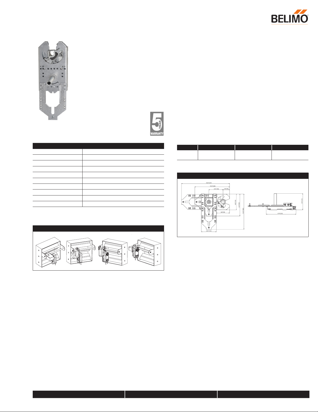
Application
The ZG-JSL jackshaft linkage is designed to easily attach to any part of a
jackshaft and allow easy installation of select Belimo actuators. The unique open
ended design and clamp insert allows the ZG-JSL to be used with any jackshaft
from ½” to ¾” in diameter. Removal of the insert will allow the linkage to attach
to a maximum shaft diameter of 1.05”. Changing the antirotation plate will allow
various actuators to be mounted.
Operation
The ¾” diameter built-in steel shaft allows direct coupling to the Belimo series
actuators in the chart below. There is a torque reduction when using the ZG-JSL
linkage. Verify application requirements before use.
Default/Configuration
The ZG-JSL linkage can also be configured by moving the anti-rotation plate
90° for space saving applications. See mounting configurations below. The ZG-
JSLA will have a factory mounted actuator on the linkage in the vertical position
only.
Suitable Actuators
Non-Spring Spring Electronic Fail-Safe
ZG-JSL EFB(X), AFB(X),
NFB(X), LF
GMB(X), AMB(X),
NMB(X)
GKB(X), NKQB(X)
Dimensions (Inches [mm])
ZG-JSL, ZG-JSLA Jackshaft Retrofit Linkage
For Use with Belimo Rotary Actuators
800-543-9038 USA 866-805-7089 CANADA 203-791-8396 LATIN AMERICA / CARIBBEAN
Date created, 11/14/2016 - Subject to change. © Belimo Aircontrols (USA), Inc.

Technical Data 1486
Power Supply 24 VAC ± 20%, 50/60 Hz, 24 VDC ± 10%
Power Consumption Running 3.5 W
Power Consumption Holding 1.3 W
Transformer Sizing 6 VA (class 2 power source)
Shaft Diameter 1/2” to 1.05” round, centers on 1/2” and 3/4”
with insert, 1.05” without insert
Electrical Connection 18 GA plenum rated cable with 1/2” conduit
connector protected NEMA 2 (IP54) 3ft [1m]
10ft [3m] and 16ft [5m]
Overload Protection electronic throughout 0° to 95° rotation
Input Impedance 100 k Ωfor 2 to 10 VDC (0.1 mA), 500 Ωfor 4
to 20 mA, 1500 Ωfor PWM, floating point and
On/Off
Feedback Output U 2 to 10 VDC, 0.5 mA max, VDC variable
Angle of Rotation Max. 95°, adjustable with mechanical stop
Torque 180 in-lbs [20 Nm] minimum
Direction of Rotation (Motor) reversible with switch
Position Indication reflective visual indicator (snap on)
Manual Override external push button
Running Time (Motor) 150 sec (default), variable (90 to 350 sec)
Humidity 5 to 95% RH non condensing (EN 60730-1)
Ambient Temperature Range -22°F to 122°F [-30°C to 50°C]
Storage Temperature Range -40°F to 176°F [-40°C to 80°C]
Housing NEMA 2, IP54, UL enclosure type 2
Housing Material UL94-5VA
Agency Listings† cULus acc. to UL60730-1A/-2-14, CAN/CSA
E60730-1:02, CE acc. to 2004/108/EC and
2006/95/EC
Noise Level (Motor) <45 dB (A)
Servicing maintenance free
Quality Standard ISO 9001
Weight 2.6 lb [1.2 kg]
†Rated Impulse Voltage 800V, Type action 1, Control Pollution Degree 3.
Torque min. 180 in-lb, for control of damper surfaces up to 45 sq. ft.
Application
For proportional modulation of dampers in HVAC systems. Actuator sizing
should be done in accordance with the damper manufacturer’s specifications.
The actuator is mounted directly to a damper shaft up to 1.05” in diameter by
means of its universal clamp. A crank arm and several mounting brackets are
available for applications where the actuator cannot be direct coupled to the
damper shaft.
The default parameters for 2 to 10 VDC applications of the …MFT actuator are
assigned during manufacturing. If necessary, custom versions of the actuators
can be ordered. The parameters can be changed by two means: pre-set and
custom configurations from Belimo or on-site configurations using the Belimo
PC-Tool software.
Operation
The actuator is not provided with and does not require any limit switches, but is
electronically protected against overload. The anti-rotation strap supplied with
the actuator will prevent lateral movement.
The actuator provides 95° of rotation and a visual indicator indicates position of
the actuator. When reaching the damper or actuator end position, the actuator
automatically stops. The gears can be manually disengaged with a button on
the actuator cover.
The actuators use a brushless DC motor, which is controlled by an Application
Specific Integrated Circuit (ASIC). The ASIC monitors and controls the
actuator’s rotation and provides a digital rotation sensing (DRS) function to
prevent damage to the actuator in a stall condition. Power consumption is
reduced in holding mode.
Add-on auxiliary switches or feedback potentiometers are easily fastened
directly onto the actuator body for signaling and switching functions.
Dimensions (Inches[mm])
1.18" [30]
4.3" [109]
4.06" [103]
5.2" [131]
8.3" [211]
3.46" [88] 2.49" [63.4]
2" [50.8]
1/2” t o 1.05” [12.7 to 26.67]
2/5” t o 1.05” [10 to 26.67]
AMX24-MFT
Modulating, Non-Spring Return, 24 V, Multi-Function Technology®
800-543-9038 USA 866-805-7089 CANADA 203-791-8396 LATIN AMERICA / CARIBBEAN
Date created, 02/10/2017 - Subject to change. © Belimo Aircontrols (USA), Inc.

Typical Specification
Modulating control damper actuators shall be electronic direct coupled type,
which require no crank arm and linkage and be capable of direct mounting
to a shaft up to 1.05” diameter. Actuators must provide modulating damper
control in response to a 2 to 10 VDC or, with the addition of a 500 Ωresistor,
a 4 to 20 mA control input from an electronic controller or positioner.
Actuators shall have brushless DC motor technology and be protected from
overload at all angles of rotation. Actuators shall have reversing switch and
manual override on the cover. Run time shall be constant and independent
of torque. Actuators shall be cULus listed, have a 5-year warranty, and
be manufactured under ISO 9001 International Quality Control Standards.
Actuators shall be as manufactured by Belimo.
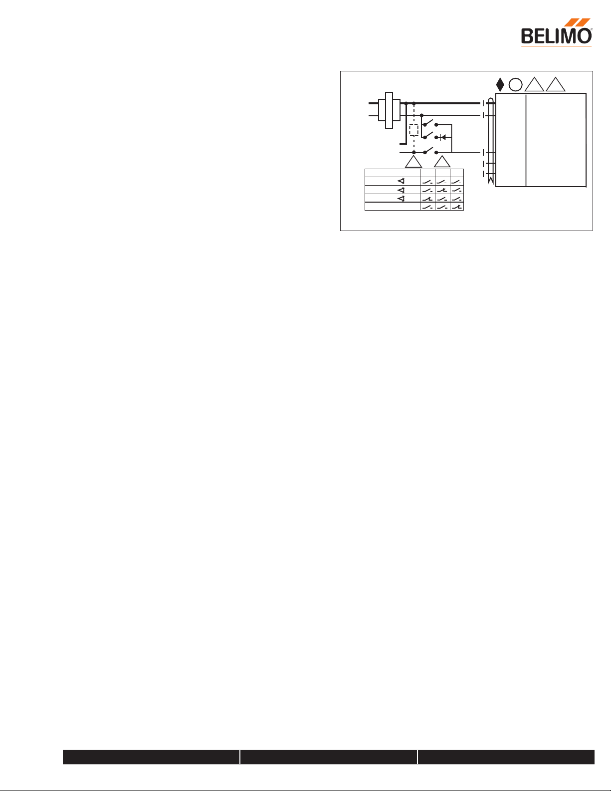
Wiring Diagrams
A
Actuators with appliance cables are numbered.
Provide overload protection and disconnect as required.
Actuators may also be powered by 24 VDC.
Only connect common to negative (-) leg of control circuits.
A 500 Ωresistor (ZG-R01) converts the 4 to 20 mA control signal to 2
to 10 VDC.
Control signal may be pulsed from either the Hot (Source) or Common
(Sink) 24 VAC line.
For triac sink the Common connection from the actuator must be
connected to the Hot connection of the controller. Position feedback
cannot be used with a triac sink controller; the actuator internal
common reference is not compatible.
Actuators may be connected in parallel if not mechanically linked. Power
consumption and input impedance must be observed.
IN4004 or IN4007 diode. (IN4007 supplied, Belimo part number
40155).
Blk (1)
Red (2)
Pnk (4)
Wht (3)
Org (5)
Line
Volts
Position
Feedback VDC
(+)
(–)
1 3 11
Common
Hot +
Y
2
Input
Y
1
Input
U Output
24 VAC Transformer
On/Off
Line
Volts
(–)
(+)
Position
Feedback VD
C
11110
Blk (1)
Red (2)
Pnk (4)
Wht (3)
Org (5)
Common
Hot +
Y
2
Input
Y
1
Input
U Output
24 VAC Transformer (AC Only)
Floating Point
(–)
(+)
Line
V
olts
Ω
500
Ω
1/4 watt
Control Signal
VDC / mA
1 3 511
7
Blk (1)
Red (2)
Pnk (4)
Wht (3)
Org (5)
Common
Hot +
Y
2
Input
Y
1
Input
U Output
24 VAC Transformer
VDC/mA Control
Line
Volt
s
(–)
(+)
Position
Feedback VDC
111
8
Blk (1)
Red (2)
Pnk (4)
Wht (3)
Org (5)
Common
Hot +
Y2Input
Y1Input
U Output
24 VAC Transformer (AC Only)
PWM Control
AMX24-MFT
Modulating, Non-Spring Return, 24 V, Multi-Function Technology®
800-543-9038 USA 866-805-7089 CANADA 203-791-8396 LATIN AMERICA / CARIBBEAN
Date created, 02/10/2017 - Subject to change. © Belimo Aircontrols (USA), Inc.
Functions
0%
50%
100%
Control mode acc. to Y
1
Min
Mid
Max
Normal
abcOrg (5)
24 VAC Transformer (AC Only)
U Output
A
1 5
Blk (1) Common
Red (2) + Hot
Pnk (4)
Wht (3)
(–)
(+)
Line
Volts
B
C
A
VDC / mA
Control Signal
Y2Input
Y1Input
12
7
Ω
Override Control
AMX24-MFT
Modulating, Non-Spring Return, 24 V, Multi-Function Technology®
800-543-9038 USA 866-805-7089 CANADA 203-791-8396 LATIN AMERICA / CARIBBEAN
Date created, 02/10/2017 - Subject to change. © Belimo Aircontrols (USA), Inc.
This manual suits for next models
2
Other Belimo Industrial Equipment manuals


