manuals.online logo
Brands
  1. Home
  2. •
  3. Brands
  4. •
  5. Victaulic
  6. •
  7. Industrial Equipment
  8. •
  9. Victaulic 746-LPA Series Setup guide

Victaulic 746-LPA Series Setup guide

SECTION VIEW DRAWING AND DESCRIPTION –
SERIES 746-LPA DRY ACCELERATOR
The Series 746-LPA Dry Accelerator is a quick-opening device, which
exhausts air from Series 767/776/798 Actuators to speed valve
operation.
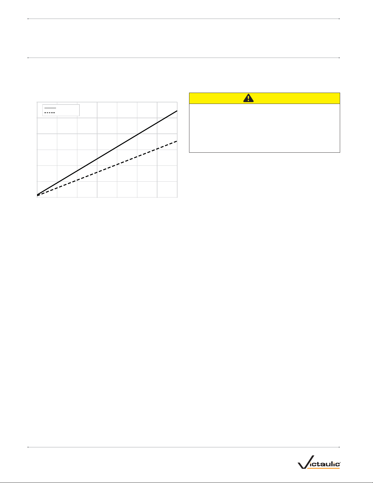
A diaphragm separates the Series 746-LPA Dry Accelerator into two
chambers. The closing chamber contains a compression spring, which
maintains the chamber in the closed position. The closed position is
maintained as long as the pressure differential between the opening and
closing chambers is less than 3 psi/21kPa.
When the system introduces air pressure into the dry accelerator, air
enters the closing chamber and passes through a check valve to the
opening chamber. The check valve, which allows flow into the open-
ing chamber, prevents pressure from escaping the opening chamber.
Therefore, air can escape only through the restrictor.
When a rapid loss of system air pressure occurs, such as an open
sprinkler, air escapes from the closing chamber faster than it escapes
from the opening chamber. As the sprinkler system’s pressure continues
to decay, a differential pressure develops across the diaphragm. When
this differential pressure reaches 3 – 5 psi/21 – 34 kPa, the opening
chamber’s pressure overcomes the compression spring’s closing force,
causing the closing chamber to open to the atmosphere. The closing
chamber opens immediately and releases pressure from the actuator,
resulting in valve operation.
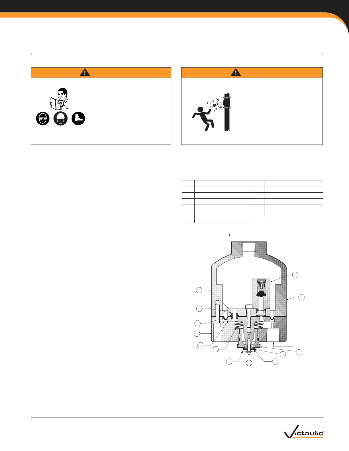
BILL OF MATERIALS
1 Opening/Air Chamber 8 Seal Support
2 Piston 9 Button-Head Cap Screw
3Restrictor 10ClosingChamberSeal
4Diaphragm 11Washer
5 Closing Chamber 12 Adjustable Seat
6 Actuator Shaft 13 Check Valve
7 Compression Spring
To Pressure
Gauge
Air Inlet
13
1
12
11
10
9
7
6
5
8
3
2
4
CROSS SECTION WITH UPPER CHAMBER ROTATED
45° AND BOLT REMOVED FOR CLARITY
Exaggerated for clarity
IMPORTANT INFORMATION
WARNING WARNING
Read and understand all instruc-
tions before attempting to perform
maintenance on any Victaulic
piping products.
Wear safety glasses, hardhat, and
foot protection.
Failure to follow these instructions
could result in serious personal
injury, property damage, and/or
product failure.
•
•
Depressurize and drain the piping
system before attempting to
remove, adjust, or perform main-
tenance on any Victaulic piping
products.
Failure to follow this instruction
could result in serious personal injury
and/or property damage.
•
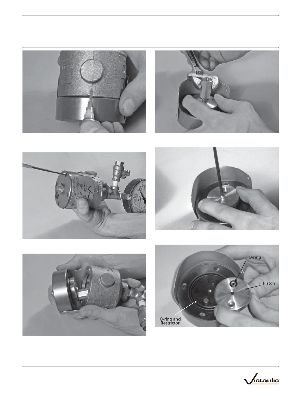
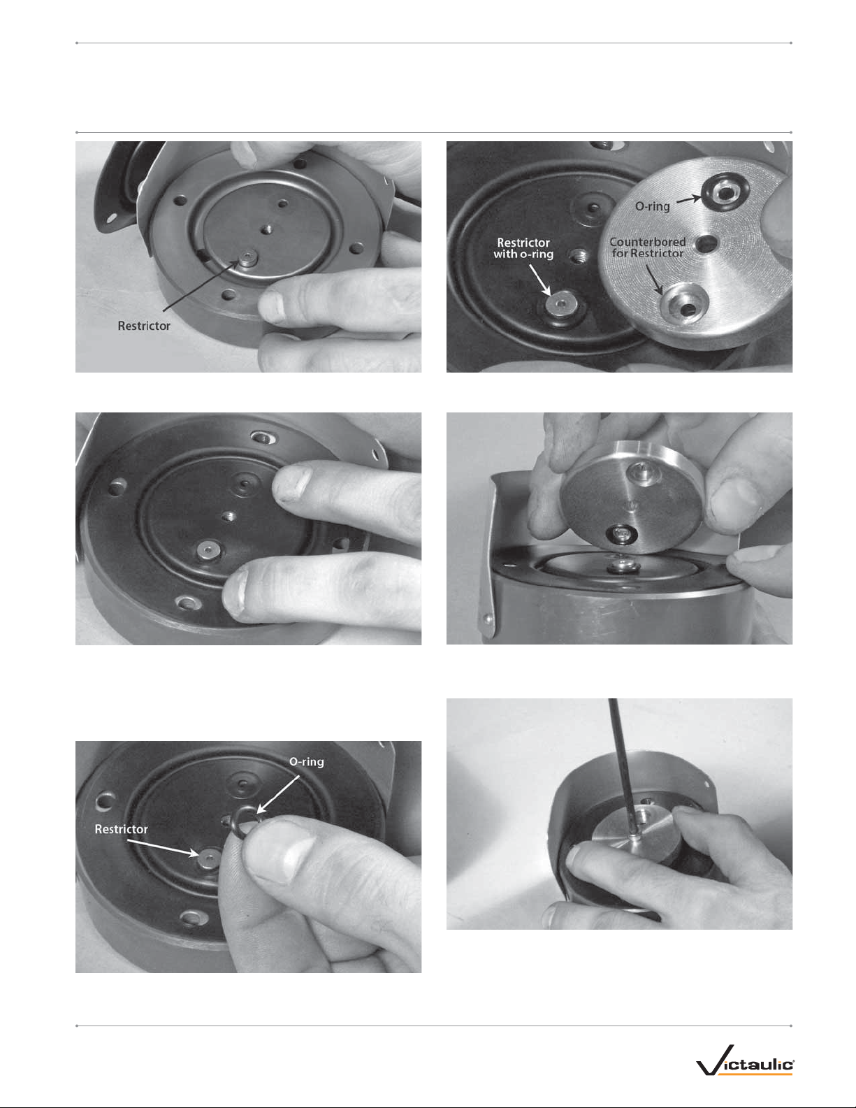
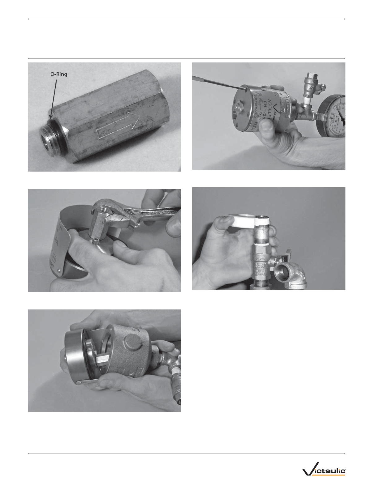
The following information is a guide for proper installation of Victaulic Series 746-LPA Dry Accelerators. Always refer to the installation,
maintenance, and testing manual for the applicable valve for detailed system setup, operation, and maintenance instructions.
I-746.LPA_1
Series 746-LPA
INSTRUCTIONS FOR INSTALLING AND REPAIRING SERIES 746-LPA DRY ACCELERATORS
I-746.LPAINSTALLATION AND REPAIR KIT INSTRUCTIONS
www.victaulic.com
VICTAULIC IS A REGISTERED TRADEMARK OF VICTAULIC COMPANY. © 2006 VICTAULIC COMPANY. ALL RIGHTS RESERVED. PRINTED IN THE USA.
REV_A
AIR SUPPLY REQUIREMENTS
Systems with air pressure higher than 18psi/124 kPa require the
addition of a Series 746-LPA Dry Accelerator.
COMPRESSOR REQUIREMENTS AND SETTINGS FOR SYSTEMS
INSTALLED WITH SERIES 746-LPA DRY ACCELERATORS
0
2
4
6
8
10
12
System Capacity (in gallons)
Required Flow Rate (CFM)
550
300
50
800
1050
1300
1550
1800
20 psi/138 kPa
13 psi/90 kPa
In the event a compressor becomes inoperative, a properly sized tank-
mounted air compressor provides the greatest protection for systems
installed with a Series 746-LPA Dry Accelerator. In this situation, air can
be supplied continuously to the sprinkler system for an extended time
period. NOTE: The Series 757 Regulated AMTA should be used with a
tank-mounted air compressor to supply air to a system when the Series
746-LPA Dry Accelerator is used. The use of an air regulator with a
base or riser-mounted compressor could cause short cycling, resulting
in premature wear of the compressor.
Set the air regulator of the Series 757 Regulated Air Maintenance Trim
Assembly (AMTA) to a minimum of 13psi/90 kPa.
The air regulator of the Series 757 Regulated AMTA is a relief-type
design. Any pressure in the system that is above the set point of the air
regulator will be released. Therefore, charging the air regulator above
the set point could cause premature operation of a system installed with
a Series 746-LPA Dry Accelerator.
THE SERIES 757P AIR MAINTENANCE TRIM ASSEMBLY WITH
PRESSURE SWITCH MUST NOT BE USED ON A SYSTEM
INSTALLED WITH A SERIES 746-LPA DRY ACCELERATOR.
INSTALLATION
For proper operation and approval, the valve and any accessories must
be installed in accordance with the specific trim diagrams included with
the shipment.
CAUTION
Make sure no foreign material gets into the pipe nipples and
openings in the accelerator.
If using any material other than Teflon* tape, use extra
caution so that no material gets into the trim.
Failure to follow these instructions could cause improper valve
operation, resulting in personal injury and/or property damage.
•
•
1. Apply a small amount of pipe joint compound or Teflon* tape to
the external threads of all threaded pipe connections. DO NOT get
any tape, compound, or other foreign material into the pipe nipples
and openings in the accelerator.
2. Assemble the Series 746-LPA Dry Accelerator per the drawing
provided.
3. Install the Series 746-LPA Dry Accelerator into the trim of the
actuator in the location designated on the applicable trim draw-
ing. Make sure the end of the Series 746-LPA with the vent seal
“button” is facing toward the trim of the actuator.
PLACING THE SYSTEM IN SERVICE
When the system is ready to be placed in service, refer to the instal-
lation, maintenance, and testing manual for the applicable valve for
detailed setup instructions.
*TEFLON IS A REGISTERED TRADEMARK OF THE DUPONT COMPANY.
I-746.LPA_2
Series 746-LPA
INSTRUCTIONS FOR INSTALLING AND REPAIRING SERIES 746-LPA DRY ACCELERATORS
I-746.LPAINSTALLATION AND REPAIR KIT INSTRUCTIONS
www.victaulic.com
VICTAULIC IS A REGISTERED TRADEMARK OF VICTAULIC COMPANY. © 2006 VICTAULIC COMPANY. ALL RIGHTS RESERVED. PRINTED IN THE USA.
REV_A
REPAIR KIT INSTRUCTIONS
CAUTION
Any activities that require taking the
valve out of service may eliminate the fire
protection provided.
Before servicing or testing the system, notify
the authority having jurisdiction.
Consideration of a fire patrol should be given
in the affected areas.
Failure to follow these instructions could result
in serious personal injury and/or property
damage.
•
•
•
CAUTION
The isolation ball valve MUST remain closed during the follow-
ing procedures.
Failure to follow this instruction could cause the valve to false
trip, resulting in property damage.
•
CONTENTS OF REPAIR KIT
Item Qty. Description
11Diaphragm
2 1 Check Valve with O-Ring
31Restrictor
42O-Ring
1. Close the isolation ball valve of the Series 746-LPA Dry
Accelerator.
2. Open the ¼-turn vent ball valve of the Series 746-LPA Dry
Accelerator. Confirm that the gauge on the accelerator reads
0 psi/0 Bar.
3. Remove the Series 746-LPA from the nipple above the isolation
ball valve, as shown.
I-746.LPA_3
Series 746-LPA
INSTRUCTIONS FOR INSTALLING AND REPAIRING SERIES 746-LPA DRY ACCELERATORS
I-746.LPAINSTALLATION AND REPAIR KIT INSTRUCTIONS
www.victaulic.com
VICTAULIC IS A REGISTERED TRADEMARK OF VICTAULIC COMPANY. © 2006 VICTAULIC COMPANY. ALL RIGHTS RESERVED. PRINTED IN THE USA.
REV_A
4. Using a marker, place a mark on the upper and lower housings.
This mark will aid in aligning the upper and lower housings during
re-assembly.
5. Using a ⁄-inch hex wrench, remove the four cap screws from the
lower housing. Keep these cap screws for re-installation.
6. Separate the lower housing from the upper housing.
7. Using an adjustable wrench, remove and discard the check valve
and o-ring.
8. Using a ⁄-inch hex wrench, remove the cap screw that retains
the piston. Keep this cap screw for re-installation.
9. Remove the piston, the two o-rings, the restrictor, and the
diaphragm. Keep the piston for re-assembly. Discard the restrictor,
diaphragm, and two o-rings.
10. Remove any debris from the sealing areas of the lower housing
with a soft rag and non-abrasive cleaner.
I-746.LPA_4
Series 746-LPA
INSTRUCTIONS FOR INSTALLING AND REPAIRING SERIES 746-LPA DRY ACCELERATORS
I-746.LPAINSTALLATION AND REPAIR KIT INSTRUCTIONS
www.victaulic.com
VICTAULIC IS A REGISTERED TRADEMARK OF VICTAULIC COMPANY. © 2006 VICTAULIC COMPANY. ALL RIGHTS RESERVED. PRINTED IN THE USA.
REV_A
11. Insert the NEW restrictor, provided with the kit, into the lower
housing, as shown above.
12. Install the NEW diaphragm, provided with the kit, onto the lower
housing. Make sure the raised portion of the diaphragm is installed
toward the lower housing and that it engages with the recess.
Position the diaphragm so that the largest hole in the center por-
tion of the diaphragm aligns with the recess where the restrictor is
installed, as shown above.
13. Install a NEW o-ring, provided with the kit, around the restrictor.
14. Install a NEW o-ring, provided with the kit, into the recess in the
piston that IS NOT counterbored, as shown above.
15. Align the recesses in the piston with the holes in the diaphragm.
NOTE: The counterbore of the piston must align with the restrictor,
as shown above.
16. Insert the cap screw into the piston assembly. Using a ⁄-inch hex
wrench, fully tighten the cap screw.
I-746.LPA_5
Series 746-LPA
INSTRUCTIONS FOR INSTALLING AND REPAIRING SERIES 746-LPA DRY ACCELERATORS
I-746.LPAINSTALLATION AND REPAIR KIT INSTRUCTIONS
www.victaulic.com
VICTAULIC IS A REGISTERED TRADEMARK OF VICTAULIC COMPANY. © 2006 VICTAULIC COMPANY. ALL RIGHTS RESERVED. PRINTED IN THE USA.
REV_A
17. Make sure a NEW o-ring is installed on the NEW check valve, as
shown above.
18. Using an adjustable wrench, install the NEW check valve into the
piston, as shown above.
19. Align the bolt holes of the upper and lower housings. NOTE: Since
one set of bolt holes is offset, use the marks made in step 4 to aid
in alignment.
20. Insert a cap screw into each of the four holes. Using a ⁄-inch hex
wrench, fully tighten the four cap screws.
21. Re-apply a small amount of pipe joint compound or Teflon* tape
to the nipple above the isolation ball valve. DO NOT get any tape,
compound, or other foreign material into the nipple or openings in
the accelerator.
*TEFLON IS A REGISTERED TRADEMARK OF THE DUPONT COMPANY.
I-746.LPA_6
Series 746-LPA
INSTRUCTIONS FOR INSTALLING AND REPAIRING SERIES 746-LPA DRY ACCELERATORS
I-746.LPAINSTALLATION AND REPAIR KIT INSTRUCTIONS
www.victaulic.com
VICTAULIC IS A REGISTERED TRADEMARK OF VICTAULIC COMPANY. © 2006 VICTAULIC COMPANY. ALL RIGHTS RESERVED. PRINTED IN THE USA.
REV_A
22. Install the repaired Series 746-LPA Dry Accelerator assembly onto
the nipple above the isolation ball valve.
23. Close the ¼-turn vent ball valve of the Series 746-LPA Dry
Accelerator.
24. Open the isolation ball valve of the Series 746-LPA Dry
Accelerator. This will set the accelerator.
25. Observe the system air pressure over a 24-hour period to confirm
system integrity. If there is degradation in system air pressure, find
and correct all leaks. NOTE: NFPA requires less than 2-psi/14-kPa
leakage in 24 hours.
26. Notify the authority having jurisdiction that the valve has been
placed back in service.
I-746.LPA_7
Series 746-LPA
INSTRUCTIONS FOR INSTALLING AND REPAIRING SERIES 746-LPA DRY ACCELERATORS
I-746.LPAINSTALLATION AND REPAIR KIT INSTRUCTIONS
www.victaulic.com
VICTAULIC IS A REGISTERED TRADEMARK OF VICTAULIC COMPANY. © 2006 VICTAULIC COMPANY. ALL RIGHTS RESERVED. PRINTED IN THE USA.
REV_A
TROUBLESHOOTING – SERIES 746-LPA DRY ACCELERATOR
PROBLEM POSSIBLE CAUSE SOLUTION
The valve operates without sprinkler activation. There is a loss of air pressure in the lower inlet chamber of the Series
746-LPA Dry Accelerator.
Check for air loss at the lower chamber seal. If a leak is present, turn
the adjustment nut counterclockwise to seal.
Check for any leaks in the system and trim. Conrm that the air
maintenance trim assembly (AMTA) is operating properly.
The Series 746-LPA Dry Accelerator does not operate within a
5-psi/34-kPa pressure drop in system air pressure.
There is a loss of air pressure in the upper air chamber of the Series
746-LPA Dry Accelerator.
Apply soapy water to all joints around the Series 746-LPA Dry
Accelerator to check for leaks. Repair any leaks and re-test.
The air decay rate of the system is too slow. Make sure there are no restrictions in the remote system test valve
(inspector’s test connection).
If the above procedures do not work, contact Victaulic.
The Series 746-LPA Dry Accelerator does not set up properly
(cannot get pressure on the upper gauge, and the button pops up
immediately when pressure is introduced).
The Series 746-LPA Dry Accelerator is installed upside-down. Remove the Series 746-LPA Dry Accelerator from the trim, and
turn the unit around so that the vent seal“button”is facing down
(toward the actuator).
WCAS-6TMG37
I-746.LPA
Series 746-LPA
INSTRUCTIONS FOR INSTALLING AND REPAIRING SERIES 746-LPA DRY ACCELERATORS
I-746.LPAINSTALLATION AND REPAIR KIT INSTRUCTIONS
UPDATED 10/2006
I-746.LPA 4603 REV A Z000746LPA
VICTAULIC IS A REGISTERED TRADEMARK OF VICTAULIC COMPANY. © 2006 VICTAULIC COMPANY. ALL RIGHTS RESERVED. PRINTED IN THE USA.
US & WORLD HEADQUARTERS
P. O . B o x 3 1
Easton, PA 18044-0031 USA
4901 Kesslersville Road
Easton, PA 18040 USA
1-800-PICK-VIC (1-800-742-5842)
1-610-559-3300
1-610-250-8817 (fax)
pickvic@victaulic.com
CANADA
905-884-7444
905-884-9774 (fax)
viccanada@victaulic.com
EUROPE
32-9-381-15-00
32-9-380-44-38 (fax)
viceuro@victaulic.be
UNITED KINGDOM
44 (0) 1438741100
44 (0) 1438313883 (fax)
viceuro@victaulic.be
CENTRAL AND SOUTH AMERICA
1-610-559-3300
1-610-559-3608 (fax)
vical@victaulic.com
ASIA PACIFIC
86-21-54253300
86-21-54253671 (fax)
vicap@victaulic.com
MIDDLE EAST
971-4-883-88-70
971-4-883-88-60 (fax)
www.victaulic.com

Other Victaulic Industrial Equipment manuals

Victaulic VicFlex I-VICFLEX User manual

Victaulic

Victaulic VicFlex I-VICFLEX User manual

Victaulic VE414 Manual

Victaulic

Victaulic VE414 Manual

Victaulic UM Series User manual

Victaulic

Victaulic UM Series User manual

Victaulic VE460 Manual

Victaulic

Victaulic VE460 Manual

Popular Industrial Equipment manuals by other brands

Transfer Oil GOMAX QUADRA DN2 Assembling instructions

Transfer Oil

Transfer Oil GOMAX QUADRA DN2 Assembling instructions

Nordco TRIPP HD Operation manual

Nordco

Nordco TRIPP HD Operation manual

Watts FGD Series installation manual

Watts

Watts FGD Series installation manual

TMG TMG-PD700S product manual

TMG

TMG TMG-PD700S product manual

Titan 305 Installation, maintenance & parts manual

Titan

Titan 305 Installation, maintenance & parts manual

Eagle T10CF Operation manual

Eagle

Eagle T10CF Operation manual

VS DATAGAUSS LG operating manual

VS

VS DATAGAUSS LG operating manual

Watts LFC500-FS Series Installation maintenance repair manual

Watts

Watts LFC500-FS Series Installation maintenance repair manual

Afag LF9 Operating & installation instructions

Afag

Afag LF9 Operating & installation instructions

TMG TMG-RSV70G product manual

TMG

TMG TMG-RSV70G product manual

Radijator TKAN Integra Series instruction manual

Radijator

Radijator TKAN Integra Series instruction manual

CIAT DynaCIAT LG instruction manual

CIAT

CIAT DynaCIAT LG instruction manual

Sonny's Arcade Arch owner's manual

Sonny's

Sonny's Arcade Arch owner's manual

Epiroc FORDIA Casing Advancer Standard Operator's manual

Epiroc

Epiroc FORDIA Casing Advancer Standard Operator's manual

Jäger Z62-K360.12 S5IP manual

Jäger

Jäger Z62-K360.12 S5IP manual

Eaton RS2 Series Instruction leaflet

Eaton

Eaton RS2 Series Instruction leaflet

schmersal AZM201Z-SK-T-SD2P manual

schmersal

schmersal AZM201Z-SK-T-SD2P manual

Vega M-BUS-2 user manual

Vega

Vega M-BUS-2 user manual

manuals.online logo
manuals.online logoBrands
  • About & Mission
  • Contact us
  • Privacy Policy
  • Terms and Conditions

Copyright 2025 Manuals.Online. All Rights Reserved.