Bell and Gossett CRS Series User manual
Bell & Gossett ®
Instruction Manual V1000266
Series CRS
Coalescing Removal Separator
Installation, Operation and Service Instructions
INSTALLER: PLEASE LEAVE THIS MANUAL FOR THE OWNER’S USE.
WARNING: This product may contain chemicals known to the State of California to cause cancer, or birth
defects or other reproductive harm.
SAFETY INSTRUCTION: This safety alert symbol will be used in this manual to draw attention to safety related
instructions. When used, the safety alert symbol means ATTENTION! BECOME ALERT! YOUR SAFETY IS
INVOLVED! FAILURE TO FOLLOW THE INSTRUCTIONS MAY RESULT IN A SAFETY HAZARD.
Safety Message Level
DANGER:
WARNING:
CAUTION:
ELECTRICAL HAZARD:
NOTICE:
Indication
A hazardous situation, which if not avoided, will result in death or serious injury.
A hazardous situation, which if not avoided, will result in death or serious injury.
A hazardous situation, which if not avoided, will result in major or minor injury.
The possibility of electrical risks if instructions are not followed in a proper
manor.
• A hazardous situation, which if not avoided, will result in an indescribable
result or state.
• A practice not related to personal injury.
Project: Bentonville Jr High #4
Contractor: Comfort Systems USA
Representative: Boone & Boone Sales
Description
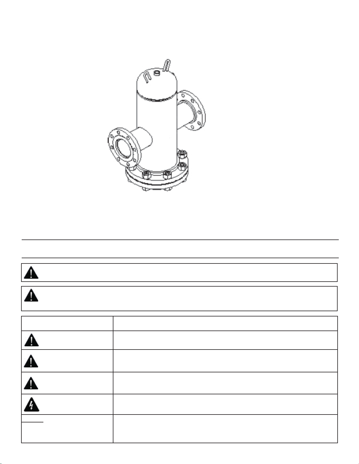
Bell & Gossett Series CRS Coalescing Removal Separators are designed to eliminate entrained air and separate debris
associated with start-up and maintenance of any hydronic system. The design incorporates an optional removable end
cover for coalescing medium access, and an optional air vent to automatically release air from the separator.
The design and construction conforms to ASME Section VIII, Div.1. This product is intended for hot and chilled water
systems.
Installation
A. PRE-INSTALLATION
1. Visually inspect Series CRS separator and check
for damage prior to installation.
Separator Temperature Max Working Pressure
CRS -20°F (-29°C) to 450°F (232°C) 125 PSI (862 kPa)
Operational Limits
WARNING: Explosion or Rupture Hazard. A relief valve must be installed to prevent pressure in excess of local
code requirement or maximum working pressure designated in the Product Manual, whichever is less. Do not
expose Series CRS Coalescing Removal Separator to freezing temperatures or temperatures in excess of 450°F.
Failure to properly size the Product or follow these instructions may result in excessive strain on the system
and may lead to Product failure, serious or fatal personal injury, leakage, and/or property damage.
WARNING: Read carefully the product installation, operating and maintenance instructions. Failure to follow
the instructions and warnings in the manual may result in serious or fatal injury and/or property damage, and
will void the product warranty. This product must be installed by a qualified professional. Follow all applicable
local and state codes and regulations, in the absence of such codes, follow the current editions of the National
Plumbing Code and National Electric Code, as applicable.
WARNING: : This product, like most products under pressure, may over time corrode, weaken and burst or
explode, causing serious or fatal personal injury, leaking or flooding and/or property damage. To minimize risk,
a licensed professional must install and periodically inspect and service the Product. A drip pan connected to
an adequate drain must be installed if leaking or flooding could cause property damage. Do not locate in an
area where leaking could cause property damage.
WARNING: If the separator is damaged,
it must be replaced. Failure to follow this
instruction may result in serious personal
injury or death and property
damage.
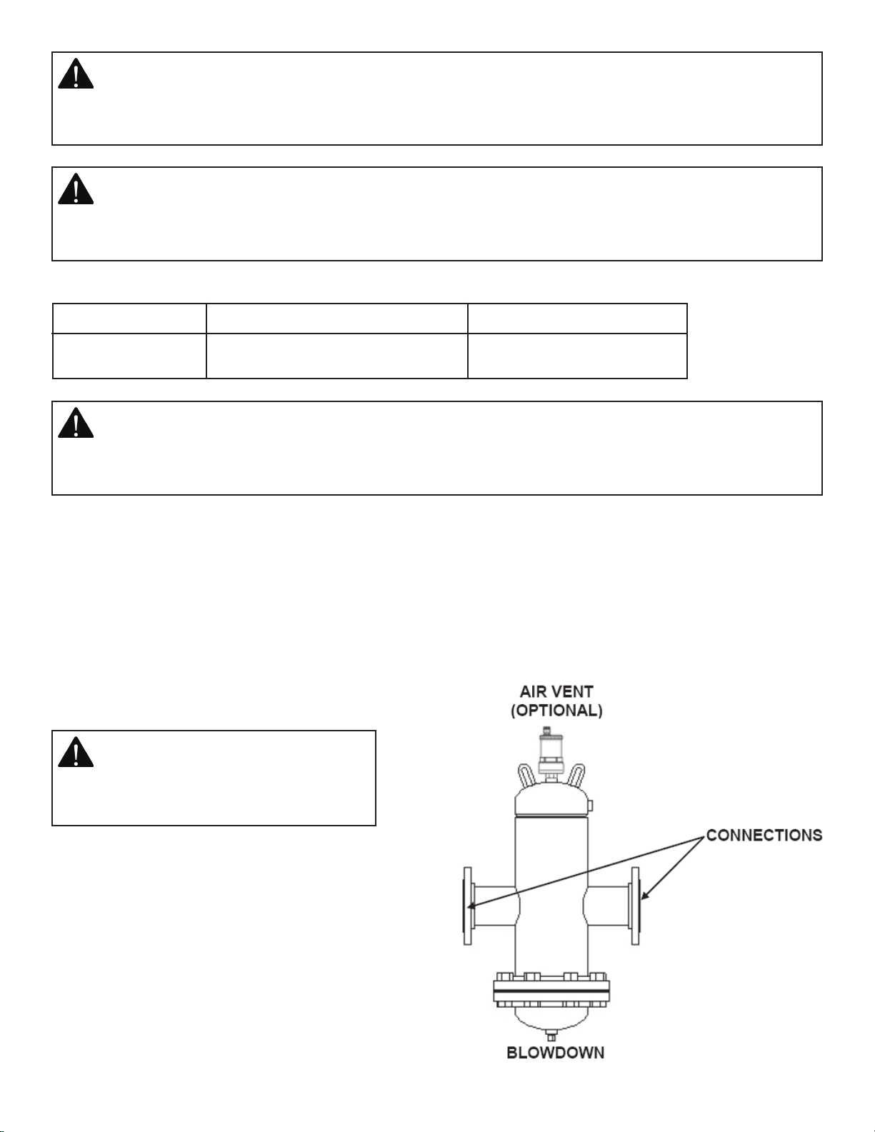
2. In order to protect the Series CRS separator
from shipping damage, some components are
shipped unattached and in a protective box. These
components are to be added to the Series CRS
separator on site. See Figure 1.
fig. 1

WARNING: System fluid under pressure and/or at high temperatures can be very hazardous. Before servicing,
reduce system pressure to zero or isolate the vessel from the system. Allow system to cool below 100°F and
above 35°F. Failure to follow this instruction may result in serious personal injury and/or property damage.
B. INSTALLATION
It should be noted that the solubility of air into water decreases as pressure drops and/or as temperature rises. Placing
the Bell & Gossett Series CRS separator before the pump inlet will also help pump performance and increase seal life.
CAUTION: Installation and maintenance must be performed by a qualified professional. Service should not
be performed on any component in an active hydronic loop. Before attempting to make any required adjust-
ments, properly isolate and drain the branch loops that require service and allow the valves to reach a safe
handling temperature and zero pressure condition. Use proper safety equipment including gloves, goggles,
or similar tools to avoid contact with system fluids and common hazards. Failure to follow these instructions
could result in personal injury and property damage.
The separator must be installed vertically.
Do not install on a dead end pipe or in an overhead joist space.
fig. 2 - Air Elimination
Figure 2 shows suggested mounting locations for a heating or cooling system.

WARNING: RUPTURE OR EXPLOSION HAZARD - Like most pressurized tanks, this tank can over time corrode,
weaken, and burst or explode. Failure to follow this instruction may result in serious personal injury or death
and property damage.
WARNING: CHLORINE & AGGRESSIVE WATER HAZARD - The water quality can significantly influence the life of
your product. You should test for corrosive elements, acidity, total solids, and other relevant contaminants, in-
cluding chlorine and treat your water appropriately to insure satisfactory performance and prevent premature
failure. Failure to follow this instruction may result in serious personal injury or death and property damage.
Before filling and starting the operation of a HVAC system, a properly applied and sized pressure relief valve must be
installed and in good operating order.
During filling and start-up after servicing, the system pressure should be closely monitored to ensure the pressure does
not exceed the pressure relief valve rating.
Consult the applicable pressure relief valve manufacturer’s instructions as necessary.
System Venting and Purging
After initial venting and purging of air from the system, more air will be released from the water as it is heated. An
optional Bell & Gossett No. 98 Air Vent may be assembled at the top of the Series CRS separator.
If the system has multiple loops or zones, the supply water for all loops and zones must pass through the Series CRS
separator for complete and continuous air removal. In case the piping arrangement does not permit the installation of
a single separator on the main, additional separators should be installed on each loop or zone. In this event, only one
expansion tank is required for the system.
Even with a No. 98 air vent installed on the separator, it is recommended that additional Bell & Gossett air vents be
installed on high points in the system.
CAUTION: Uncontrolled venting of water can occur with automatic air vents if foreign material prevents vent
from closing. Unwanted flow should be directed to a drain. Failure to follow these instructions could result in
property damage and/or moderate personal injury.
NOTICE: Never use the separator itself as a form of piping support. Please support separator and piping ac-
cording to the local building code. Failure to follow these instructions may result in property damage.
A manual blow down valve can be added to the blow down connection at the bottom of the separator. The function of
the blow down valve is to facilitate the purging of sediment from the vessel.
CAUTION: Use unit lifting lugs only to lift unit as shipped from factory. Unit must be empty and disconnected
from pipe, and other restraints. Use proper rigging procedures. Failure to follow these instructions could result
in injury or property damage.
Be aware of water weight in the separator and connected piping when installing your system. The wet filled weight of
the Series CRS separators can exceed the strength of the supports used. Make sure that provisions are made to properly
support the wet filled separator.
Welding to the pressure vessel boundary will void the ASME stamp.
Upon initial start up, the blow down valve should be operated frequently. At each blow down operation, document the
amount of sediment collected and the amount of time since the previous blow down operation. Use this information to
determine and adequate blow down schedule for your system.
The selection, application, installation and servicing of this product should be performed by a qualified professional
within all applicable safety and code requirements.
Service Instructions
Check the Series CRS separator periodically for signs of external leakage or corrosion. If any is found, the separator
must be replaced.
WARNING: Signs of leakage or corrosion are indications the Series CRS separator may have failed. Periodically
check the expansion tank for signs of external leakage or corrosion. If found, the tank must be replaced.
Failure to follow these instructions may result in serious personal injury or death and property damage.
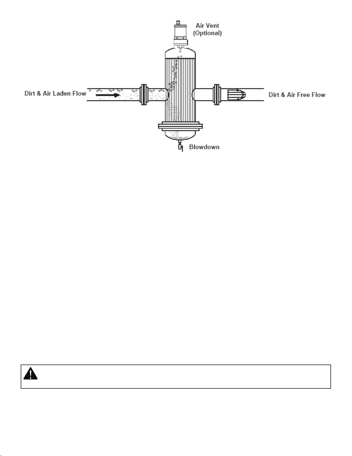
1. The system water contains air bubbles, entrained air, and dirt particles.
2. Large air bubbles quickly rise to the top of the vessel and into the vent. Micro-bubbles coalesce and form larger
bubbles. Entrained air is pulled out of solution and forms micro bubbles.
3. The air vent releases air fast as it can be separated.
4. Dirt particles are strained or filtered from the water and collect in the bottom of the vessel.
5. The coalescing medium/filter separates the air and dirt from the water. Stainless steel construction provides durability
and long life.
6. Should the need to clean the coalescing medium arise, the standard removable bottom cover provides ease of
removal and cleaning.
7. Collected sediment can be flushed out through the blow down valve.
fig. 3 - Series CRS Operation
Operating Instructions

fig. 4
2. Open the blow down valve for a few seconds. This should dislodge accumulated dirt or sediment from the medium.
If it does not, then the coalescing medium must be removed from the Series CRS separator for cleaning. This can be
accomplished by closing the isolation valves to isolate the separator from the system. Make sure that the system water
was allowed to reach a safe handling temperature, and the separator to reach a zero pressure condition. Open the
blow down valve on the bottom of the separator to drain the unit. Make sure that all flow from the blow down valve
has stopped. If water continues to flow, the isolation valves must be repaired or replaced before proceeding.
3. For Series CRS separators with removable heads, remove the flange bolts that hold the coalescing medium housing
cover (head) in place on the bottom of the separator.
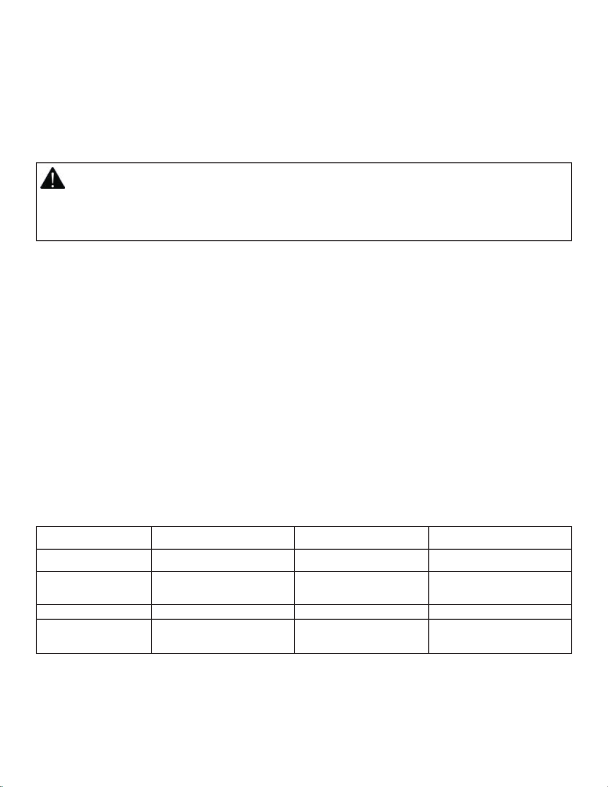
4. Clean the medium and reinstall in the Series CRS separator. Replace the cover head gasket with a new one and
reinstall the cover making sure that the flange bolts are tightened. The bolts should be torqued incrementally to 30%,
60%, and then to 100% of the appropriate value shown on the table on the next page. The bolts should be torqued in
the sequential order of the appropriate pattern shown in Figure 4.
WARNING: System fluid under pressure and/or at high temperatures can be very hazardous. Before servicing,
reduce system pressure to zero or isolate the vessel from the system. Allow system to cool below 100°F and
above 35°F. Failure to follow this instruction may result in serious personal injury and/or property damage.
The coalescing medium in the Series CRS separator may need to be cleaned periodically. This is true during the initial
start-up period. The need to clean the coalescing medium will be evidenced by a high pressure drop across the
separator or by pump cavitation problems. To clean the medium:
1. Allow the system water to reach a safe handling temperature
5. Once the cover has been reassembled to the Series CRS separator and the bolts have been appropriately tightened,
close the blowdown valve at the bottom of the separator and open the isolation valves to return the separator to
normal operation.
Service Instructions - Accessories
The Series CRS separator may have optional accessories assembled at the factory, or by the installer at the job site.
These components include a Bell & Gossett No. 98 Air Vent; a blowdown valve; or a skim valve. The factory installed
components come pre-assembled with a leading industrial thread sealant, Loctite 567, and are tightened to
appropriate levels. With that in mind, the following information should help to clarify questions regarding the
adjustment, servicing, or field installation of those components when required.
Any field adjustment of factory installed components will break the original thread seal and could cause leakage. This
will necessitate the removal, cleaning, and resealing of those parts per the instructions below.
Should any adjustment or servicing of air vents, blowdown valves, skim valves, drain plugs, or other accessories be
required, please take the following steps:
1. Completely remove the desired component from the Model CRS Separator.
2. Taking care not to damage any threads on the component or the separator, clean off all of the old thread sealant.
Use a wire brush and gentle abrasion if necessary. Allow the valve and the component to dry. Note: If the component
or valve appears to have been damaged, replace it.
3. Starting with the second thread of the NPT male component, apply a 360° bead of Loctite 567 thread
sealant/lubricant as shown below. Follow Loctite handling precautions as noted on the product labeling.
4. If Loctite 567 is unavailable, recommends RectorSeal No. 5 pipe thread sealant for all non-glycol based
applications, or any PTFE thread sealing tape. Be sure to follow the manufacturer specific handling precautions and
application instructions as noted on the product labeling.
5. Thread component into valve until it is finger tight.
6. Apply torque to the following specification:
CAUTION: Installation and maintenance must be performed by a qualified professional. Service should not
be performed on any valve in an active Hydronic loop. Before attempting to make any required adjustments,
properly isolate and drain the branch loops that require service and allow the valves to reach a safe handling
temperature and zero pressure condition. Use proper safety equipment including gloves, goggles, or similar
tools to avoid contact with system fluids and common hazards. Failure to follow these instructions could
result in personal injury and property damage.
Component Separator Size Connection Size Torque
Skim Valve 2” Through 12” 1/2” NPT 9.0 ft.-lbs + 3.0 ft.-lbs. / -0
Blowdown Valve 2” Through 6” 1/2” NPT 9.0 ft.-lbs + 3.0 ft.-lbs. / -0
8” Through 12” 1” NPT 12.0 ft.-lbs + 4.0 ft.-lbs. / -0
Air Vent 2” Through 12” 1/2” NPT 9.0 ft.-lbs + 3.0 ft.-lbs. / -0
Plug 2” Through 12” 1/2” NPT 9.0 ft.-lbs + 3.0 ft.-lbs. / -0
2” Through 12” 1” NPT 12.0 ft.-lbs + 4.0 ft.-lbs. / -0

Copyright © 2010
8200 N. Austin Ave.
Morton Grove, IL 60053
Tel: (847) 966-3700
Fax: (847) 966-9052
www.bellgossett.com
7. Properly assembled separator components will immediately seal to moderate pressure (100 PSI or less). For maximum
pressure resistance, allow the Loctite 567 or RectorSeal No. 5 thread sealant to cure for 24 hours. PTFE tape typically
does not require curing to achieve maximum pressure resistance.
Loctite and Loctite 567 are registered trademarks of Henkel AG & Co. RectorSeal No. 5 is a registered trademark of
RectorSeal Corporation.
NOTICE: Over application of torque may cause damage to the Separator or accessory component.
Table of contents
Other Bell and Gossett Water Filtration System manuals

Popular Water Filtration System manuals by other brands


Royal Doulton
Royal Doulton Elite installation instructions

Clean Water Systems
Clean Water Systems 7500 Series Installation & start?up guide

Hayward
Hayward AquaRite + owner's manual

BestWater
BestWater Jungbrunnen 66-10 user manual

MEDENUS
MEDENUS DF 100 Operating and maintenance instructions

BWT
BWT BWT bestaqua 24 HQ Fitting and operating instructions


