Smeg WO-20-01 User manual

7596056 –MANUALE WO-20-01 ENG_REV. 2
WO-20-01
Potable water treatment osmosis system for HO.RE.CA. applications.
MANUAL
Use e maintenance

7596056 –MANUALE WO-20-01 ENG_REV. 2
- 2 -
EU declaration of conformity
1. Equipment/Product Model
WO-20-01
Potable water treatment osmosis system for HO.RE.CA. applications.
2. Name and address of the manufacturer or his authorized representative:
SMEG SPA
Street L. Da Vinci, 4
42016 Guastalla (RE)
3. This declaration of conformity is issued under the sole responsibility of the manufacturer.
4. Aim of the declaration:
Production year 2018 and subsequent
5. The object of the declaration described above is in conformity with the relevant Union
harmonization legislation
- 2006/42/UE (MACHINES)
- 2014/30/UE (EMC)
- 2014/35/UE (LVD)
- 2015/863/UE (RHOS3)
6. References to the relevant harmonized standards used, including the date of the rules, or
reference to other technical specifications in relation to which conformity is declared,
including the date of the specifications:
•EN 62233:2008/AC:2010
•EN 55014-1:2006/A1:2009
•EN 55014-1:2006/A2:2011
•EN 55014-2:2015
•EN 61000-3-3:2013
•EN 60335-1:2012/AC:2014
•EN 60335-2-40:2003/A13:2012/AC:2013
22/05/2018
SMEG S.p.A.

7596056 –MANUALE WO-20-01 ENG_REV. 2
- 3 -
INDICE
1GENERAL INFORMATIONS.......................................................................................................................................- 5 -
1.1 MANUFACTURER / ASSISTANCE.......................................................................................... - 5 -
1.2 CERTIFICATION ............................................................................................................ - 5 -
1.3 PURPOSE OF THE MANUAL AND ITS CONTENTS........................................................................ - 5 -
1.4 CARE AND STORAGE OF THE MANUAL .................................................................................. - 5 -
1.5 IMPORTANT SYMBOLS TO REMEMBER ................................................................................... - 5 -
2CHARACTERISTICS OF THE DEVICE......................................................................................................................- 6 -
2.1 RECOMMENDED USE ....................................................................................................... - 6 -
2.2 FORBIDDEN USE............................................................................................................ - 6 -
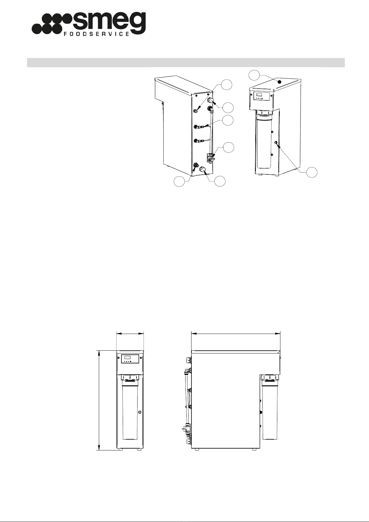
2.3 DESCRIPTION............................................................................................................... - 7 -
2.4 EXTERNAL DIMENSIONS ................................................................................................... - 7 -
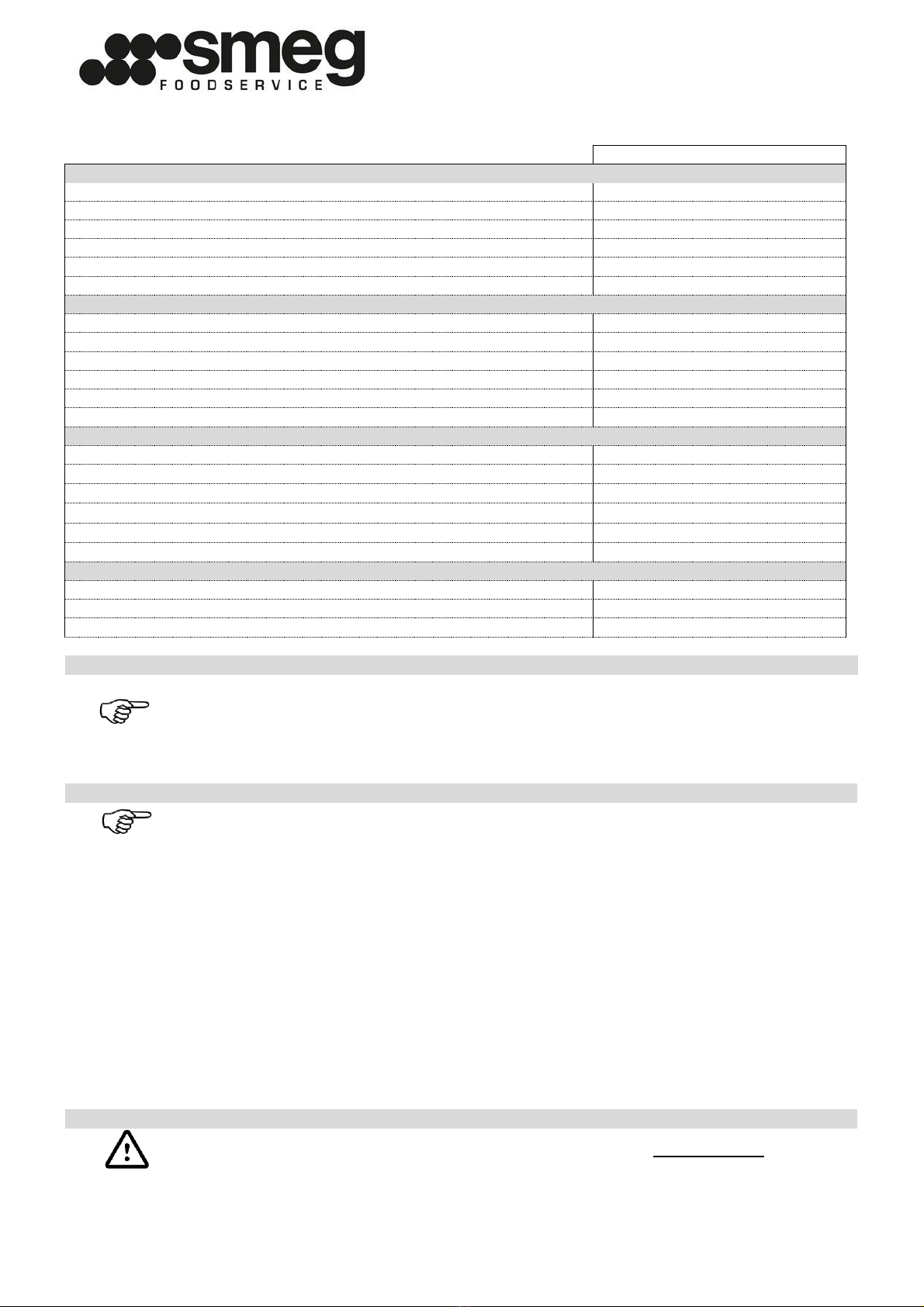
2.5 TECHNICAL SPECIFICATIONS ............................................................................................. - 8 -
3INSTALLATION ..........................................................................................................................................................- 9 -
3.1 EN1717 DRAIN ADAPTER INSTALLATION ................................................................................ - 9 -
3.2 EXCHANGE OF DRAIN CAPILLARY....................................................................................... - 10 -
4FUNCTIONING..........................................................................................................................................................- 12 -
4.1 FIRST START-UP .......................................................................................................... - 12 -
4.2 NORMAL USE .............................................................................................................. - 12 -
4.3 MIX - BY-PASS............................................................................................................. - 12 -
4.4 LOW PRESSURE ALARM .................................................................................................. - 12 -
4.5 LEACKAGE ALARM ........................................................................................................ - 12 -
4.6 HIGH CONDUCTIVITY ALARM............................................................................................ - 13 -
4.7 INACTIVITY ................................................................................................................ - 13 -
4.8 ELECTRONIC BOARD FUNCTIONING .................................................................................... - 14 -
4.9 CONFIGURATION MENU .................................................................................................. - 15 -
5ORDINARY MAINTENANCE TO BE DONE BY USER............................................................................................- 16 -
5.1 TASKS OF MAINTENANCE PERSONNEL.................................................................................. - 16 -
6EXTRAORDINARY MAINTENANCE TO BE DONE QUALIFIED PERSONNEL .....................................................- 17 -
6.1 TASKS OF MAINTENANCE PERSONNEL.................................................................................. - 17 -
6.2 PRE-FILTER REPLACEMENT .............................................................................................. - 18 -
6.3 PRECHARGE OF EXPANSION TANK...................................................................................... - 19 -
6.4 MACHINE SANITATION ................................................................................................... - 20 -
7TROUBLESHOOTING ..................................................................................................................................................21
8DISPOSAL ....................................................................................................................................................................23
ANNEX I –EU LABEL............................................................................................................................................................23
ANNEX II - CONNECTIONS OF THE ELECTRONIC BOARD...............................................................................................24
ANNEX III - MAINTENANCE LOG .........................................................................................................................................25

7596056 –MANUALE WO-20-01 ENG_REV. 2
- 4 -
SAFETY WARNINGS
Children must not play with the equipment.
In case of a water leak, disconnect the power plug
and close the water inlet valve, then contact the
service centre, to enable the by-pass function.
You must not open the machine cover.
For all operations of installation, extraordinary
maintenance, break down researches and spare
parts requests, please contact the manufacturer or
a qualified service centre.
Read carefully the instructions for installation,
operation and maintenance before installing this
equipment.
Improper installation, alterations or modifications
can cause damage to people and property.
Intentional damage or from negligence, or deriving
from the non-compliance with rules and
instructions, or due to incorrect connections or
unauthorized tampering, invalidate any warranty
or liability of the manufacturer.

7596056 –MANUALE WO-20-01 ENG_REV. 2
- 5 -
1 GENERAL INFORMATIONS
1.1 MANUFACTURER / ASSISTANCE
BUILDER
ASSISTENCE
SMEG SPA
Street L. Da Vinci, 4
42016 Guastalla (RE)
Personal Data of the Retail Seller
1.2 CERTIFICATION
The system was manufactured in compliance with the following EU Directives:
Machines 2006/42/EU
Low Voltage 2014/35/EU
Electromagnetic Compliance 2014/30/EU
RoHS 3 2015/863/EU
1.3 PURPOSE OF THE MANUAL AND ITS CONTENTS
This manual was written in order to supply the user with all the necessary information needed to facilitate
the autonomous and safe operation of this device. The manual contains information that is critical to the
operation and regular maintenance of the machine.
WARNING
This manual is addressed both to the users, for the parties expressly stated, and to the
technicians qualified for maintenance of the machine.
Before carrying out any work on the machine, both users and installers and qualified
technicians should read carefully the instructions contained in this manual.
Users can only perform the operations described in this manual and they have not to perform
tasks reserved to maintenance or qualified technician.
WARNING
All extraordinary maintenance operations must be done by qualified personnel only.
1.4 CARE AND STORAGE OF THE MANUAL
The instruction manual is an integral part of this device and must be kept nearby at all times, and stored
inside the proper container and, above all, protected from liquids and anything else that could compromise
its readability. The manual contains the declaration of conformity that can not be copy. In case of loss or
damage, a copy can rquired writing and quoting the serial number.
1.5 IMPORTANT SYMBOLS TO REMEMBER
GENERAL WARNINGS
This symbol Indicates warnings or button information regarding the operation of this device.
Please pay close attention whenever you see this symbol.
This symbol Indicates that specialized/portable equipment may be required to adjust or
repair the components of the device.
This symbol Indicates that a visual or in-depth inspection, etc. of the device may be required.
INDICATIONS OF DANGER
This symbol Indicates General cautions; risk to the operator.
This symbol Indicates danger of electrical shock or electrocution.
RESTRICTIONS
This symbol indicates general restrictions.

7596056 –MANUALE WO-20-01 ENG_REV. 2
- 6 -
2 CHARACTERISTICS OF THE DEVICE
2.1 RECOMMENDED USE
WO-20-01 is equipment designed for dish/glass wash machine water treatment. It is able to modify
organoleptic and chemical characteristics of potable water, reducing saline content.
2.2 FORBIDDEN USE
ATTENZIONE
Use for drinking purposes:
IT IS STRICTLY FORBIDDEN to use the equipment for the treatment of non-drinking water.
IT IS STRICTLY FORBIDDEN to use the equipment in the absence of periodic maintenance.
IT IS STRICTLY FORBIDDEN to use the equipment in hygienic conditions or environments
that aren't in compliance with those indicated in this manual.
IT IS STRICTLY FORBIDDEN to supply the equipment with waste water, sea water or water
in chemical, physical and biological that do not meet the potability limits. (Industrial
waste or chemical processing).
The device can be used by children aged less than 8 years, and by people with reduced
physical, sensory or mental capabilities, or lack of experience or knowledge, only under
surveillance or after their having received instructions about safe use and understood of
the dangers inherent in it.

7596056 –MANUALE WO-20-01 ENG_REV. 2
- 7 -
2.3 DESCRIPTION
N°
DESCRIPTION
GENERAL REPRESENTATION
1
IN ¾”M
550
150 490
1
3
5
2
4
6
7
1
2
3
1
2
8
2
DRAIN PIPE 3/8”
3
OUT ¾”M
4
POWER 230V-50HZ
5
CONDITIONING VALVE
6
MIX –BY-PASS VALVE
7
DRAIN CAPILLARIES
8
TANK PRECHARGE = 0,1
MPa
The equipment shows in the rear the hydraulic connections for inlet of the water to be treated, the permeate
outlet, the concentrate outlet and the conditioning valve. In the front it shows the manual by-pass valve and
drain capillaries.
-WORKING LOGIC:
From the water inlet, the water first goes through a prefiltration system to protect the membrane and, put
under pressure by the pump, is presurated in the vessel containing the membrane.The permeated water
produced is sent to a pressurized accumulation tank.
- TREATMENTS:
The prefiltration is necessary to retain the solid impurities and chemical substances that could damage the
membrane. The reverse osmosis phase is the second and most important process that takes place inside the
machine and that, through the use of special membranes, reduces by 90-95% the salts present in the raw
water.
2.4 EXTERNAL DIMENSIONS
550
150 490
1
3
5
2
4
6
7
1
2
3
1
2
The maximum dimensions do not include hydraulic / electrical connections.

7596056 –MANUALE WO-20-01 ENG_REV. 2
- 8 -
2.5 TECHNICAL SPECIFICATIONS
WO-20-01
TECHNICAL SPECIFICATIONS
Height x Width x Depth (mm)
150x490x550
Weight (kg)
25
Approved Decibel Level under normal operating conditions (db)
<70
Membranes (nr. 2)
TWG3A1-1100410
Activated carbon pre-filtration
Y21408BSG
Tank pre-charge (MPa)
0.1
WATER SUPPLY SPECIFICATIONS
Water type
Drinkable
Minimum water temperature (°C)
5
Maximum water temperature (°C)
35
Minimum inlet flow rate (l/h)****
600
Maximum inlet pressure (MPa)
0.6
Minimun inlet pressure (MPa)**
0.15
POWER SUPPLY SPECIFICATIONS
Power supply type
MONOPHASE + GROUND
Nominal power (V)
220-240
Frequency (Hz)
50/60
Absorbed current max (A)
2.4
Power installed (W)
690
Fuse type (electronic board)
F3.15
PERMEATE WATER SPECIFICATIONS
Output maximum flow rate
c.a 120
Recovery percentage (%)*
Vedi §3.2
Permeated quality (%)***
10
WARNING
* The percentage is influenced by the quality of the water, the temperature, the pressure and
the totality of dissolved salts and it is different depending on the types of salts or elements
and from the capillaries that are installed.
** Dynamic: pressure measured in the inlet with the RO system in operation.
WARNING
***The quality of the water produced is influenced by the quality of the raw water, the
temperature, the pressure and the totality of dissolved salts.
**** The treatment of particularly turbid water in presence of organic substances or in
suspension can cause the early clogging of prefilters and / or membranes with and loss of
water flow rate and quality.
WARNING
The use of the machine outside the limits indicated is considered IMPROPER USE.

7596056 –MANUALE WO-20-01 ENG_REV. 2
- 9 -
da/from
0.5
fino a/to
3
Rev/Rev Descrizione Modifiche/Change description Emissione/Emission Approvato/Approval
--
Il presente disegno non può essere utilizzato né riprodotto o reso noto a terzi senza autorizzazione della Think Water
This draw cannot be used nor reproduced or given to third parts without the authorisation fromThink Water
Scala/Scale
Tolleraza Generale/
General Tollerance
Denominazione/Product name
Progettista/Designer Verifica/Confirm
Codice prodotto/ Product code Applicazione/Application
N° disegno/N°drawing
• Esecutivo/
Executive
• Sperimentale/
Experimental
Data/Date N° tavola/N° table
Materiale/Material
1:2
-
2010 -media 1 di 1
negrin -
Raggi non quotati/
Rays not quoted
±0.05
Designazione/
Specification
media
Denominazione/
Name
f fine
m±0.2
±0.1
±0.1±0.1
±0.05
±0.3 ±0.5
±0.15 ±0.2
±0.8 ±1.2
±0.3 ±0.5
da/from
0.5
fino a /to
3
±0.2
1)
±0.5 ±1
1) Per le dimensioni nominali minori di 0.5 [mm], gli scostamenti devono essere indicati vicino alle dimensioni nominali
1) If the nominal dimension is less 0.5 [mm] the limit of tollerance must be written near the nominal dimension
Classe di tolleranza/
Tolerance class Tab. 1: Scostamenti limite [mm] ammessi per dimensioni lineari,
esclusi smussi e raccordi per eliminazione di spigoli (vedi Tab. 2)/
Limit of tolerance [mm] for linear dimension, without groove and
half-round fillet to erase edge
1)
Tab. 3: Scostamenti limite per dimensioni
angolari in funzione dei campi di lunghezza
[mm] del lato più corto dell'angolo/ Limit of
tolerance for angle, reference to the shorter
side of the angle [mm]
±1° ±0°30' ±0°20' ±0°10' ±0°5'
da/from
3
fino a/to
6
da/from
6
fino a/to
30
da/from
30
fino a/to
120
da/from
120
fino a/to
400
da/from
400
fino a/to
1000
da/from
1000
fino a/to
2000
da/from
3
fino a /to
6
oltre/over
6
Tab. 2: Scostamenti limite [mm] per
smussi e raccordi per eliminazione di
spigoli/ Limit of tolerance [mm] for groove
and half-round fillet to erase edge
da/from
0
fino a /to
10
da/from
10
fino a /to
50
da/from
50
fino a /to
120
da/from
120
fino a /to
400
oltre/over
4000
-- -
--
--
--
--
- -
-
A3
UNI EN ISO 22768
1
2
3
3 INSTALLATION
The installation must be carried out in a cool, dry and well ventilated place, taking care to protect the
equipment from the action of frost and / or heating bodies and the direct action of the sun's rays.
Avoid subjecting the machine to excessive thermal changes that could create internal condensation that can
damage the electronic part.
WARNING
The installation must be carried out by specialized personnel in possession of the
requisites necessary to give the installation declaration in accordance with the law.
Put an upstream tap to exclude the equipment from the water system in case of
maintenance interventions.
If it is required to put a non-return valve in accordance with DIN EN 1717: 2000 on the
water inlet (min. grade 2).
Provide water sample points upstream and downstream of the equipment.
Provide a 16A power outlet with adequate protection (see §2.5).
If required by the local regulations the application of the DIN1714 standard, put an anti-
siphon.
Use new compliant washing tubes in compliance with EN61770 with diameter no less than
DN10.
Do not reuse old or worn pipes.
CHECKS TO DO BEFORE INSTALLATION
Presence and efficiency of the grounding wire of the power line.
Compatibility of power line with the electrical specifications indicated on the plate on
the back of the machine.
Power circuit electric cables with a cross-section of more than 0.75 mmq.
Network voltage stability (power surges less than 10%).
3.1 EN1717 DRAIN ADAPTER INSTALLATION
The equipment has a drain funnel, that is a device for the protection from pollution of drinking water in
plumbing systems and is designed to prevent backflow pollution, in compliance with the European standard
UNI EN 1717 of November 2002. This device prevents flowing back by venting all elements downstream of
drain valve into the atmosphere.
Install EN1717 drain adapter on a drain pipe with a diameter of 50 mm.
Tighten the straight F 3/8 "x1 / 2" fitting and connect the 3/8 "drain pipe.
The 3/8" drain pipe must not have any creases or narrowings that could reduce its flow
rate.
In case of drain clogging, water comes out from the side gaps.
1. FEMALE STRAIGHT 3/8”x1/2” FITTING
2. 3/8” PIPE
3. EN1717 DRAIN ADAPTER

7596056 –MANUALE WO-20-01 ENG_REV. 2
- 10 -
3.2 EXCHANGE OF DRAIN CAPILLARY
550
150 490
1
3
5
2
4
6
7
1
2
3
1
2
8
WARNING
After replacing the capillary, set the filter change time in the control unit (see § 4.8)
WARNING
Remove the safety clips(1) from the fittings.
Push the fitting clip(2) and remove the white capillary.
Then insert the ends of the tube into the fittings.
Insert the safety clips back into the fittings.

7596056 –MANUALE WO-20-01 ENG_REV. 2
- 11 -
Frequency 50 Hz
PH
9,5
BLACK 100h
WHITE 100h
WHITE 100h
SOFTENERS +BLUE
100h
9
8,5
BLUE 100h
BLACK 100h
8
WHITE 100h
7,5
BLACK
100h
7
HARDNESS
°F
<11
12-25
26-35
36-44
°Dh
<5
6-15
16-20
21-25
Frequency 60 Hz
PH
9,5
BLACK 100h
WHITE 100h
WHITE 100h
SOFTENERS +BLUE
100h
9
8,5
BLUE 100h
BLACK 100h
8
WHITE 100h
7,5
BLACK
100h
7
HARDNESS
°F
<11
12-25
26-35
36-44
°Dh
<5
6-15
16-20
21-25

7596056 –MANUALE WO-20-01 ENG_REV. 2
- 12 -
4 FUNCTIONING
4.1 FIRST START-UP
WARNING
The first start-up of the machine must be done by the installer.
The installer checks the correct functioning of the machine.
Before starting the system, carry out the cartridge conditioning procedure.
Open the tap upstream of the system and the conditioning valve of the pre-filter (see
§2.3) providing a bucket or a drain well at the outlet.
Insert the power plug into a 230V 50Hz socket with efficient ground.
Let the water flow through the conditioning valve for at least 5 minutes and then proceed
with the closure of the same.
Now the system is able to function.
It’s recommended to carry out two filling/ mptying cycles to allow the system to drain
the substances suitable for the conservation of the reverse osmosis membranes.
Check for leaks from the hydraulic circuit.
CONSIDER: for the complete filling of the presurized tank about 5 min are needed
4.2 NORMAL USE
For normal use of the equipment it is necessary to keep the system always on and hydraulically powered.
The system starts up automatically for each request to the tap.
Every 6 hours, the machine automatically opens the inlet valve, so that the membranes are washed for 2
minutes.
4.3 MIX - BY-PASS
The mixing valve, installed on the back of the machine, allows to vary the produced water salinity: it uses the
filtered water taken after the pump and it mixes it with the permeated water downstream of the
membranes. The device must be calibrated in the installation phase.
With WO-20-01, treated water retains about 10-15% of the original saline.
In the event of a machine malfunction, this valve allows to exclude the osmosis system and to supply filtered
water downstream.
4.4 LOW PRESSURE ALARM
If low pressure alarm occurs, machine stops and makes three BEEP and display alarm.
The machine restarts automatically after 1 minute. The min pressure switch is ignored for 20 seconds at
machine start.If low pressure alarm repeats consecutive, the restart delay increases automatically.
To reset the alarm, switch the machine off and on again.
4.5 LEACKAGE ALARM
The machine has two leackage sensors inside. In chase of leackage, the machine makes a long BEEP and stop
the machine. To restart the machine, disconnect and reconnect the power plug pressing the button.
When the alarm is pre-set the card makes three BEEPs.
WARNING
The opening and the control of the anti-flooding probe must be done by qualified
personnel (see §7).
ALARM
P.MIN
ALARM
LEAKAGE

7596056 –MANUALE WO-20-01 ENG_REV. 2
- 13 -
4.6 HIGH CONDUCTIVITY ALARM
If after 120 seconds from the start the conductivity of water is three times higher than normal, the display
shows “High Cond.”.
Contact the assistance service for changes the membranes. The high conductivity alarm doesn’t cause the
equipment block. The high conductivity alarm disappears when the value returns below the preset value.
4.7 INACTIVITY
WARNING
Absolutely avoid the membrane dehydration that would irreparably damage its
functioning.
We recommend that, whenever the unit remains stationary for a period of almost one
week, let the water run for at least 10 minutes before to take water.
For longer periods of stop it is recommended to follow the instructions given in the
paragraph "set aside" (see §6.4.1).
HIGH
COND.

7596056 –MANUALE WO-20-01 ENG_REV. 2
- 14 -
4.8 ELECTRONIC BOARD FUNCTIONING
When the board is in normal operating mode, the name of
the equipment or of the dealer is displayed.
Pressing the button the instantaneous conductivity is
displayed.
With board in standby mode, you can scroll the menu with and ; buttons; enter in the menu with
the
button.
Pressing button the software release is displayed.
It performs the flushing of the membranes for 2 minutes by
opening the inlet solenoid valve.
It resets the hours of operation of the filter. Confirm with
.
It displays the remaining hours before the filter change.
It displays the hours spent from the filter change.
It activates the by-pass EV2
solenoid valve.
WARNING
WO-20-01 hasn’t automatic by-pass solenoid valve.
WO-20-01
WO-20-01
Manual
Flush.
Mikrotec
Ver 2.04
Flush.
Reset
Filter
press >
reset
T RES
0000:00
T Total
0000:00
uS/cm
0050
By pass
funct
By pass
disab
By pass
enable

7596056 –MANUALE WO-20-01 ENG_REV. 2
- 15 -
4.9 CONFIGURATION MENU
In order to have access to the programming pages, the button while you
connec the supply plug.
Subsequently the board will require pressing the button to confirm access to
the programming.
The first page allows to reset the hour counter by pressing
the button pressing the button.
It can enable / disable the automatic bypass activated by
the solenoid valve connected to the output EV2,
commanded by the entrance P.EV2 pressure.
Select the saved name with the and buttons
and confirm with the .
Select functioning by time or without time limit with the
and buttons and confirm with the button.
Access the modification of the litres/hour conversion
parameter with the button. Modify the value with the
and button and confirm with the button.
Modify the “filter hours” parameter with the button.
Modify the value with the and buttons and
confirm with button.
Modify the language parameter with the button. Set
the language with the buttons and and confirm
with the button.
Reset
filter
Press >
Reset T
Setting
By pass
By pass
enable
Setting
customer
WO-20-01
Setting
Press >
Setting
mode
mode
no limit
Setting
K convrs
K Convrs
0033nvrs
Setting
Time
Time
0200
Setting
Language
English

7596056 –MANUALE WO-20-01 ENG_REV. 2
- 16 -
5 ORDINARY MAINTENANCE TO BE DONE BY USER
PRECAUTIONS
Do not open or remove the protective panels for any reason. If necessary, contact qualified technical
personnel.
WARNING
The operations indicated below must be carried out periodically using only original spare
parts.
This maintenance must be documented in the appropriate space in the maintenance log
(see Annex III).
It is advisable to carry out an ordinary maintenance at least once every 6 months even if
the limit of filter capacity has not been reached.
5.1 TASKS OF MAINTENANCE PERSONNEL
The ordinary maintenance plan described in this paragraph must be done according to the time indicated to
keep the machine functioning efficient and to guarantee the quality of the water treatment.
PART TO CONTROL
CONTROL
FREQUENCY
Machine
Visual inspection integrity and
conservation status
6 MONTHS or
WHEN YOU CHANGE FILTER
Cleanliness
Functional testing
Carbon block filter
Replecement when it’s indicaded on
display (see §6.2)
Expansion Tank
Check expansion tank function (see
§6.3)
WARNING
DO NOT use corrosive products, acids, steel wool or wire brushes to clean the device.
DO NOT use low or high pressure jets of water when washing the device.

7596056 –MANUALE WO-20-01 ENG_REV. 2
- 17 -
6 EXTRAORDINARY MAINTENANCE TO BE DONE QUALIFIED PERSONNEL
PRECAUTIONS
The maintenance personnel must possess the following requisites, and know this manual and all the safety
information:
• General and technical culture at a level sufficient to understand the content of the manual.
• Knowledge of the main hygiene, accident prevention and technological standards.
• Overall knowledge of the machine as well as electrical and hydraulic problems that can be encountered at
the site where the machine is installed.
6.1 TASKS OF MAINTENANCE PERSONNEL
The extraordinary maintenance plan described in this paragraph must be done according to the time
indicated to keep the machine functioning efficient and to guarantee the quality of the water treatment.
WARNING
The operations indicated below must be carried out periodically using only original spare
parts.
This maintenance must be documented in the appropriate space in the maintenance log
(see Annex III).
It is advisable to carry out an extraordinary maintenance at least once every 6 months
even if the limit of filter capacity has not been reached.
PART TO CONTROL
CONTROL
FREQUENCY
Machine
Visual inspection integrity and
conservation status
6 MONTHS or
WHEN YOU CHANGE FILTER
Cleanliness
Functional testing
Sanification
Expansion Tank pre-charge
Carbon block filter
Replecement when it’s indicaded on
display (see §6.2)
Expansion Tank
Check expansion tank function (see
§6.3)
Machine
Calibration check, clean conductivity
probe connectors
In chase of malfunction or
2000 working hours (*)
Membranes
Replacement
In case of high conductivity o
rreduction in flow exceeding
30% (*)
Vane pump and solenoid valve
Replacement
2000 working hours
(*)Special water conditions may require more frequent maintenance.
WARNING
DO NOT use corrosive products, acids, steel wool or wire brushes to clean the device.
DO NOT use low or high pressure jets of water when washing the device.

7596056 –MANUALE WO-20-01 ENG_REV. 2
- 18 -
6.2 PRE-FILTER REPLACEMENT
To replace the pre-filter follow these steps:
Turn off the machine by pressing the button .
Open the conditioning tap by relieving pressure.
Turn used up cartridge ¼ " turn to the left (fig. a) and pull it out by pulling it down from the
head. (fig. b).
Remove the protective cap from the new cartridge and write down the date of installation of
the new cartridge in the provided space. (fig. c)
Insert the new cartridge without forcing it in any way, making sure to enter the tabs in their
own seats in the head and turn it 90 ° to the right until it stops without forcing. (fig. d)
To facilitate the entrance you can moisten slightly the seals, placed on the cartridge, with
water or cooking oil.
The removed cap can be used to seal the used up cartridge.
With the conditioning tap open switch on the system by pressing the button.
Let the water flow through the conditioning valve for at least 5 minutes and then proceed
with the closure of the same.
Reset the filter change notification (see §4.8)
Now the machine is able to function.
Fig. a Fig. b Fig. c Fig. d
WARNING
THE EXHAUSTED FILTER CARTRIDGE IS QUALIFIED AS SOLID WASTE NOT DANGEROUS AND
MUST BE DISPOSED IN ACCORDANCE WITH THE DECISION 2000/532/CE (CODICE CER 15 02
03).

7596056 –MANUALE WO-20-01 ENG_REV. 2
- 19 -
6.3 PRECHARGE OF EXPANSION TANK
For the precharge of expansion tank follow these steps:
Turn off the system by pressing the button. Remove the power plug.
Empty the expansion tank completely, supplying water.
Remove the rear screws of the cover and move it forward. (fig. e)
Remove the cover. (fig. f)
At the rear of the machine find the inflation valve of the expansion tank. (fig. g)
With a manometer, check that the indicated pressure is ≥0.1 MPa.
If necessary, restore it with a compressor or a manual pump: proceed at intervals never
exceeding 0.2 MPa!
During the reactivation, which must take place with the tap open, there may be a water
leakage.
Close the machine by performing the reverse procedure.
Switch on the system by pressing the which will be ready for use after 5 minutes.
Fig. e Fig. f Fig. g
Valvola

7596056 –MANUALE WO-20-01 ENG_REV. 2
- 20 -
6.4 MACHINE SANITATION
WARNING
Run the machine sanitation before each filter change, and in any case at intervals not
exceeding 6 months.
Run also sanitizes after prolonged disuse of the machine and at the first starting.
All sanitation operations must be performed by qualified personnel.
Use extreme caution in the use and dosage of chemicals.
Use protective clothing to the skin, hands and eyes as shown in the safety data sheet of
chemicals used.
Use sanification cartridge with CODE Y21423B. In the case of multiple pretreatment,
many cartridges are required.
PROCEDURE:
- Switch off the system pressing button.
- Open the conditioning valve and remove the cartridge(s) mounted.
- In the sanification cartridge, add hydrogen peroxide until it reaches one 0.2% by weight
concentration:
dose 200 ml of hydrogen peroxide at 10 volumes per 10 liters of osmotic water or
dose 100 ml of hydrogen peroxide at 24 volumes per 10 liters of osmotic water
- Insert the sanitizing cartridge(s) and close the conditioning valve.
- Turn on the system pressing the button and leave it running for about 30 seconds.
- Turn off the system pressing the and wait for at least 20 minutes to allow the solution
biocide action.
NOTE: if it was carried out for set-aside, the system can be disconnected electrically
and hydraulically immediately without waiting for 20 minutes taking care to close the
drain and permeated.
- Open the conditioning valve and remove the sanitizing cartridge(s).
- Insert the original cartridge(s) and open the water inlet valve.
- Run water for 5 minutes. Then close the conditioning valve.
- Turn on the system pressing the button and run water for 5min.
The machine is ready to be used.
6.4.1 Set-aside
Hydraulically disconnect the system and keep it protected from frost or excessive heat,
every 6 months of rest should be repeated a new disinfection cycle.
Table of contents
Other Smeg Water Filtration System manuals