Purenex RO-50 Instruction Manual

DOMESTIC
DOMESTIC
DOMESTIC
DOMESTICREVERSE
REVERSE
REVERSE
REVERSEOSMOSIS
OSMOSIS
OSMOSIS
OSMOSISUNIT
UNIT
UNIT
UNIT
INSTALLATION
INSTALLATION
INSTALLATION
INSTALLATIONAND
AND
A ND
ANDMAINTENANCE
MAI NTENANCE
MAINTENANCE
MAINTENANCEMANUAL
MAN UAL
MANUAL
MANUAL
RO-50/75/100G
CONTENT
CONTENT
CONTENT
CONTENT
Ⅰ.YOURROSYSTEMANDITSPARTS
Ⅱ.INTRODUCTION
Ⅲ.WATERPRODUCETECHNOLOGICALPROCESS
Ⅳ.NAMEOFEACHCOMPONENT
Ⅴ.ELECTRICPRINCIPLESKETCHMAP
Ⅵ.TECHNICALSPECIFICATION
Ⅶ.INSTALLTIONINSTRUCTIONS
Ⅷ.FUNCTIONOFICCONTROLLER
Ⅸ.STARTINGUPYOURROSYSTEM
Ⅹ.MAINTATENANCE
Ⅺ.NOTICEITEM
Ⅻ.TROUBLESHOOTINGGUIDE
ⅫⅠ.NSFSTARDARDLISTING

ead through all the instructions before installing and using this
RO system.
We
are certain that you will be satisfied with its
performance and that it will server your need for safe and clean
drinking water.
If you have any trouble, please contact with your local dealer.
Ⅰ.
.
.
. YOUR
YOUR
YOUR
YOUR RO
RO
RO
RO SYSTEM
SYSTEM
SYSTEM
SYSTEM AND
AND
AND
AND ITS
ITS
ITS
ITS PARTS
PARTS
PARTS
PARTS
1. Reverse Osmosis System
2. Pressure Tank
3. Food Grade Pipe
4. Accessories : Feed Water Valve, Tee Fitting, Tank Ball Valve, G oose Faucet ,
Pipe Plug ( 1/4 ” ), Screw, Drain Clamp
5.Installation and Maintenance Manual
Ⅱ
.
.
.
. INTRODUCTION
INTRODUCTION
INTRODUCTION
INTRODUCTION
This Reverse Osmosis Unit uses advanced reverse osmosis technique to provide healthy and tasty
drinking water to help you enjoy your life. The heart of the reverse osmosis Unit is a Reverse
Osmosis Membrane with 0.0001 micron precision which totally removes the bacteria, heavy metal ,
salt, bad mineral substance and other dissolved matter and chemical drug in the running water .
*
*
*
* Stages
Stages
Stages
Stages of
of
of
of each
each
each
each filtration
filtration
filtration
filtration :
:
:
:
The
The
The
The 1st
1st
1st
1st Stage:
Stage:
Stage:
Stage: PP Spun Fiber
——
For removing the particles, dust, mud etc.
The
The
The
The 2nd
2nd
2nd
2nd Stage:
Stage:
Stage:
Stage: G ranular Carbon Filter —— For removing chlorine, organics, odor, smell turbidity
etc.
The
The
The
The 3rd
3rd
3rd
3rd Stage:
Stage:
Stage:
Stage: Block Carbon Filter
——
For removing chlorine, organics, odor, smell turbidity
etc.
The
The
The
The 4th
4th
4th
4th Stage:
Stage:
Stage:
Stage: RO membrane —— For removing bacteria, heavy metal , salt, bad mineral
substance and other dissolved matter and chemical drug in the running water .
The
The
The
The 5th
5th
5th
5th Stage:
Stage:
Stage:
Stage: Post Carbon Filter —— For Adjusting the t aste .
The
The
The
The 6th
6th
6th
6th Stage
Stage
Stage
Stage (
(
(
( for
for
for
for option):
option):
option):
option):
Mineralized
Mineralized
Mineralized
Mineralized Ball
Ball
Ball
Ball Filter
Filter
Filter
Filter
——
Release essential mineral substance to improve the water quality.
Ultraviolet
Ultraviolet
Ultraviolet
Ultraviolet S
S
S
S terilize
terilize
terilize
terilize r
r
r
r—— I t utilizes germicidal ultraviolet light to quickly and reliably disable
bacteria, viruses and other micro-organisms present in water.
Magnetization
Magnetization
Magnetization
Magnetization Filter
Filter
Filter
Filter
——
I t is suitable for the hard-water area use, which can magnetize water,
improve the water quality.

Ⅲ.
.
.
.
WATER
WATER
WATER
WATER
PRODUCE
PRODUCE
PRODUCE
PRODUCE TECHNOLOGICAL
TECHNOLOGICAL
TECHNOLOGICAL
TECHNOLOGICAL PROCESS
PROCESS
PROCESS
PROCESS
Pure water
Ⅳ.
.
.
. NAME
NAME
NAME
NAME OF
OF
OF
OF EACH
EACH
EACH
EACH COMPONENT
COMPONENT
COMPONENT
COMPONENT
1.
1.
1.
1. Feed Water Valve 2.
2.
2.
2. Tee Fitting 3.
3.
3.
3. PP Spun Fiber 4.
4.
4.
4. G ranular Carbon Filter
5.
5.
5.
5. Block Carbon Filter 6.
6.
6.
6. Low Pressure Switch 7.
7.
7.
7. Auto Shut Off
V
alve (for option)
8.
8.
8.
8. Booster Pump 9.
9.
9.
9. Membrane Housing 10.
10.
10.
10. RO Membrane 11.
11.
11.
11. Check Valve
12
12
12
12 . Drain Restrictor 13.
13.
13.
13. By-pass flush Valve (for option) 14.
14.
14.
14. Ball Valve
15.
15.
15.
15. Pressure Tank 16.
16.
16.
16. High Pressure Switch 17.
17.
17.
17. Inline Carbon F ilter 18.
18.
18.
18. Faucet
19.
19.
19.
19. Inlet Solenoid Valve (for option) 20.
20.
20.
20. Water quality detector (only for B & C Series )
RO membrane In-line Carbon Filter Faucet
Drain Water
Pressure Tank
Raw water PP Spun Fiber G ranular Carbon Filter
Block Carbon Filter
High Pressure Pump

Ⅴ.
.
.
.ELECTRIC
E LECTRIC
ELECTRIC
ELECTRICPRINCIPLE
P RINCIPLE
PRINCIPLE
PRINCIPLESKETCH
S KETCH
SKETCH
SKETCHMAP
M AP
MAP
MAP
This
This
This
Thisis
i s
is
isfor
f or
for
forRO-50/75/100G-A01,
R O-50/75/100G-A01,
RO-50/75/100G-A01,
RO-50/75/100G-A01,A02
A 02
A02
A02,
,
,
,A03,
A 03,
A03,
A03,A04
A 04
A04
A04Series,
S eries,
Series,
Series,RO-50/75/100G-K01,
R O-50/75/100G-K01,
RO-50/75/100G-K01,
RO-50/75/100G-K01,K02
K 02
K02
K02,
,
,
,K
K
K
K03,
0 3,
03,
03,K
K
K
K04
0 4
04
04Series
S eries
Series
Seriesand
a nd
and
and
RO-50/75/100G-U01,
RO-50/75/100G-U01,
RO-50/75/100G-U01,
RO-50/75/100G-U01,U02
U 02
U02
U02,
,
,
,U
U
U
U03,
0 3,
03,
03,U
U
U
U04
0 4
04
04Series
S eries
Series
Series
1、Adoptor2、LowPressureSwitch3、HighPressureSwitch4、BoosterPump
5、InletSolenoidValve6、AutoFlushSolenoidValve(5and6areonlyforAutoFlushSeries)
This
This
This
Thisis
i s
is
isfor
f or
for
forRO-50/75/100G-B01,
R O-50/75/100G-B01,
RO-50/75/100G-B01,
RO-50/75/100G-B01,B02
B 02
B02
B02,
,
,
,B
B
B
B03,
0 3,
03,
03,B
B
B
B04
0 4
04
04Series
S eries
Series
Seriesand
a nd
and
andRO-50/75/100G-C01,C02
R O-50/75/100G-C01,C02
RO-50/75/100G-C01,C02
RO-50/75/100G-C01,C02,
,
,
,C
C
C
C03,
0 3,
03,
03,C
C
C
C04
0 4
04
04Series
S eries
Series
Series
1、ICcontroller2、Adoptor3、Waterqualitydetector4、FlushSolenoidValve
5、InletSolenoidValve6、BoosterPump7、LowPressureSwitch8、HighPressureSwitch
Ⅵ.
.
.
.TECHNICAL
T ECHNICAL
TECHNICAL
TECHNICALSPECIFICATION
S PECIFICATION
SPECIFICATION
SPECIFICATION
Voltage
Voltage
Voltage
Voltageand
an d
and
andF
F
F
Frequency
r equency
requency
requency:
:
:
:~220V
~220V
~220V
~220V/
/
/
/50HZ
50H Z
50HZ
50HZ
Input
Input
Input
Inputpower:
p ower:
power:
power:25W~36W
25W~36W
25W~36W
25W~36W
RO
RO
RO
ROwater
w ater
water
wateroutput
ou tput
output
outputcapacity:
c apacity:
capacity:
capacity:50/75/100GPD
50/ 75/100GPD
50/75/100GPD
50/75/100GPD
Pressure
Pressure
Pressure
Pressuretank:
t ank:
tank:
tank:3.2Gallon
3.2G allon
3.2Gallon
3.2Gallon/
/
/
/4.0
4.0
4.0
4.0Gallon
G allon
Gallon
Gallon
Inlet
Inlet
Inlet
Inletwater
w ater
water
watertemperature:
t emperature:
temperature:
temperature:5
5
5
5°C
C
C
C~
~
~
~45
45
45
45°C
C
C
C
Inlet
Inlet
Inlet
Inletwater
w ater
water
waterTDS:
T DS:
TDS:
TDS:﹤500ppm
500p pm
500ppm
500ppm
Chlorine
Chlorine
Chlorine
Chlorine:
:
:
:﹤0.2ppm
0.2p pm
0.2ppm
0.2ppm
Water
Water
Water
Waterrecovery
r ecovery
recovery
recoverypercentage:
p ercentage:
percentage:
percentage:92%
92%
92%
92%~
~
~
~99%
99%
99%
99%
Inlet
Inlet
Inlet
Inletwater
w ater
water
waterpressure:
p ressure:
pressure:
pressure:0.1Mpa
0.1M pa
0.1Mpa
0.1Mpa~
~
~
~0.3Mpa
0.3M pa
0.3Mpa
0.3Mpa
Flush
Flush
Flush
Flushtype
t ype
type
type:
:
:
:Manual
M anual
Manual
ManualFlush
F lush
Flush
Flushor
or
or
orAuto
A uto
Auto
AutoFlush
F lush
Flush
Flush
Suitable
Suitable
Suitable
Suitableinlet
i nlet
inlet
inletwater:
w ater:
water:
water:M
M
M
Municipal
u nicipal
unicipal
unicipalrunning
r unning
running
runningwater
w ater
water
water
AC220V
DC24V
①
②
③
④⑤⑥
⑤
AC220V
DC24V白色
红色
黑色
绿色
黄色
蓝色
④
⑧
⑦
⑥
②
①
黑色
黑白色
③

Ⅶ.
.
.
. INSTALLTION
INSTALLTION
INSTALLTION
INSTALLTION INSTRUCTIONS
INSTRUCTIONS
INSTRUCTIONS
INSTRUCTIONS
1. Confirm
1.1
1.1
1.1
1.1 .
.
.
.Check your tools.
1.2
1.2
1.2
1.2 .
.
.
.Check a ccessories

2. Diagram of Connection
3. Site Selection for major system components
The R.O. System was designed to fit under a sink, however, because of space limitations or other reasons, the
system
’
s flexible design allows for other locations. When determining the location remember that access to a
cold water tap line, the household drain, and ease of filter replacement are important consideration.
All components and tubing should be located in an area, which is not exposed to freezing temperatures. Do not
expose unit or tubing to direct sunlight.
3.1.
3.1.
3.1.
3.1. Goose
Goose
Goose
Goose Faucet
Faucet
Faucet
Faucet –
–
–
–The faucet should be placed near the sink where drink water is normally obtained.
Convenience of use (filling of water pitchers and glasses), and an open area beneath the faucet under the sink for
attaching product and drain tubing are considerations. A 2 ” diameter flat surface is required above and below the
installation site. The thickness of the mounting surface should not exceed 5/4 ” . Watch for strengthening webbing
on the underside of cast iron sinks.
3.2.
3.2.
3.2.
3.2. Pressure
Pressure
Pressure
Pressure Tank
Tank
Tank
Tank –
–
–
–The pressure tank may be placed where it is convenient within 10 feet if the faucet; under
the sink or in an adjacent cabinet are the best choices. If a longer run of tubing is required, the tubing should be
the 3/8 ” diameter OD size to prevent a high pressure drop. Remember, these tanks can weigh up to 30 pounds
when full of water; a firm, level area is required.
3.3.
3.3.
3.3.
3.3. R.O.
R.O.
R.O.
R.O. Unit
Unit
Unit
Unit –
–
–
–The R.O. Unit can be installed on either the right or left side of the under-sink area or a cabinet.
The right side is recommended because all the tubing will be to the back of cabinet and out of the way.
Installation in the basement is also an option; one location is near the laundry/utility sink where cold potable
water and drain access in handy. The mounting location should allow adequate clearance and accessibility for
cartridge changes.

3.4.
3.4.
3.4.
3.4. Feed
Feed
Feed
Feed Water
Water
Water
Water Connection
Connection
Connection
Connection –
–
–
–The Feed water Valve should be located as close to the R.O. Unit as possible.
USE A POTABLE COLD
WATER
SUPPLY
ONLY.
Softened water is preferred as it will extend the life of the
R.O. Membrane.
3.5.
3.5.
3.5.
3.5. Drain
Drain
Drain
Drain Connection
Connection
Connection
Connection –
–
–
–The waste must go to drain through an anti-siphon air gap. The air gap is provided for
in the base of the faucet. If discharging into a utility sink or standpipe, an air gap of greater than 1 ” above the
flood rim must be provide .
DO NOT connect the system drain line to the dishwasher drain or near the garbage disposal. Backpressure from
these units may cause the air gap to overflow.
4. Installation
4.1.
4.1.
4.1.
4.1. Install
Install
Install
Install the
the
the
the goose
goose
goose
goose faucet
faucet
faucet
faucet
4.1.1.
4.1.1.
4.1.1.
4.1.1. Choose the install place of goose faucet
4.1.2.
4.1.2.
4.1.2.
4.1.2. Drill the hole for goose faucet
4.1.3.
4.1.3.
4.1.3.
4.1.3. Install
Install
Install
Install the
the
the
the goose
goose
goose
goose faucet
faucet
faucet
faucet according to the figure ,
then connect with the outlet tie-in of post inline carbon
filter by plastic pipe.
4.2.
4.2.
4.2.
4.2. Install
Install
Install
Install the
the
the
the Feed
Feed
Feed
Feed water
water
water
water valve
valve
valve
valve
Install the Feed water valve on Tee fitting, and then
connect to source water tap.
Caution:
Caution:
Caution:
Caution: The water supply to your unit MUST be from
COLD
WATER
LINE.
Hot water will severely damage your RO system.

4.3.
4.3.
4.3.
4.3. Drain
Drain
Drain
Drain Clamp
Clamp
Clamp
Clamp Installation
Installation
Installation
Installation
The following are instructions for discharging into the sink drainpipe .
4.3.1.
4.3.1.
4.3.1.
4.3.1. Position the Drain clamp on the drainpipe above the drain trap. Allow room for drilling. Tighten securely.
4.3.2.
4.3.2.
4.3.2.
4.3.2. Use a battery powered or properly grounded drill. Using the Clamp port as a drill guide, drill a 7/32 ” hole
through the wall of the drainpipe . DO NOT penetrate the opposite side of the pipe.
4.3.3.
4.3.3.
4.3.3.
4.3.3. Locate the Drain Tubing .
NOTE:
NOTE:
NOTE:
NOTE: When cutting the tubing make clean, square, cuts, failing to do so could result in poor connection
and possible leaks.
CAUTION:
CAUTION:
CAUTION:
CAUTION: The lowest point of the line should be the point of connection to the Drain Clamp. There
should be no sag in the line as this may cause excessive noise as the reject water is flowing to drain.
4.4.
4.4.
4.4.
4.4. Install the Tank ball valve
Note:
Note:
Note:
Note: DO not adjust the air valve on the
pressure tank. The manufacturer has
already preset and screwed it .
4.4.1.
4.4.1.
4.4.1.
4.4.1. W rap the top of the pressure tank
by seal tape 3 times. Make sure it is tight.
4.4.2.
4.4.2.
4.4.2.
4.4.2. Fix the tank ball valve to the top of
the pressure tank.
4.4.3.
4.4.3.
4.4.3.
4.4.3. Connect the pipe from the RO
membrane to the tank ball valve.

5. Connection
5.1
5.1
5.1
5.1 Cut the plastic pipe according to the requirement.
5.2
5.2
5.2
5.2 Put the plastic pipe into hexangular screw.
5.3
5.3
5.3
5.3 Put the white pipe plug into plastic pipe.
5.4
5.4
5.4
5.4 Put the plastic pipe into fitting.
5.5
5.5
5.5
5.5 R evolve the hexangular screw tightly.
Replacement
Replacement
Replacement
Replacement parts
parts
parts
parts &
&
&
& preventive
preventive
preventive
preventive maintenance
maintenance
maintenance
maintenance
Please
Please
Please
Please contact
contact
contact
contact with
with
with
with your
your
your
your local
local
local
local dealer/representative
dealer/representative
dealer/representative for
for
for
for service
service
service
service and
and
and
and parts
parts
parts
parts of
of
of
of your
your
your
your RO
RO
RO
RO Unit.
Unit.
Unit.
Unit.
Ⅷ.
.
.
. FUNCTION
FUNCTION
FUNCTION
FUNCTION OF
OF
OF
OF IC
IC
IC
IC CONTROLLER
CONTROLLER
CONTROLLER
CONTROLLER
A.
A.
A.
A. Function
Function
Function
Function of
of
of
of Lamp
Lamp
Lamp
Lamp Indicator
Indicator
Indicator
Indicator IC
IC
IC
IC Controller
Controller
Controller
Controller
This
This
This
This is
is
is
is for
for
for
for RO-50/75/100G-B01,
RO-50/75/100G-B01,
RO-50/75/100G-B01,
RO-50/75/100G-B01, B02
B02
B02
B02 ,
,
,
, B
B
B
B 03,
03,
03,
03, B
B
B
B 04
04
04
04 Series
Series
Series
Series
1. P ower lamp is bright when starting machine, after 5 seconds , machine work s and automatically flush for 1
minute and 3 0 seconds, the indicating lamp (POWER, PUMP, FLUSH ) is bright .
2. A nd then enters into the stat e of producing water, the indicating lamp (POWER, PUMP) is bright .
3. When producing water full, the indicating lamp ( TANKFULL ) is bright , the pump indicating lamp extends
for 10 seconds and then extinguish . (After water used, enters into the water producing stat e again.)
4. Lack water source or water pressure not high enough, system alarm s automatically , the indicating lamp
( NOWA TER ) is twinkling .
5. After the machine producing water accumulative ly amount to 7.5 hours , enter s into the flushing state
automatically , flush es for 1 minute and 3 0 seconds . ( Circularly )
6. If the machine longtime working doesn ’ t stop , the machine alarm s and stops automatically , the indicating lamp
( CHANGE ) is twinkling . ( Note : Please make the machine stop working, examine & repair or exchange the
Membrane .)
7. Pressure the “ MANUALFLUSH ” button, or the FLUSH indicating Lamp is bright, automatically flush for 1
minute and 3 0 seconds and then enters into water producing state.

B.
B.
B.
B. Function
Function
Function
Function of
of
of
of LCD
LCD
LCD
LCD IC
IC
IC
IC Controller
Controller
Controller
Controller
This
This
This
This is
is
is
is for
for
for
for RO-50/75/100G-C01,
RO-50/75/100G-C01,
RO-50/75/100G-C01,
RO-50/75/100G-C01, C02
C02
C02
C02 ,
,
,
, C
C
C
C 03,
03,
03,
03, C
C
C
C 04
04
04
04 Series
Series
Series
Series
1. P ower l amp is bright when starting machine, after 5 seconds , machine work s and automatically flush for 1
minute and 40 seconds, then display “ ” , w ater quality detector counts down to Zero.
2. A nd then enters into the stat e of producing water, display “ ” , the digital change s circularly. Display the
current water quality: If TDS surpasses 38PPM, system alarm s ; and should inspect the problem , flush or change
the membrane.
3. When producing water full, display “ ” , after the pump work for more 20 seconds the machine stop
working. (After water used, enters into the water producing stat e again.) Display the current water quality .
4. Lack water source or water pressure not high enough, system alarm s automatically , display ” ┫” , TDS display
“---- ”, and attend by “ di---di--- ” alarm s continuously .
5. After the machine producing water accumulative ly amount to 7.5 hours , enter s into the flushing state
automatically , flush es for 1 minute and 40 seconds . Water quality detector counts down to Zero. ( Circularly )
6. If the machine longtime working doesn ’ t stop, the machine alarm s and stops automatically , display “ ” , water
quality display “ ” , and “ di---di--- ” alarm s continuously . ( Note : Please make the machine stop
working, examine & repair or exchange the Membrane .)
7. Pressure the “ strong flush ” button, display “ ” , automatically flushes for 1 minute and 3 0 seconds and then
enter into water producing state , w ater quality detector counts down to Zero.
Ⅸ.
.
.
. STARTING
STARTING
STARTING
STARTING UP
UP
UP
UP YOUR
YOUR
YOUR
YOUR RO
RO
RO
RO SYSTEM
SYSTEM
SYSTEM
SYSTEM
1.
1.
1.
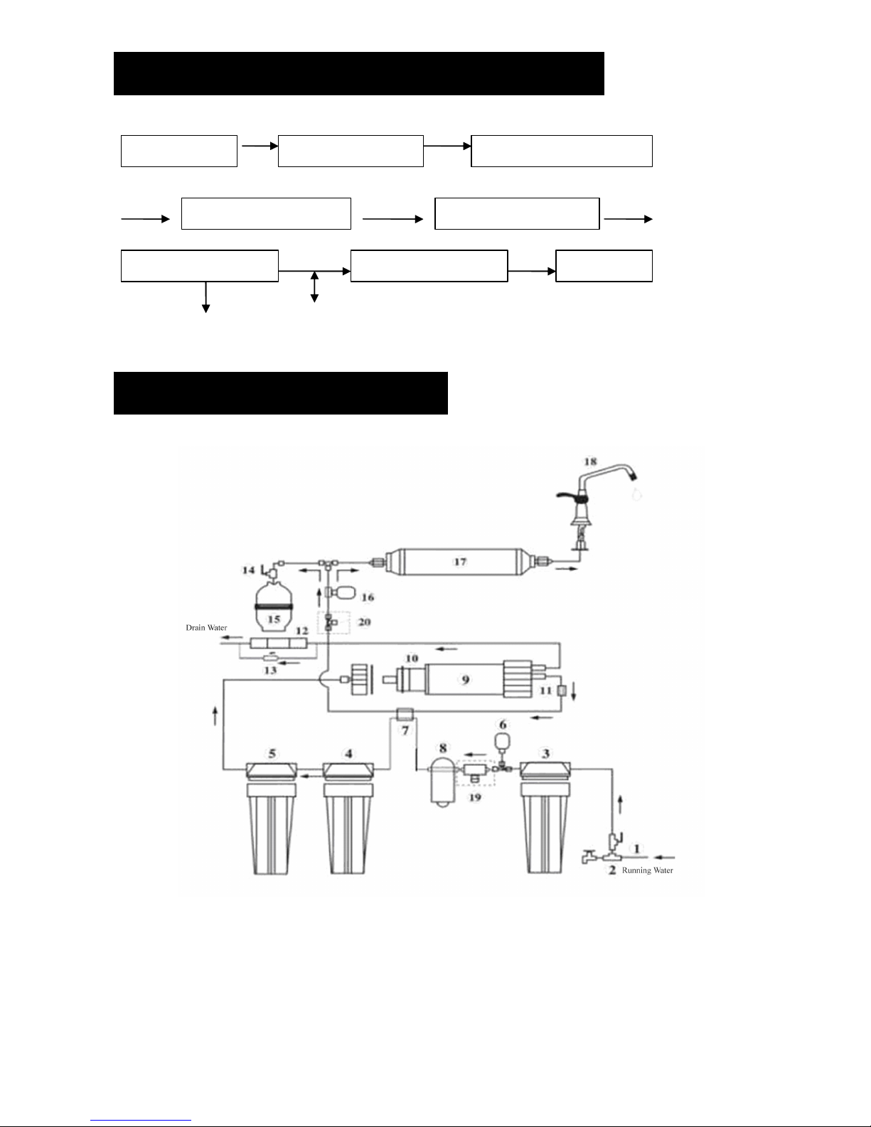
1. Turn on cold water supply valve and feed water valve, but close the tank ball valve.
2.
2.
2.
2. Open the goose faucet. (Pull the b lack handle to the open position).
3.
3.
3.
3. Check the system, whether leak or not.
4.
4.
4.
4. After about 5 minutes, the water starts dripping out of the goose faucet, and let it drip for about 10 minutes,
push the handle to the closed position. It will take several hours (about 3.5) for filling up the pressure tank
depending on local water pressure.
DO NOT DRINK THE
WATER
OF THE FIRST TANK PRODUCED BY YOUR NEWLY PURCHASED
SYSTEM.
5.
5.
5.
5. When the tank is full (you will know the water producing stop), flush the system by pilling the goose faucet to
the open position until the water is completely discharged.
6.
6.
6.
6. Upon completely discharging the water of pressure tank, push the handle to closed position on goose faucet,
and then start the water producing process again . This process should take about 2-2.5 hours until full.
7.
7.
7.
7. After the second tank is filled, now you can enjoy the purified water.
8.
8.
8.
8. Check for leaking daily at the first week and periodically after one week.
9.
9.
9.
9.
You
may notice milky colored water at the first week. It is the air bubble in the water. It is normal and safe.

Ⅹ.
.
.
. MAINTATENANCE
MAINTATENANCE
MAINTATENANCE
MAINTATENANCE
To ensure the system operate at its optimum level, certain routine maintenance must be performed. Frequency of
maintenance performance will depend on feed water quality and level of system usage.
* Change PP spun fiber filter as required or every 3 to 6 months depending on raw water quality and
consumption .
* Change G ranular Carbon Filter and Block Carbon Filter every 6 to 12 months.
* Change RO membrane as required or every 24 to 36 months.
* Change Post Carbon Filter every 6 to 12 months.
* If you are not going to use the system for a long time (you are on a holiday, tour, etc.) , please make sure that
you disconnect the power supply, turn off the raw water supply and drain the tank.
1.
1.
1.
1. Change
Change
Change
Change the
the
the
the filter
filter
filter
filter cartridges.
cartridges.
cartridges.
cartridges.
1.1.
1.1.
1.1.
1.1. Prepare the wrench.
1.2.
1.2.
1.2.
1.2. Close the Feed Water Valve.
1.3.
1.3.
1.3.
1.3. Close the Tank ball valve.
1.4.
1.4.
1.4.
1.4. Take the housing away
from the RO Unit by
wrench.
1.5.
1.5.
1.5.
1.5. Change the filter cartridges.
1.6.
1.6.
1.6.
1.6. After finish changing the
cartridges, can product the
pure water again.
2.
2.
2.
2. Change
Change
Change
Change the
the
the
the Membrane.
Membrane.
Membrane.
Membrane.
2.1.
2.1.
2.1.
2.1. Close the Feed Water Valve.
2.2.
2.2.
2.2.
2.2. Close the Tank ball valve.
2.3.
2.3.
2.3.
2.3. R evolve the hexangular screw,
and take it away.
2.4.
2.4.
2.4.
2.4. Take the Cover away from
the Membrane housing by
wrench.
2.5.
2.5.
2.5.
2.5. Take out the Membrane
from the Membrane housing.
2.6.
2.6.
2.6.
2.6. Put the New Membrane
into the Membrane housing.

NOTE:
NOTE:
NOTE:
NOTE:
Filters and membrane are consumables. Their replacement time is depending on the quality of raw water and
water consumption. If perform the safe frequency of changing, which can guarantee the normal running of RO
system and water quality of the output pure water, so, the above suggestion of filter cartridge changing is only for
reference .
Ⅺ.
.
.
. NOTICE
NOTICE
NOTICE
NOTICE ITEM
ITEM
ITEM
ITEM
1.
1.
1.
1. Please don ’ t pull down the spare part on the machine , so as not to leak, damage the machine.
2.
2.
2.
2. There is an air valve on the pressure tank , please don ’ t release the air from the tank.
3.
3.
3.
3. Don ’ t use the inapposite power supply .
4.
4.
4.
4.
You
should pull out the plug when you don ’ t use the system for a long time, and close the feed water valve.
5.
5.
5.
5. If you don ’ t use the system for a long time, you should operate it same as the initial operation.
6.
6.
6.
6.
You
s hould be careful while unloading, carrying, and installing.
Ⅻ
.
.
.
. TROUBLE
TROUBLE
TROUBLE
TROUBLE SHOOTING
SHOOTING
SHOOTING
SHOOTING GUIDE
GUIDE
GUIDE
GUIDE
Problem
Problem
Problem
Problem Cause
Cause
Cause
Cause Solution
Solution
Solution
Solution
No
No
No
No product
product
product
product water
water
water
water Water supply is turned off Turn on feed water
No
No
No
No enough
enough
enough
enough product
product
product
product
water
water
water
water
1
1
1
1. Water supply is blocked
2
2
2
2. Clogged pre-filter cartridge(s)
3.
3.
3.
3. Feed water valve is plugged or closed
4.
4.
4.
4. Tank ball valve is closed
5.
5.
5.
5. No drain flow, the Drain Restrictor is
plugged
1
1
1
1. Clear restriction
2
2
2
2. Replace pre-filter cartridge(s)
3.
3.
3.
3. Open valve or unclog
4.
4.
4.
4. Open valve
5.
5.
5.
5. Clear or replace Drain Restrictor
Pump
Pump
Pump
Pump not
not
not
not work
work
work
work
1
1
1
1. Low feed water pressure
2
2
2
2. No power supply or l oose electrical
connection
3
3
3
3. Burnt Adopter
1
1
1
1. Check source water line pressure
2
2
2
2. Turn on power supply
3
3
3
3. Replace the adopter or repair it
Pump
Pump
Pump
Pump working
working
working
working but
but
but
but not
not
not
not
producing
producing
producing
producing water
water
water
water
1
1
1
1. Pre-filter carbon cartridge clogging
2
2
2
2. Water inlet solenoid valve failed
1
1
1
1. Check and replace the cartridge
2
2
2
2. Check and replace the solenoid valve
System
System
System
System does
does
does
does not
not
not
not shut
shut
shut
shut off
off
off
off High pressure switch is not working Replace high pressure switch or repair it
Abnormal
Abnormal
Abnormal
Abnormal cycling
cycling
cycling
cycling of
of
of
of
noise
noise
noise
noise
Pre-filter clogging or low feed water
pressure
Change the filter or adjust sufficient feed
water
No
No
No
No drain
drain
drain
drain water
water
water
water Clogged drain restrictor . Replace drain restrictor .
Water
Water
Water
Water has
has
has
has offensive
offensive
offensive
offensive taste
taste
taste
taste
or
or
or
or odor
odor
odor
odor
Post-carbon filter is depleted Drain pressure tank and replace post-carbon
filter
Leak
Leak
Leak
Leak s
s
s
s
1
1
1
1. Pipe not connected tightly
2
2
2
2. Defective tube
3
3
3
3. “ O ” ring has not seated properly
4
4
4
4. “ O ” ring has cracked
1
1
1
1. Tighten the fitting
2
2
2
2. Cut damaged area from pipe or replace
the pipe
3
3
3
3. Remove “ O ” ring and reset it
4
4
4
4. Replace “ O ” ring

ⅫⅠ .
.
.
. NSF
NSF
NSF
NSF STARDARD
STARDARD
STARDARD
STARDARD LISTING
LISTING
LISTING
LISTING
DRINKLING
DRINKLING
DRINKLING
DRINKLING
WATER
WATER
WATER
WATER
CONTAMINANTS
CONTAMINANTS
CONTAMINANTS
CONTAMINANTS AND
AND
AND
AND THEIR
THEIR
THEIR
THEIR CONTROL
CONTROL
CONTROL
CONTROL
WITH
WITH
WITH
WITH reverse
reverse
reverse
reverse osmosis
osmosis
osmosis
osmosis water
water
water
water treatment
treatment
treatment
treatment system
system
system
system
The
The
The
The reverse
reverse
reverse
reverse osmosis
osmosis
osmosis
osmosis water
water
water
water treatment
treatment
treatment
treatment system
system
system
system consists
consists
consists
consists o
o
o
o f
f
f
f pre-treatment,
pre-treatment,
pre-treatment,
pre-treatment, RO
RO
RO
RO membrane,
membrane,
membrane,
membrane, and
and
and
and post
post
post
post treatment.
treatment.
treatment.
treatment.
Reverse
Reverse
Reverse
Reverse osmosis
osmosis
osmosis
osmosis membrane
membrane
membrane
membrane NSF
NSF
NSF
NSF standard
standard
standard
standard 58
58
58
58 listed
listed
listed
listed
Inorganic contaminant % rejection CTA* % rejection TFC*
Cations
Cations
Cations
Cations
Sodium 90-93 99
Calcium 94-97 99
Magnesium 96-98 99
Potassium 87-94 99
Iron 95-98 99
Manganese 98-99 99
Aluminum 86-92 99
Ammonium 94-97 97
Copper 98-99 99
Nickel 98-99 99
Zinc 98-99 99
Strontium 98-99 99
Cadmium 96-98 99
Silver 93-98 98
Mercury 96-98 98
Barium 96-98 99
Chromium 96-98 99
Lead 96-98 99
Anions
Anions
Anions
Anions
Chloride 87-93 99
Bicarbonate 90-95 98
Nitrate 60-75 97
Fluoride 87-93 98
Silicate 85-90 98
Phosphate 98-99 99
Chromate 86-92 99
Cyanide 86-92 95
Sulfate 96-98 99
Thiosulfate 96-99 99
Ferrocyanide 96-99 97
Bromide 87-93 98
Borate 30-50 50
Arsenic 96-99 99
Selenium 94-96 99
Biological
Biological
Biological
Biological &
&
&
& particulate
particulate
particulate
particulate contaminants
contaminants
contaminants
contaminants
Bacteria >99 >99
Protozoa >99 >99
Ameobiccysts >99 >99
Giardia >99 >99
Asbestos >99 >99
Sediment/turbidity >99 >99
Other manuals for RO-50
1
This manual suits for next models
4
Table of contents
Other Purenex Water Filtration System manuals