Bell System Practices KS-14582 Operating and installation instructions
I
I
I
BELL SYSTEM PRACTICES SECTION 081-330-100
AT&TCo Standard Issue 4, May 1972
KS-14582 11 AND 12 SOLDERING COPPERS
AND KS-14768 HEAT UNITS
DESCRIPTION AND USE
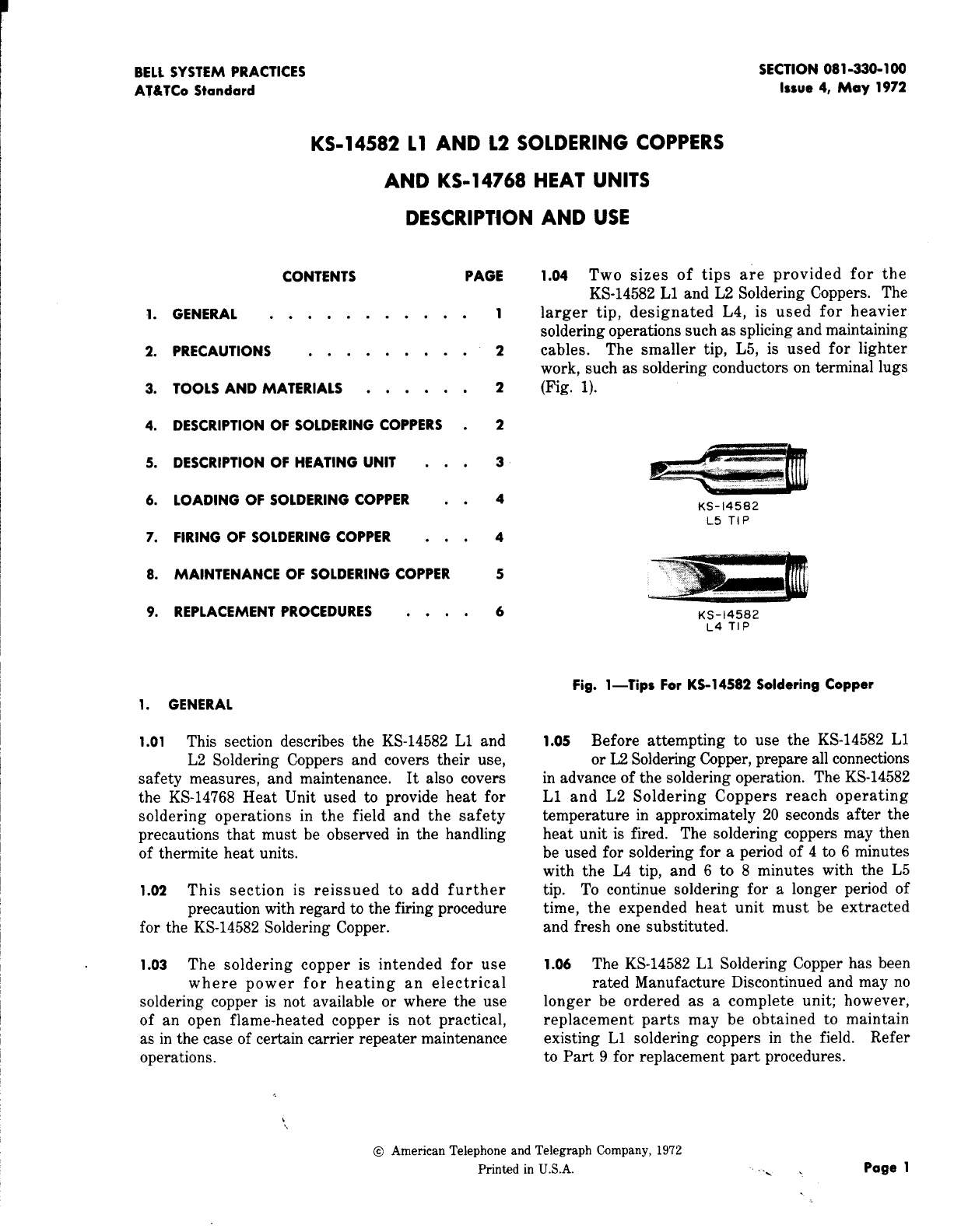
CONTENTS PAGE 1.o4 Two sizes of tips are provided for the
I. GENERAL ..........
2. PRECAUTIONS .....0. .
3. TOOLS AND MATERIALS .....
4. DESCRIPTION OF SOLDERING COPPERS
5. DESCRIPTION OF HEATING UNIT . .
6. LOADING OF SOLDERING COPPER .
7. FIRING OF SOLDERING COPPER . .
8. MAINTENANCE OF SOLDERING COPPER
9. REPLACEMENT PROCEDURES . . .
1. GENERAL
1.01 This section describes
L2 Soldering Coppers
.
.
.
.
.
.
.
.
the KS-14582 L1 and
and covers their use,
KS-14582 L1 and L2 Soldering Coppers. The
1larger tip, designated L4, is used for heavier
soldering operations such as splicing and maintaining
2cables. The smaller tip, L5, is used for lighter
work, such as soldering conductors on terminal lugs
2(Fig. 1).
2
3
4
4
5
6
KS-14582
L5 TIP
,,. “,.
KS-14582
L4 TIP
—
safety measures, and maintenance. It also covers
the KS-14768 Heat Unit used to provide heat for
soldering operations in the field and the safety
precautions that must be observed in the handling
of thermite heat units.
1.o2 This section is reissued to add further
precaution with regard to the firing procedure
for the KS-14582 Soldering Copper.
1.o3 The soldering copper is intended for use
where power for heating an electrical
soldering copper is not available or where the use
of an open flame-heated copper is not practical,
as in the case of certain carrier repeater maintenance
operations.
Fig. l—lips For KS-1 4582 Soldering Copper
1.o5 Before attempting to use the KS-14582 L1
or L2 Soldering Copper, prepare all connections
in advance of the soldering operation. The KS-14582
L1 and L2 Soldering Coppers reach operating
temperature in approximately 20 seconds after the
heat unit is fired. The soldering coppers may then
be used for soldering for aperiod of 4to 6minutes
with the L4 tip, and 6to 8minutes with the L5
tip. To continue soldering for alonger period of
time, the expended heat unit must be extracted
and fresh one substituted.
1.06 The KS-14582 L1 Soldering Copper has been
rated Manufacture Discontinued and may no
longer be ordered as acomplete unit; however,
replacement parts may be obtained to maintain
existing L1 soldering coppers in the field. Refer
to Part 9for replacement part procedures.
@American Telephone and Telegraph Company, 1972
Printed in U.S.A. ..,. Page 1

SECTION 081-320-100
2. PRECAUTIONS
2.01 Precautions To Be Observed With the
Soldering i%ppem:
(a) To avoid injury to personnel or damage to
the copper, do not open the copper for at
least 10 minutes after firing aheat unit.
(b) Do not hold the copper near the hands or
face to test its temperature; serious burns
may result. Use rosin core solder to check
whether the copper has reached soldering
temperature.
(c) Do not place aheated copper on the floor,
on equipment, or in any place other than a
suitable holder such as the 504A Soldering Copper
Holder. Do not remove the copper from its
holder to store it, as in atool kit, until the
copper has thoroughly cooled and the expended
heat unit has been removed. When the copper
is not in use, make sure the heat unit chamber
is empty.
(d) To prevent losing or damaging parts, make
sure the copper is assembled before storing
it.
(e) Never heat the copper over an open flame
to bring it to soldering temperature. This
would damage the copper.
2.o2 l?recautiom To Be Observed With Heat
units:
(a) Use only standard heat units equipped with
aprotective cap stamped KS-14768. Do not
use commercially available nonstandard heat units.
(b) Aheat unit should be fired only in the
copper and never by any other means. To
do otherwise is hazardous.
WARNING: Ignited outiide the soldering
.copper, the heat unit becomes white hoti
Molten thermi”temay splatter. Adhere to
operating instructions in Parts 6and 7
of this section.
(c) Do not store heat units near very hot objects.
(d) Do not remove heat tmits
until they are to be used.
Page 2
from the carton
3. TOOLS AND MATERIALS
CODE OR
SPEC NO.
TOOLS
504A
AT-8420
KS-14164
R-1482
R-5850
—
—
—
MATERIALS
KS-2423
KS-7470
—
—
—
DESCRIPTION
Soldering Copper Holder (or
other suitable holder)
Combination Pliers, B
Brush
File
5/8- and 3/41nch Open Double
End Offset Hex Wrench
BR-34 Brush
}
Kemode Manu-
RM-12 Reamer facturing Co.
Carborundum Unfinished Stick,
4 by 1/2 Inch Square, Grading
C60-P-VUF, Carborundum Co. or
Equivalent
Cloth
oil
Pipe
Cleaners obtain locdy)
Standard Rosin Core Wire Solder
“Dag” Dispersion No. 41, AcheSon
Colloids Corp.
4. DESCRIPTION OF SOLDERING COPPERS
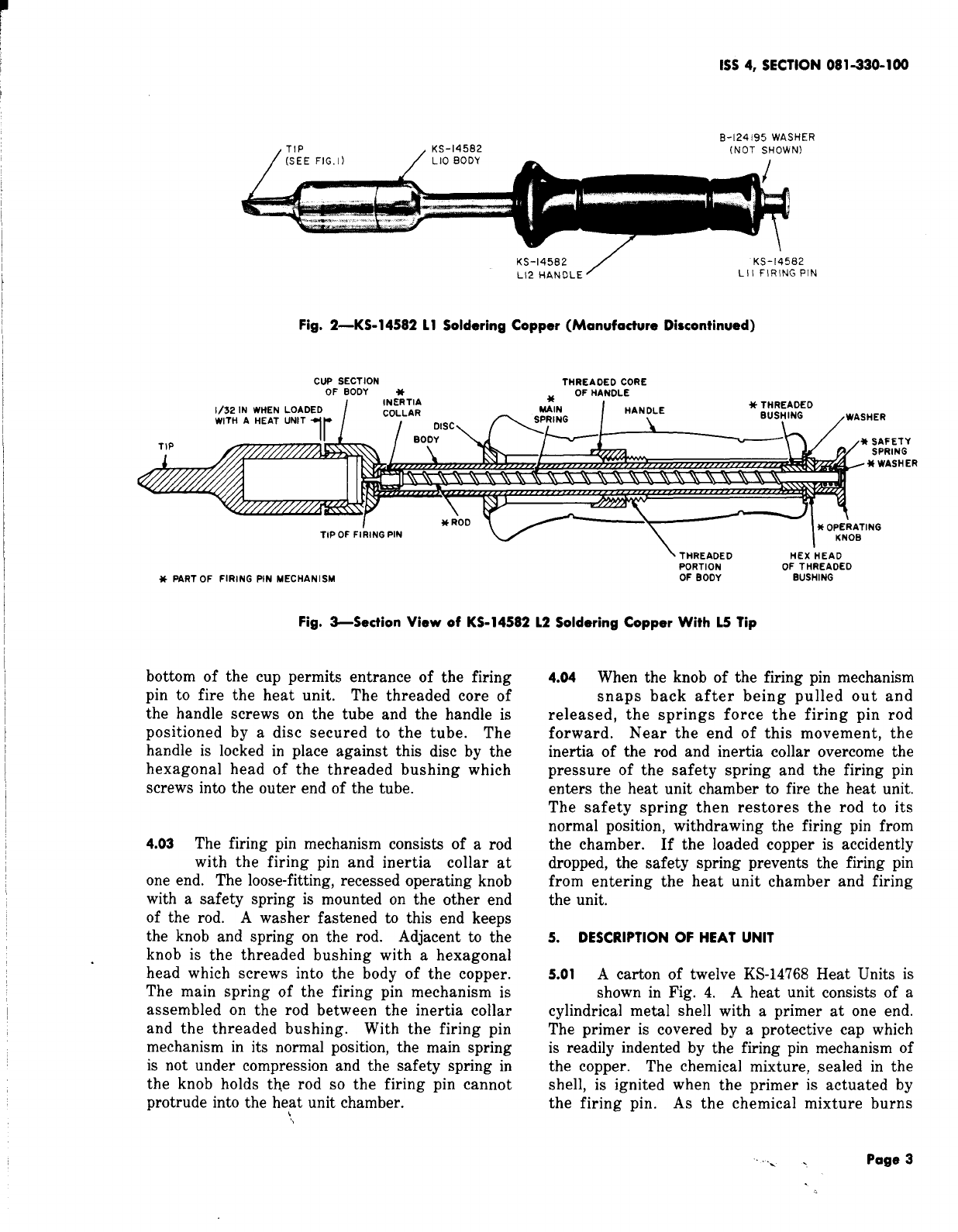
4.o1 The KS-14582 L1 and L2 Soldering Coppers
(Fig. 2and 3) are conventional appearing
soldering coppers which are heated by means of a
chemically charged heat unit (K$+14768)placed in
achamber in the tip of the copper. The heat
unit is actuated by afiring pin mechanism mounted
in the handle of the copper. The handle is similar
to that of the KS-8740 Electric Soldering Copper
so the copper may be stored in the 504A Soldering
Copper Holder.
4.o2 Asection view of the KS-14582 L2 Soldering
Copper is shown in Fig. 3. The body of
the copper consists of atube having acupshaped
section at one end. The heat unit chamber of the
tip screws into this cup and asmall hole in the
., .
1SS4, SECTION 081-330-100
B-124195 WASHER
,TIP ,KS-14582 (NOT SHOWN)
KS-14582
L12 HANDLE /
Fig. 2—KS-1 458211 Soldering Copper (Manufacture
CUP SECTION THREAOEO CORE
OF BOOY *OF 14ANOLE
KS-14582
Lll FIRING PIN
Discontinued)
ETY
ING
SHER
\THREAOED HEX “HEAD
PORTION
*PART OF FIRING PIN MECHANISM OF THREAOEO
OF BOOY BUSHING
Fig. 3-Section View of KS-14582 12 Soldering Copper With 15 Tip
bottom of the cup permits entrance of the firing
pin to fire the heat unit. The threaded core of
the handle screws on the tube and the handle is
positioned by adisc secured to the tube. The
handle is locked in place against this disc by the
hexagonal head of the threaded bushing which
screws into the outer end of the tube.
4.o3 The firing pin mechanism consists of arod
with the firing pin and inertia collar at
one end. The loose-fitting, recessed operating knob
with asafety spring is mounted on the other end
of the rod. Awasher fastened to this end keeps
the knob and spring on the rod. Adjacent to the
knob is the threaded bushing with ahexagonal
head which screws into the body of the copper.
The main spring of the firing pin mechanism is
assembled on the rod between the inertia collar
and the threaded bushing. With the firing pin
mechanism in its normal position, the main spring
is not under compression and the safety spring in
the knob holds the rod so the firing pin cannot
protrude into the heat unit chamber.
L
4.o4 When the knob of the firing pin mechanism
snaps back after being pulled out and
released, the springs force the firing pin rod
forward. Near the end of this movement, the
inertia of the rod and inertia collar overcome the
pressure of the safety spring and the firing pin
enters the heat unit chamber to fire the heat unit.
The safety spring then restores the rod to its
normal position, withdrawing the firing pin from
the chamber. If the loaded copper is accidently
dropped, the safety spring prevents the firing pin
from entering the heat unit chamber and firing
the unit.
5. DESCRIPTION OF HEAT UNIT
5.01 Acarton of twelve KS-14768 Heat Units is
shown in Fig. 4. Aheat unit consists of a
cylindrical metal shell with aprimer at one end.
The primer is covered by aprotective cap which
is readily indented by the firing pin mechanism of
the copper. The chemical mixture, sealed in the
shell, is ignited when the primer is actuated by
the firing pin. As the chemical mixture burns
... . Page 3

SECTION 081-330-100
without generating or releasing gases, the unit is
entirely safe for use within the copper. However,
should the unit be ignited outside the copper,
contact with the air would cause it to become
white hot and therefore, afire hazard.
PROTECTIVE CAP
COVERING PRIMER
\ I METAI
Fig. 4-KS-1 4768 Heat Units
Note: When inserting aKS-14768 Heat Unit
into aKS-14582 L1 or L2 Soldering Copper,
make certain the heat unit is firmly clamped
between the bottom of the heat unit chamber
(L4 or L5 tip) and the inside top of the cup
section of the body and that there is aspace
between the shoulders of the two, at least
l/32-inch, as shown in Fig. 3.
6. LOADING OF SOLDERING COPPER
6.01 While the tool is cold, check that the firing
pin mechanism and body are securely tightened
against the handle before loading the tool. If
necessary, tighten the body manually, and use the
R-5850 Wrench to tighten the threaded bushing of
the firing pin mechanism.
6.02 To load the copper when it is cold, unscrew
the tip and place the KS-14768 Heat Unit
into the hollow chamber of the tip with the primer
end of the unit facing outwards. Remount the tip
on the copper fingertight.
6.03 If it is necessary to reload the copper when
it is hot in order to a,ontinue soldering
operations, allow the copper to cool for at least
10 minutes after firing (2 or 3minutes after the
heat unit is expended), Earlier removal of the tip
may cause the heat unit to expand on contact with
the air to such an extent that it will be difficult
to remove. To remove the tip while hot, proceed
as follows: While holding the handle firmly in
one hand, grasp the tip just behind the wedgeshaped
end with the combination pliers, and loosen the
tip. Then hold the tip stationary with the pliers
and unscrew the body of the copper from the tip
by turning the handle manually. While doing this,
take care to hold the copper with the tip pointed
downwards to prevent the heat unit from dropping
out. When the tip is free of the body, invert the
tip over ametal receptacle, or on the ground at
some safe location, so the heat unit drops out of
the chamber.
Caution: Do not discard the hot heat
um”ton or near flammable materials.
6.04 Place the body of the copper in asuitable
holder such as the 504A Soldering Copper
Holder. While holding the tip with the pliers,
insert afresh heat unit into the chamber of the
tip with the primer end of the unit facing outward.
Screw the body of the copper on the tip. Take
care not to tighten the tip excessively as this would
make it difficult to remove if necessary to again
reload the hot copper to continue soldering.
Caution: likercise care to avoid touctig
the hot tip or body of the copper while
replacing the heat w“t as serious burns
may result
7. FIRING SOLDERING COPPER
7.OI To fire the copper, hold the handle firmly
in one hand and grasp the knob of the firing
pin mechanism between the thumb and forefinger
of the other hand.
Caution: As the tip of the copper heats
rapidkyafter tiring, take care to hold the
copper away tkm the body at about an
arms length and pointed so the handIe
end does not face the body.
$Pull the firing pin knob out as far as it will go
and allow it to snap back. When the firing pin
hits, it will actuate the primer in the heat unit.
There will not be a“pop” or “bang” but the heat
Page 4

1SS4, SECTION 081-330-100
unit will very likely have ignited and started heating
the copper. The soldering copper will be ready
for operation in about 20 seconds.+ The copper
may then be used for soldering for aperiod of 4
to 6minutes with the L4 tip and 6to 8minutes
with the L5 tip.
7.02 FaiZureof (%pper to Fire: If the copper
fails to become hot in approximately 20
seconds, repeat the firing procedure covered in
7.01. $Be sure to determine that the copper has
not started to heat before refiring or removing a
heat unit to avoid the danger of splattering molten
thermite.~ If the copper does not fire after three
or four attempts, the heat unit may be defective.
Remove the unfired heat unit and try anew heat
unit. If the copper still fails to fire, the firing
pin hole in the body of the copper may be blocked
or the firing pin mechanism may be worn. Clean
the body of the copper and firing pin mechanism
as covered in 8.08 through 8.14, If, after cleaning,
the copper frequently fails to fire, the firing pin
mechanism should be replaced as covered in 9.03.
Note: Defective heat units should be disposed
of along with other metallic trash. They
should not be thrown away with paper trash
or other combustible material.
8. MAINTENANCE OF COPPER
Tinning Soldering Copper
8.01 When necessary, tin the tip of the copper
as covered in 8.02 through 8,04.
8.02 With the copper cold, file the surface of
one side of the tip for adistance of
approximately 1/4 inch from the end until it is
bright and clean using the R-1482 file,
8.03 Luad the copper as covered in 6.02.
8.04 Fire the copper as covered in 7.01. When
the copper reaches soldering temperature,
quickly file the side of the point which was previously
cleaned, and apply rosin core solder, spreading
the solder by means of the wiping pad of the 504A
Soldering Copper Holder or similar tin plate surface.
Repeat this operation until the filed surface is well
tinned. Only one side of the copper tip should be
tinned. This tends to keep the hot solder in contact
with the surface to ,be soldered and prevents the
solder from collecting on the under side of the
copper when working on vertical terminals.
Cleoning lip Chomber
8.05 In order to permit easy removal of the
KS-14768 Heat Unit, clean the inside of the
tip chamber when soldering operations have been
completed and the copper has cooled.
8.06 To clean the chamber, unscrew the tip from
the body of the copper and dispose of the
expended heat unit. Hold the tip firmly in one
hand and insert the BR-34 Brush into the chamber
as far as it will go. Turn the brush in aclockwise
direction several times. Remove the brush and
shake the loosened foreign matter out of the
chamber. Repeat this procedure until the chamber
is clean. Check the threads on the tip and, if
necessary, clean them using the brush. After
cleaning and before remounting the tip, lubricate
the threads of the tip as covered in 8.07.
Note: Thorough cleaning of the tip chamber
is essential to prevent difficulty in removing
aspent heat unit.
Lubricating Threads of lip
8.07 Periodic lubrication of the threads of the tip
will facilitate removal of the tip. When
necessary to apply the lubricant, remove all traces
of old lubricant using the BR-34 Brush and apply
“Dag” Dispersion No. 41 to the threads with the
KS-14164 Brush. If the tip is worn so it is not
held securely to the body of the copper, replace
the tip.
Cleaning Body and Firing Pin Mechanism
8.o8 Clean the body and firing pin mechanism
at the end of each day if the copper has
been used continuously. However, if the copper
is used intermittently, ie, only several times aday,
clean the parts at least once aweek to obtain
proper operation of the firing mechanism. Clean
the parts only when the copper is cold.
8.09 Manually unscrew the tip. Remove the firing
pin mechanism using the R-5850 Wrench,
taking care that the washer in the recessed end
of the handle is not lost. To clean the body, fully
insert the RM-12 Reamer into the tube opening at
the handle end. Turn the reamer clockwise several
...,. Page 5
SECTION 081-330-100
r
times. Remove the reamer and shake out any
loosened foreign matter from the tube. Repeat
this procedure until no more foreign matter can
be shaken out. Clean the firing pin hole using a
pipe cleaner. Check the threads in the cup and
if necessary, clean them using the BR-34 Brush.
Note: Thorough cleaning of the body as
described above is essential, as an accumulation
of foreign matter at the firing pin hole end
may not allow proper penetration of the firing
pin into the heat unit chamber.
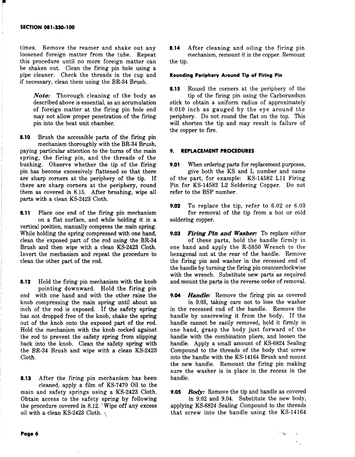
8.10 Brush the accessible parts of the firing pin
mechanism thoroughly with the BR-34 Brush,
paying particular attention to the turns of the main
spring: the firing pin, and the threads of the
bushing. Observe whether the tip of the firing
pin has become excessively flattened so that there
are sharp comers at the periphery of the tip. If
there are sharp corners at the periphery, round
them as covered in 8.15. After brushing, vvipe all
parts with aclean KS-2423 Cloth.
8.11 Place one end of the firing pin mechanism
on aflat surface, and while holding it in a
vertical position, manually compress the main spring.
While holding the spring compressed with one hand,
clean the exposed part of the rod using the BR-34
Brush and then wipe with aclean KS-2423 Cloth.
Invert the mechanism and repeat the procedure to
clean the other part of the rod.
8.12 Hold the firing pin mechanism with the knob
pointing downward. Hold the firing pin
end with one hand and with the other raise the
knob compressing the main spring until about an
inch of the rod is exposed. If the safety spring
has not dropped free of the knob, shake the spring
out of the knob onto the exposed part of the rod.
Hold the mechanism with the knob cocked against
the rod to prevent the safety spring from slipping
back into the knob. Clean the safety spring with
the BR-34 Brush and wipe with aclean KS-2423
cloth.
8.13 After the firing pin mechanism has been
cleaned, apply afilm of KS-7470 Oil to the
main and safety springs using aKS-2423 Cloth.
Obtain access to the safety spring by following
the procedure covered in 8.12. “Wipe off any excess
oil with aclean KS-2423 Cloth. ~,
8.14 After cleaning and oiling the firing pin
mechanism, remount it in the copper. Remount
the tip.
Rounding Periphery Around Tip of Firing Pin
8.15 Round the corners at the periphery of the
tip of the firing pin using the Carborundum
stick to obtain auniform radius of approximately
0.010 inch as gauged by the eye around the
periphery. Do not round the flat on the top. This
will shorten the tip and may result in failure of
the copper to fire.
9. REPLACEMENT PROCEDURES
9.o1 When ordering parts for replacement purposes,
give both the KS and Lnumber and name
of the part, for example: KS-14582 L11 Firing
Pin for KS-14582 L2 Soldering Copper. Do not
refer to the BSP number.
9.o2 To replace the tip, refer to 6.02 or 6.03
for removal of the tip from ahot or cold
soldering copper.
9.o3 Firing Pin and Waden To replace either
of these parts, hold the handle firmly in
one hand and apply the R-5850 Wrench to the
hexagonal nut at the rear of the handle. Remove
the firing pin and washer in the recessed end of
the handle by turning the firing pin counterclockwise
with the wrench. Substitute new parts as required
and mount the parts in the reverse order of removal.
9.o4 Hadle: Remove the firing pin as covered
in 9.03, taking care not to lose the washer
in the recessed end of the handle. Remove the
handle by unscrewing it from the body. If the
handle cannot be easily removed, hold it firmly in
one hand, grasp the body just forward of the
handle with the combination pliers, and loosen the
handle. Apply asmall amount of KS-6824 Sealing
Compound to the threads of the body that screw
into the handle with the KS-14164 Brush and mount
the new handle. Remount the firing pin making
sure the washer is in place in the recess in the
handle.
9.OS Body: Remove the tip and handle as covered
in 9.02 and 9.04. Substitute the new body,
applying KS-6824 Sealing Compound to the threads
that screw into the handle using the KS-14164
Page 6..,?

1SS4, SECTION 081-330-100
Brush. Remount the parts in the reverse order
of removal.
9.06 Fig. 5illustrates the components of the
KS-14582 L2 Soldering Copper and associated
I
KS-14582
L14 BODY
TIP [SEE NOTE \
NOTE :
part numbers for the purpose of ordering replacement
parts. Note that the tips, firing pin, and B-124195
Washer are interchangeable for either the L1 or
L2 Soldering Coppers. See Fig. 2.
B-124195 wASHER
KS-14582 tNOT SHOWN)
L13 HANOLE \
KS-14%82 Lll
FIRING PIN
THE KS-14582 L2 SOL OERING COPPER
IS FUR NISHEO WITH TIP, WHICH MUST BE
SPECIFIED IN THE ORDER.
Fig. 5-KS-1 458212 Soldering Copper
., . Page 7
7Pages
This manual suits for next models
1
Table of contents


