Vitronics Soltec mySelective 6748 Quick start guide

Schematics & Parts
mySelective 6748
Version 48.1.0.007
VITRONICS SOLTEC BV
Visit adress Innovatiepark 12 - 4906 AA Oosterhout - the Netherlands
Mail adress P.O. Box 143 - 4900 AC Oosterhout - the Netherlands
Telephone +31-162-483000
Fax +31-162-483269
www.vitronics-soltec.com

ii
Rights
COPYRIGHT 2010 VITRONICS SOLTEC BV
All rights reserved. No part of this publication may be reproduced, stored in a retrieval system, or transmitted in any form or by any
means, electronic, mechanical, photocopying, recording or otherwise, without the prior written permission of Vitronics Soltec BV.
This publication remains the property of Vitronics Soltec BV and may not be passed, loaned or given to any third party.
Vitronics Soltec BV reserves the right to make changes in design and specifications without notice.
EUROPE
VITRONICS SOLTEC BV VITRONICS SOLTEC GmbH
Innovatiepark 12 Udo-Lermann Str.10
4906 AA Oosterhout 97828 Marktheidenfeld
the Netherlands Germany
Tel. +31-162-483000 Tel. +49-9391-98820
Fax +31-162-483269 Fax +49-9391-988228
AMERICAS
VITRONICS SOLTEC Inc.
2 Marin Way
Stratham, New Hamphire 03885
USA
Tel. +1-603-772-7778
Fax +1-603-772-7776
ASIA PACIFIC
VITRONICS SOLTEC SHANGHAI VITRONICS SOLTEC (SUZHOU) Co. Ltd
Sales Office Manufacturing Plant
858 Zhujiang Lu 858 Zhujiang Lu
Building 2 Building 2
Suzhou New District, China 215129 Suzhou New District, China 215129
Tel. +86-21-5033-7855 Tel. +86-512-6841-3378
Fax +86-21-6360-9449 Fax +86-512-6841-3161
VITRONICS SOLTEC PTE LTD. VITRONICS SOLTEC KOREA
132 Joo Seng Road A-1001, Poonglim Iwant Bldg.
#03-01 Uniplas Building 255-1 Seohyun Dong,
Singapore 368358 Bundang Gu, Seongnam 463-862, Korea
Tel. +65-6484-3010 Tel. +82-31-783-7020
Fax +65-6484-1910 Fax +82-31-783-7021
VITRONICS SOLTEC MALAYSIA
8-2-5 Sunny Point Complex
Jalan Sultan Azlan Shah, Batu Uban,
11700 Penang, Malaysia
Tel. +60-4-658-4227
Fax +60-4-655-4227

Schematics & Parts mySelective 6748 iii
Preface
During the composition of this manual much attention is given to avoid errors
and mistakes. Also we aimed to give the contents a clear structure.
If during the use of this manual errors or incomplete descriptions are found, or
the reader considers that improvements are necessary to overcome any in-
accuracies, please inform us. We appreciate any comments which will help us to
improve this documentation.
For corrections or clarifications please contact:
1. By mail:
VITRONICS SOLTEC BV
HEAD OFFICE
TECHNICAL PUBLICATIONS
P.O. BOX 143
4900 AC OOSTERHOUT
THE NETHERLANDS
TEL NR. (31) - 162483000
FAX.NR. (31) - 162483285
OR
2. By e-mail:
techpub.nl@vsww.com

iv

Schematics & Parts mySelective.com v
Table of Contents
Preface iii
Table of Contents v
1Schematics 1-1
1.1 General . . . . . . . . . . . . . . . . . . . 1-1
2 Parts 2-1
2.1 PLC controller . . . . . . . . . . . . . . . . . 2-1
2.1.1 Configuration Controllers . . . . . . . . . . . 2-2
2.2 Servo controller . . . . . . . . . . . . . . . . 2-4
2.3 Frequency inverter controller . . . . . . . . . . . 2-5
2.4 Thermic protection relay . . . . . . . . . . . . . 2-6
2.5 Power supply . . . . . . . . . . . . . . . . . 2-7
2.5.1 Adjustment power supply . . . . . . . . . . . 2-7
2.6 Safety module . . . . . . . . . . . . . . . . . 2-8
2.6.1 Jumper settings safety module . . . . . . . . . . 2-8
2.7 E-stop module . . . . . . . . . . . . . . . . . 2-9
2.8 Interconnection module . . . . . . . . . . . . . 2-10
2.8.1 Drawing IMC2900 . . . . . . . . . . . . . 2-10
2.9 Opto modules . . . . . . . . . . . . . . . . . 2-11
2.10 Sensor PCB detect . . . . . . . . . . . . . . . 2-12
2.10.1 Working principle. . . . . . . . . . . . . . 2-12
2.10.2 Adjustment procedure . . . . . . . . . . . . 2-12
2.11 Sensor Infeed & outfeed protection . . . . . . . . . 2-13
2.12 Sensors Blockings . . . . . . . . . . . . . . . . 2-14
2.12.1 Adjustment sensor optical WLL260 . . . . . . . . 2-14
2.13 Sensors Pneumatic cylinders - type 1 . . . . . . . . . 2-15
2.13.1 Adjustment procedure sensors MultiWave . . . . . . 2-16
2.13.2 Adjustment procedure sensors SecureGrip . . . . . . 2-16
2.14 Sensors Pneumatic cylinders - type 2 . . . . . . . . . 2-17
2.14.1 Adjustment procedure sensors lifting unit transport system . 2-17
2.14.2 Adjustment procedure sensor SecureGrip . . . . . . 2-18

vi
2.14.3 Adjustment procedure sensors wave height measurement (WHM)
2-18
2.15 Sensors Doors control . . . . . . . . . . . . . . 2-19
2.16 Sensors Robot & MultiFlux positions . . . . . . . . . 2-20
2.17 Solderpot and Conveyor width limit switch . . . . . . . 2-21
2.18 Thermostat PT100 - Solderpot & Machine temperature . . 2-22
2.19 Impulse counter Conveyor & Solderpot pumps . . . . . . 2-23
2.20 SolderFeeder sensor . . . . . . . . . . . . . . . 2-24
2.21 Advanced SolderFeed sensor . . . . . . . . . . . . 2-25
2.22 SolderLevel sensor . . . . . . . . . . . . . . . 2-26
2.23 Flux vessel level . . . . . . . . . . . . . . . . 2-27
2.24 Teach camera & led spotlight . . . . . . . . . . . . 2-28
2.24.1 Version 1 . . . . . . . . . . . . . . . . 2-28
2.24.2 Version 2 . . . . . . . . . . . . . . . . 2-29
2.25 Pressure controls . . . . . . . . . . . . . . . . 2-30
2.26 UPS system . . . . . . . . . . . . . . . . . . 2-32
2.26.1 General . . . . . . . . . . . . . . . . . 2-32
2.26.2 Working Principles . . . . . . . . . . . . . 2-32
2.26.3 Remarks. . . . . . . . . . . . . . . . . 2-33
2.26.4 Transport . . . . . . . . . . . . . . . . 2-33
2.26.5 Set-up . . . . . . . . . . . . . . . . . 2-33
2.26.6 Operation . . . . . . . . . . . . . . . . 2-33
2.26.7 Maintenance, servicing and faults . . . . . . . . . 2-34
2.26.8 Indicators and operating controls . . . . . . . . . 2-34
2.26.9 Back panel . . . . . . . . . . . . . . . . 2-36
2.26.10 Slide buttons output voltage . . . . . . . . . . . 2-36
2.27 Adjustment of universal SecureGrip . . . . . . . . . 2-37
2.28 Gripper Adjustment . . . . . . . . . . . . . . . 2-38
2.28.1 General information . . . . . . . . . . . . . 2-38
2.28.2 Tools . . . . . . . . . . . . . . . . . 2-38
2.28.3 Gripper . . . . . . . . . . . . . . . . . 2-39
2.28.4 Adjustment methods . . . . . . . . . . . . . 2-40
2.29 Cables Robot and MultiFlux units . . . . . . . . . . 2-44
3 Trouble Shooting 3-1
3.1 General . . . . . . . . . . . . . . . . . . . 3-1
3.2 UPS system . . . . . . . . . . . . . . . . . . 3-2
3.2.1 Front panel UPS system . . . . . . . . . . . . 3-2
3.3 Frequency inverter . . . . . . . . . . . . . . . 3-3

viii

ICON DESCRIPTION ICON DESCRIPTION
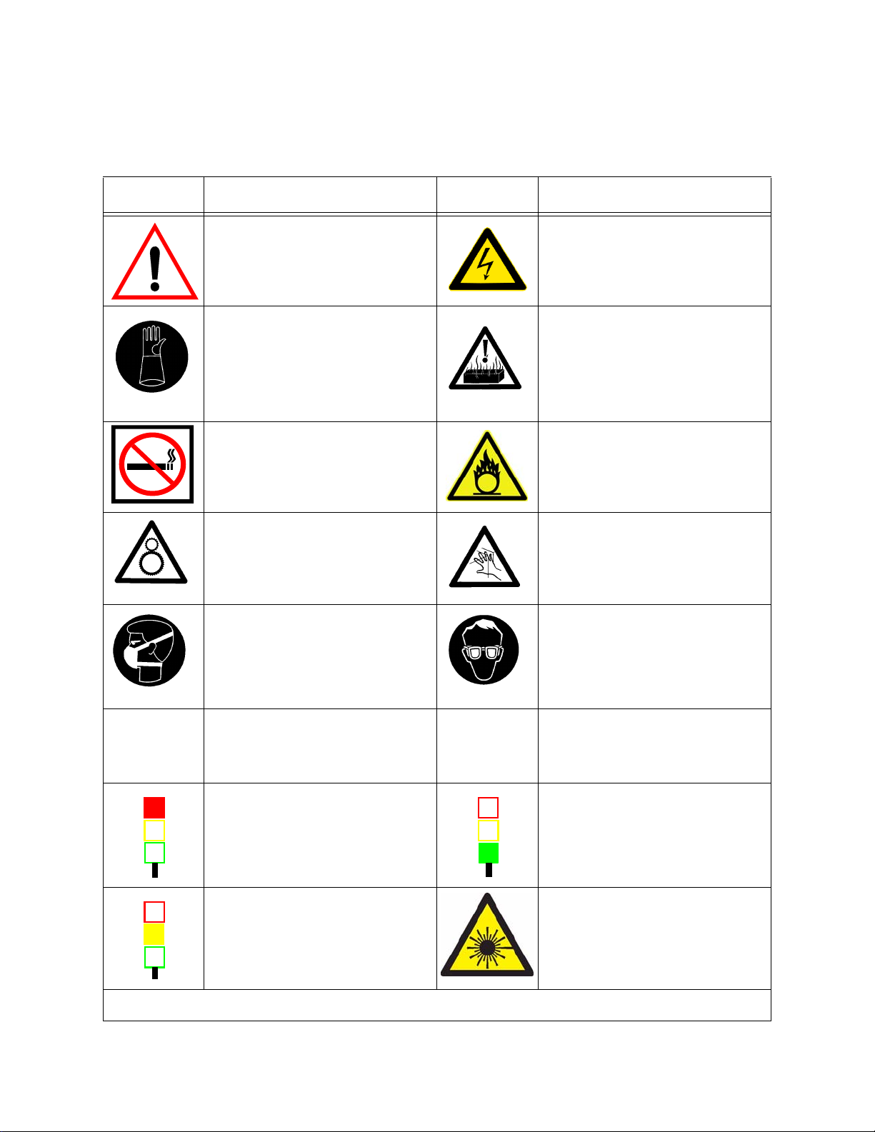
Only Qualified personnel is allowed to work on the
equipment.
Never eat, drink or smoke while working on the
machine.
Wash thoroughly before eating, drinking or smoking.
High voltages are present on various parts of the sys-
tem.
Before working on the electrical circuit, turn main
power off and block the mainswitch with a padlock.
Always wear heat resistant gloves and protective
clothing when working on the machine.
If possible allow the machine to cool down before
starting working on the machine.
When burned, immerse in cold water immediately.
When the burn is severe, consult a physician as soon
as possible.
Always wear heat resistant gloves and protective
clothing when working on the machine.
If possible allow the machine to cool down before
starting working on the machine
When burned, immerse in cold water immediately.
When the burn is severe, consult a physician as soon
as possible.
No smoking or open fire near the machine.
Be sure a fire-extinguisher is in the surroundings of
the machine.
No smoking or open fire near the machine.
Be sure a fire-extinguisher is in the surroundings of
the machine.
All moving parts of the system, including pulleys,
belts, chains, coolingfans, sprocketwheels, vacuum-
doors and cylinders presents a potential danger.
Be careful with covers and doors. Always pay atten-
tion to opening and closing.
The vapours in the board preparation module are
chemical. When the board is heated, a noxious
vapour will be liberated. This vapour must be
extracted. Also the dust on the surface of the solder-
pot is dangerous when inhaled.
Avoid inhaling this vapours / dust by using mouth
protection.
When working on the machine, always protect your
eyes with safety glasses.
Nitrogen
N2
Follow the safety precautions and procedures
described in the Material Safety Data Sheet of
the Nitrogen supplier.
UPS
Uninterruptible
Power Source
When mainswitch is switched OFF for a longer
period, switch the UPS to OFF.
Signal light RED
- E-stop Active
Signal light GREEN
- Steady = Machine Run,
- Flashing slow = Machine not at setpoint, machine
stop
Signal light ORANGE
- Steady = Overload (outfeed full), Machine will
block,
- Flashing slow = Alarm
- Flashing fast = Critical alarm. Machine will block
LASER RADIATION
Do not stare into beam.
Class 2 Laser product.
Only applicable for Soldering machines
equipped with laser measurement systems.
If these rules are not observed it can cause personal injury and/or damage to the machine
SAFETY RULES
GENERAL INFORMATION

.

Schematics & Parts mySelective.com CHAPTER 1 1
Schematics 1
1.1 GENERAL
Included in this chapter are all the drawings and partlists that are part of the machine configura-
tion.
VERSION 2005 December

SCHEMATICS
2CHAPTER 1

8
7
6
5
4
3
2
1
EN 60204-1
+
=
DateVersion Name Norm
Last mod
Checked
Author
Sheet
of
MACHINETYPE DESCRIPTION
INSERT SHEET FOR
PROJECT CODE
1 2
1
3 4
DRAWING LIST
03/12/2008
5678
A
B
C
510583
DRAWINGS
78
D
E
MYSELECTIVE 6748
6748
F
ELECTRIC CIRCUIT DIAGRAM
SHEET SHEET DESCRIPTIONDESCRIPTION
8
7
6
5
4
3
2
1
EN 60204-1
+
=
DateVersion Name Norm
Last mod
Checked
Author
Sheet
of
MACHINETYPE DESCRIPTION
INSERT SHEET FOR
PROJECT CODE
12345678
A
B
C
D
E
F
1 DRAWING LIST
2 MACHINE CONFIGURATION
3 MAIN SUPPLY
4 MAIN SUPPLY PRE-HEATING STATION 2 AND 3
5 MAIN SUPPLY SOLDER POT HEATERS STATION 5 AND 6
6 400 VAC CIRCUIT PREHEATER STATION 2
7 I/O MODULE 5 PREHEATER STATION 2
8 400 VAC CIRCUIT F.C. PREHEATER STATION 2
9 400 VAC CIRCUIT F.C. PREHEATER STATION 2
10 400 VAC CIRCUIT F.C. PREHEATER STATION 2
11 I/0 MODULE 5 F.C. PREHEATER STATION 2
12 I/0 MODULE 14 F.C. PREHEATER STATION 2
13 400 VAC CIRCUIT PREHEATER STATION 3
14 I/O MODULE 6 PREHEATER STATION 3
15 NOZZLE PLATE ELEVATION
16 ADVANCED SOLDER DRAINAGE
17 ADVANCED SOLDER DRAINAGE
18 UPS SYSTEM AND 230VAC POWER DISTRIBUTION
19 SERVO CONTROLLERS X-Y
20 SERVO CONTROLLERS U-Z
21 FREQUENCY INVERTERS CONVEYER
22 FREQUENCY INVERTERS STATION 5
23 FREQUENCY INVERTERS STATION 6
24 230 VAC CIRCUIT
25 SERVO CONTROLLERS MULTI FLUXER STATION 1
26 OPTO COUPLER MULTIFLUXER STATION 1
27 SERVO CONTROLLERS MULTI FLUXER STATION 2
28 OPTO COUPLER MULTI FLUXER STATION 2
29 24 VDC CIRCUIT
30 24 VDC CIRCUIT
31 EMERGENCY STOP AND SAFETY CIRCUIT
32 CONVEYER WIDTH AND PLATE HEIGTH ADJ.
33 OPTO COUPLER 24 VDC TTL
34 OPTO COUPLERS SERVO CONTROLLERS
35 OVERTEMPERATURE PROTECTION CIRCUIT
36 PROCESSOR UNITS
37 MAIN - SLOT 1 ANALOG INPUT (PT100)
38 MAIN - SLOT 2 ANALOGE INPUT UNIVERSAL
39 MAIN - SLOT 3 DIGITAL INPUT (24VDC)
40 MAIN - SLOT 4 DIGITAL INPUT (24VDC)
41 MAIN - SLOT 5 (SPARE)
42 MAIN - SLOT 6 DIGITAL OUTPUT (24VDC)
43 MAIN - SLOT 7 DIGITAL OUTPUT (24VDC)
44 MAIN - SLOT 8 DIGITAL OUTPUT (24VDC)
45 MAIN - SLOT 9 SERIAL COMMUNICATION
46 SLAVE 1 - SLOT 1 DIGITAL INPUT (24VDC)
47 SLAVE 1 - SLOT 2 DIGITAL INPUT (24VDC)
48 SLAVE 1 - SLOT 3 DIGITAL INPUT (24VDC)
49 SPARE
50 SLAVE 1 - SLOT 5 DIGITAL OUTPUT (24VDC)
51 SLAVE 1 - SLOT 6 DIGITAL OUTPUT (24VDC)
52 SLAVE 1 - SLOT 7 DIGITAL OUTPUT (24VDC)
53 SPARE
54 I/O MODULE 1 N2/AIR & MULTI WAVE
55 I/O MODULE 2 N2/AIR & MULTI WAVE
56 I/O MODULE 3 N2/AIR & SELECT FLUXER
57 I/O MODULE 7 FLUX SUPPLY UNIT
58 I/O MODULE 8 SMEMA
59 I/O MODULE 9 CONVEYOR
60 I/O MODULE 10 CONVEYOR
61 I/O MODULE 11 GRIPPER
62 I/O MODULE 12 GRIPPER
63 PARTSLIST PAGE 1
64 PARTSLIST PAGE 2
65 PARTSLIST PAGE 3
66 PARTSLIST PAGE 4
67 PARTSLIST PAGE 5
68 PARTSLIST PAGE 6
69 PARTSLIST PAGE 7
70 PARTSLIST PAGE 8
71 PARTSLIST PAGE 9
72 PARTSLIST PAGE 10
73 PARTSLIST PAGE 11
74 PARTSLIST PAGE 12
75 PARTSLIST PAGE 13
76 PARTSLIST PAGE 14
77 PARTSLIST PAGE 15
78 PARTSLIST PAGE 16

8
7
6
5
4
3
2
1
EN 60204-1
+
=
DateVersion Name Norm
Last mod
Checked
Author
Sheet
of
MACHINETYPE DESCRIPTION
INSERT SHEET FOR
PROJECT CODE
1 2
2
3 4
MACHINE CONFIGURATION
03/12/2008
5678
A
B
C
510583
CONTR.PANEL
78
D
E
MYSELECTIVE 6748
6748
F
ELECTRIC CIRCUIT DIAGRAM

8
7
6
5
4
3
2
1
EN 60204-1
+
=
DateVersion Name Norm
Last mod
Checked
Author
Sheet
of
MACHINETYPE DESCRIPTION
INSERT SHEET FOR
PROJECT CODE
1 2
3
3 4
MAIN SUPPLY
03/12/2008
5678
A
B
C
510583
CONTR.PANEL
78
D
E
MYSELECTIVE 6748
6748
F
ELECTRIC CIRCUIT DIAGRAM
MHW

8
7
6
5
4
3
2
1
EN 60204-1
+
=
DateVersion Name Norm
Last mod
Checked
Author
Sheet
of
MACHINETYPE DESCRIPTION
INSERT SHEET FOR
PROJECT CODE
1 2
4
3 4
MAIN SUPPLY PRE-HEATING
03/12/2008
5
STATION 2 AND 3
678
A
B
C
510583
CONTR.PANEL
78
D
E
MYSELECTIVE 6748
6748
F
ELECTRIC CIRCUIT DIAGRAM
MHW

8
7
6
5
4
3
2
1
EN 60204-1
+
=
DateVersion Name Norm
Last mod
Checked
Author
Sheet
of
MACHINETYPE DESCRIPTION
INSERT SHEET FOR
PROJECT CODE
1 2
5
3 4
MAIN SUPPLY SOLDER POT
03/12/2008
5
HEATERS STATION 5 AND 6
678
A
B
C
510583
MAIN CNTRL BOX
78
D
E
MYSELECTIVE 6748
6748
F
ELECTRIC CIRCUIT DIAGRAM
MHW

8
7
6
5
4
3
2
1
EN 60204-1
+
=
DateVersion Name Norm
Last mod
Checked
Author
Sheet
of
MACHINETYPE DESCRIPTION
INSERT SHEET FOR
PROJECT CODE
1 2
6
3 4
400 VAC CIRCUIT
19/02/2009
5
PREHEATER STATION 2
678
A
B
C
510583
PREHEATER
78
D
E
MYSELECTIVE 6748
6748
F
ELECTRIC CIRCUIT DIAGRAM
MHW

8
7
6
5
4
3
2
1
EN 60204-1
+
=
DateVersion Name Norm
Last mod
Checked
Author
Sheet
of
MACHINETYPE DESCRIPTION
INSERT SHEET FOR
PROJECT CODE
1 2
7
3 4
I/O MODULE 5
11/12/2008
5
PREHEATER STATION 2
678
A
B
C
510583
PREHEATER
78
D
E
MYSELECTIVE 6748
6748
F
ELECTRIC CIRCUIT DIAGRAM
MHW

8
7
6
5
4
3
2
1
EN 60204-1
+
=
DateVersion Name Norm
Last mod
Checked
Author
Sheet
of
MACHINETYPE DESCRIPTION
INSERT SHEET FOR
PROJECT CODE
1 2
8
3 4
400 VAC CIRCUIT
19/02/2009
5
F.C. PREHEATER STATION 2
678
A
B
C
510583
PREHEATER
78
D
E
MYSELECTIVE 6748
6748
F
ELECTRIC CIRCUIT DIAGRAM
MHW
Other manuals for mySelective 6748
1
Table of contents
Other Vitronics Soltec Soldering Gun manuals