Bell System Practices AT&T Plant Series Guide
Other Bell System Practices Telephone manuals
Bell System Practices
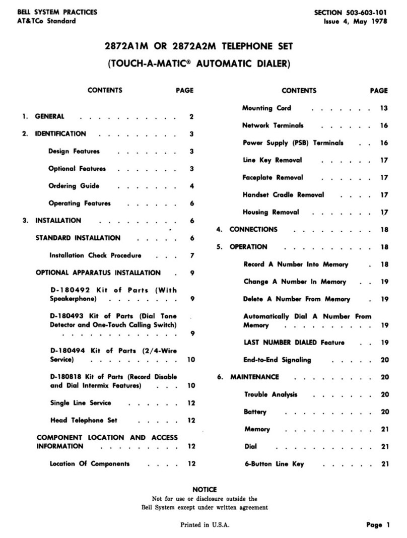
Bell System Practices TOUCH-A-MATIC 2872A 1M User manual

Bell System Practices
Bell System Practices Plant Series Service manual
Bell System Practices
Bell System Practices 2636CA Assembly instructions
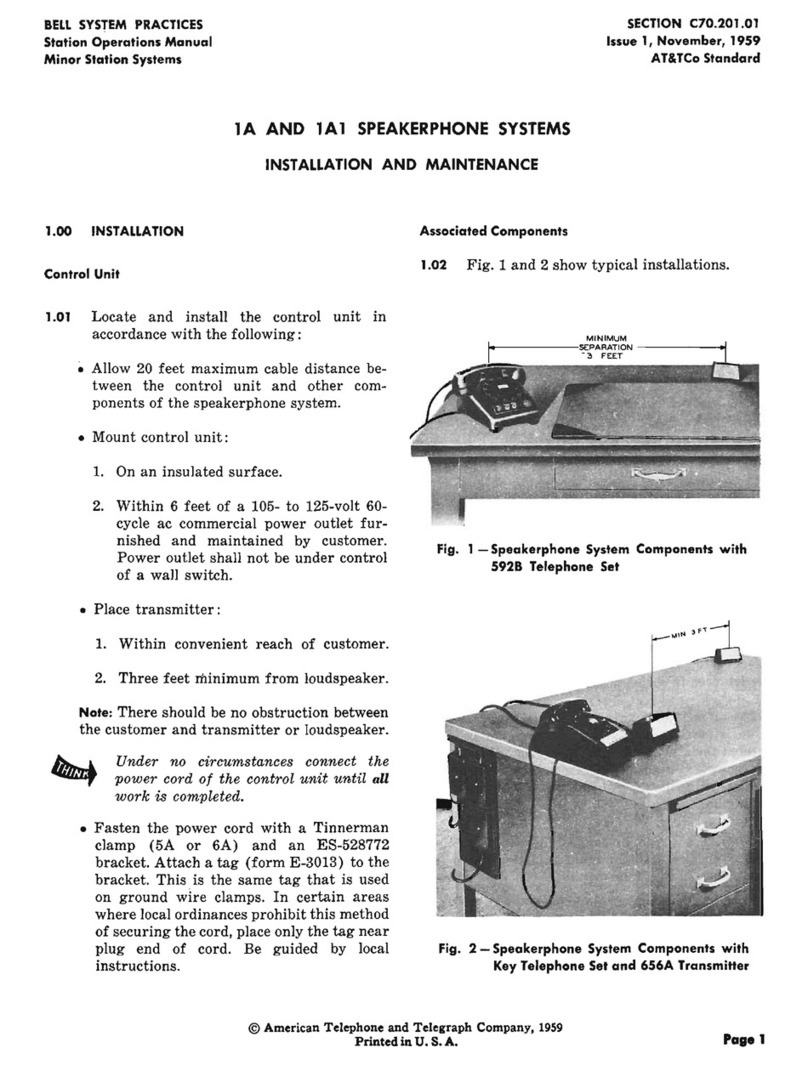
Bell System Practices
Bell System Practices 1A Instruction Manual
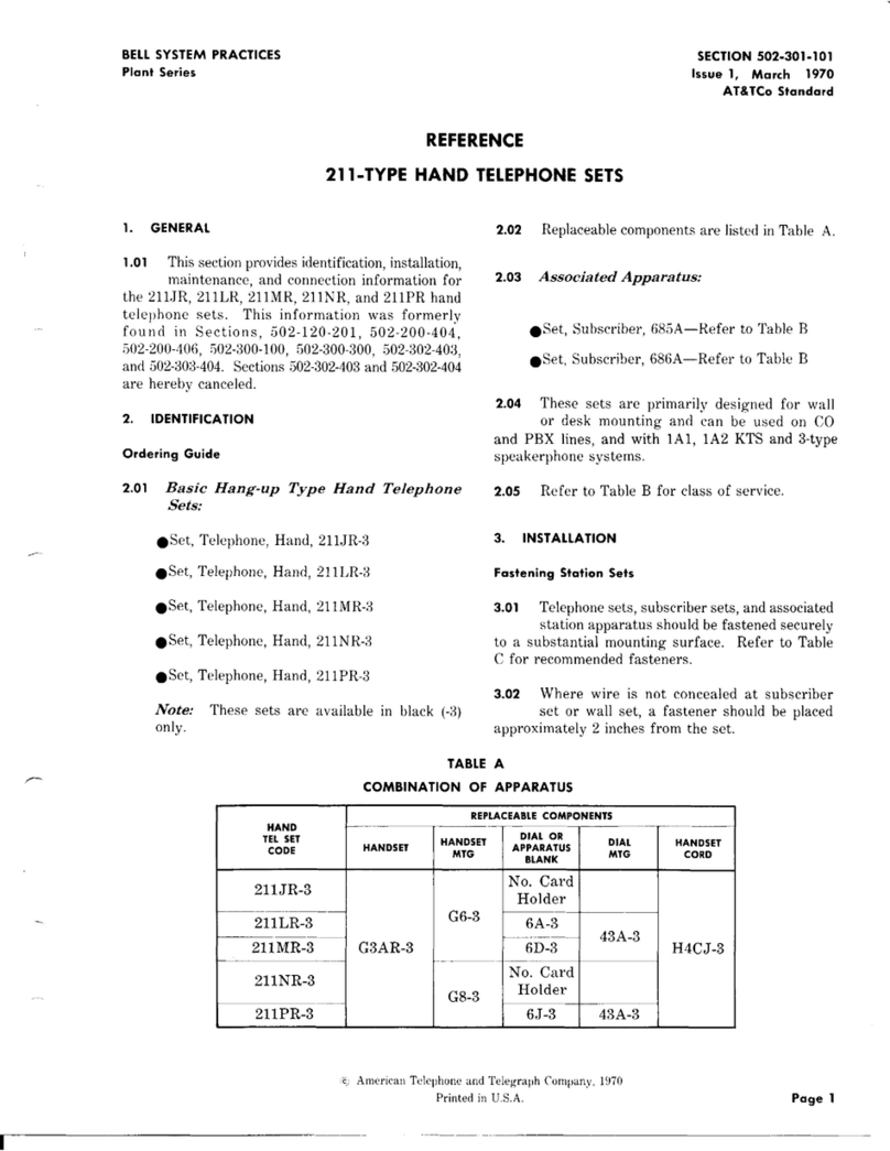
Bell System Practices
Bell System Practices 200 Series Service manual
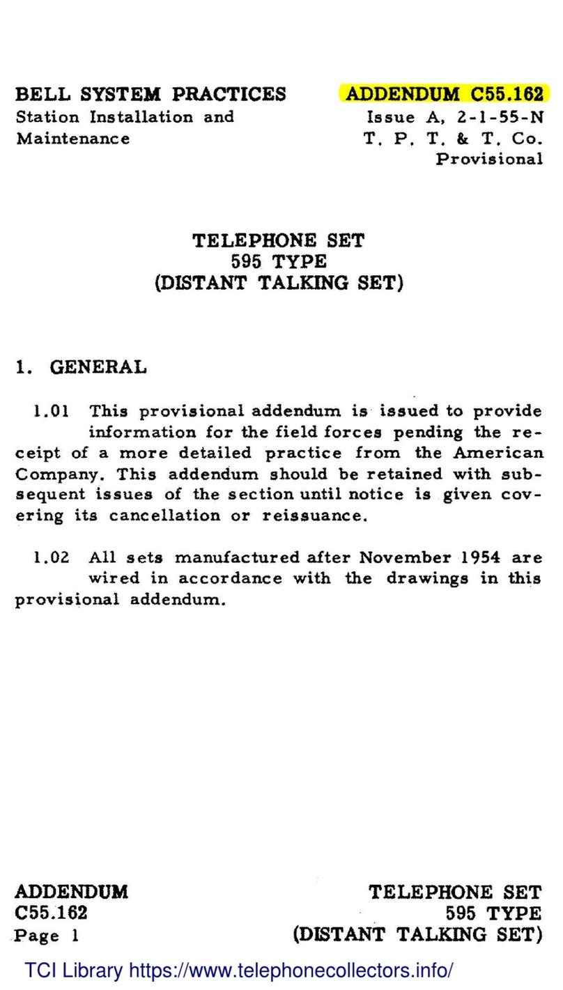
Bell System Practices
Bell System Practices 595 Installation and operating instructions
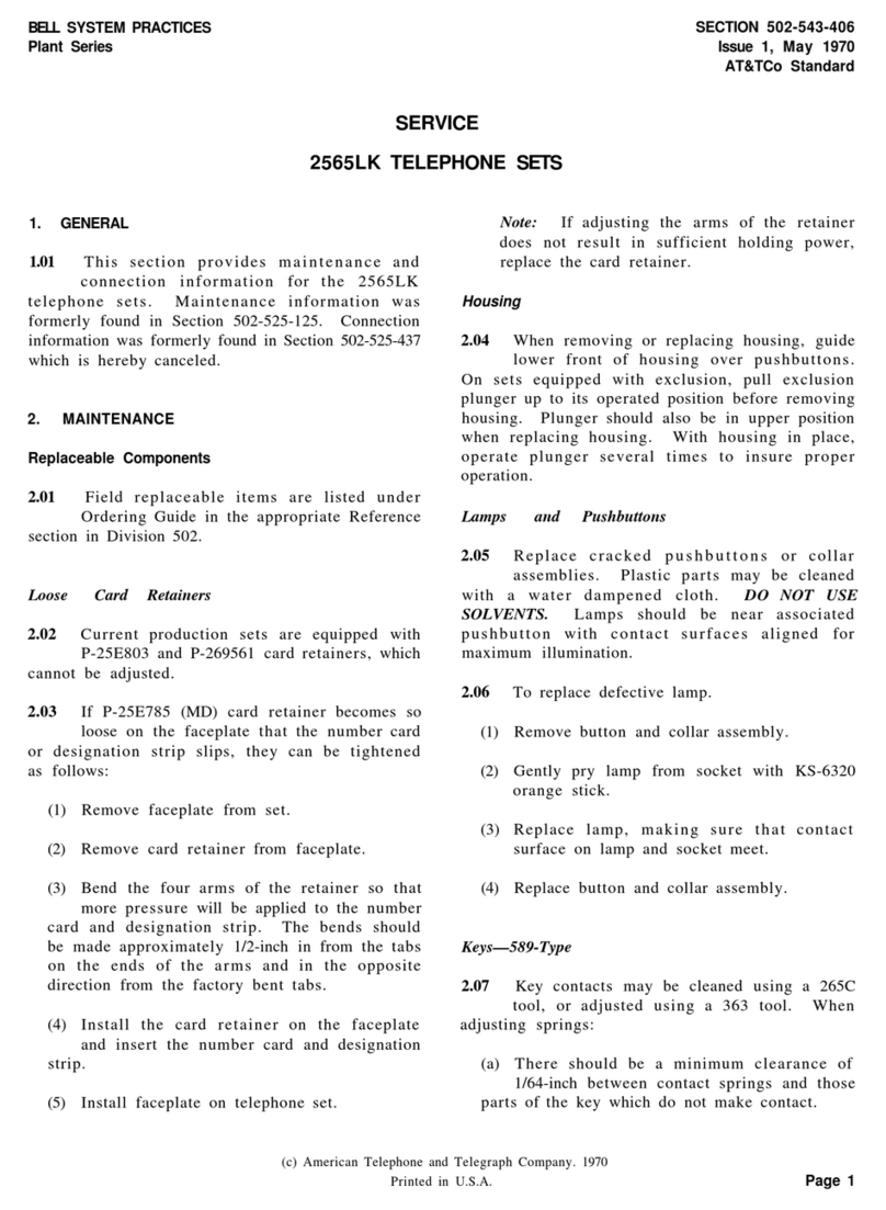
Bell System Practices
Bell System Practices Plant Series Assembly instructions
Bell System Practices
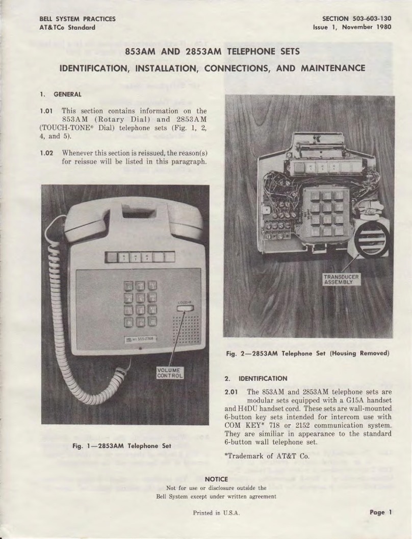
Bell System Practices 853AM Guide
Bell System Practices
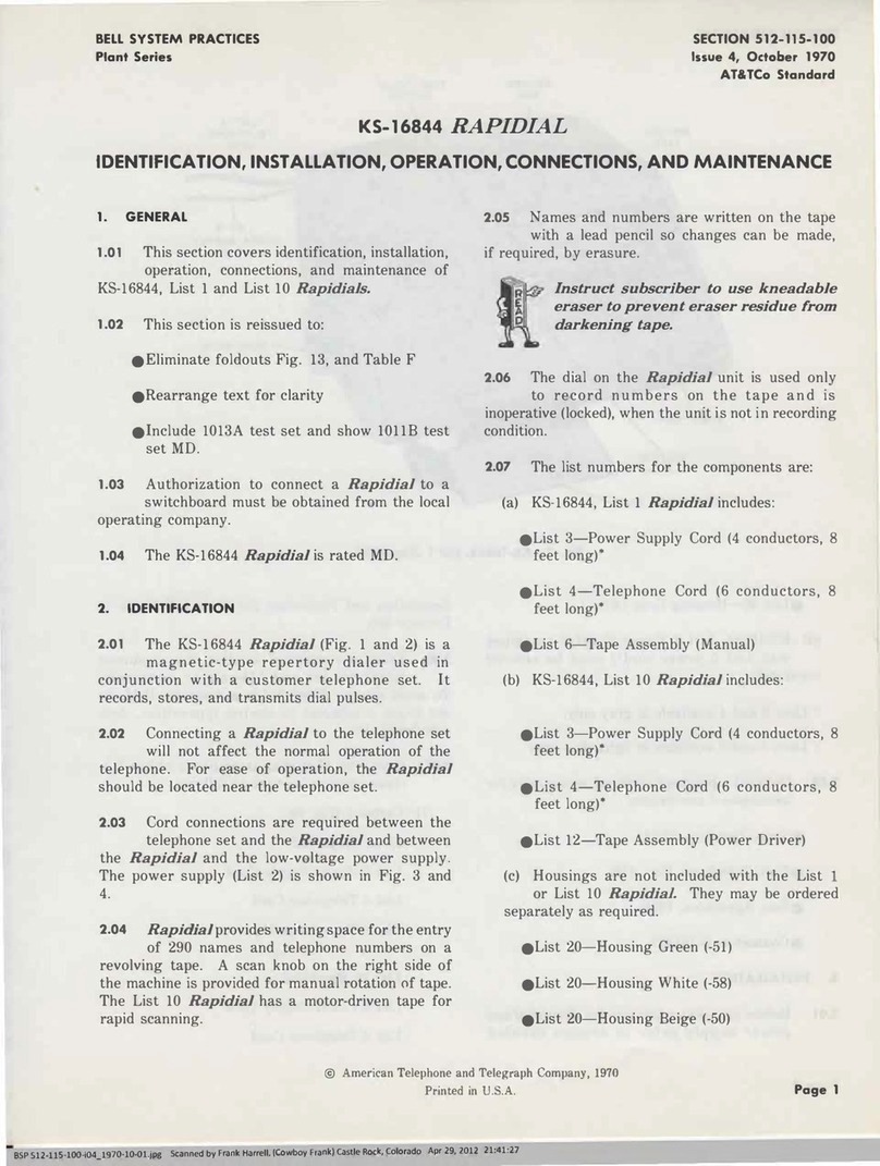
Bell System Practices Plant Series Installation and operating instructions

Bell System Practices
Bell System Practices Plant Series Service manual
Bell System Practices
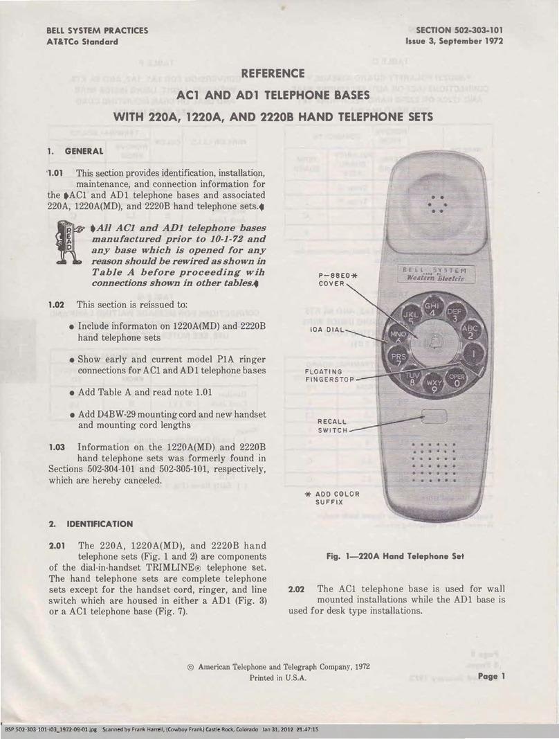
Bell System Practices AC1 Service manual
Bell System Practices
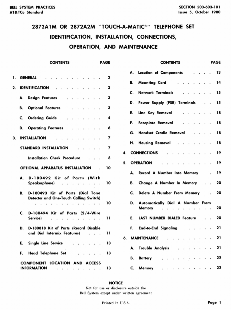
Bell System Practices TOUCH-A-MATIC 2872A1M Instruction manual
Bell System Practices
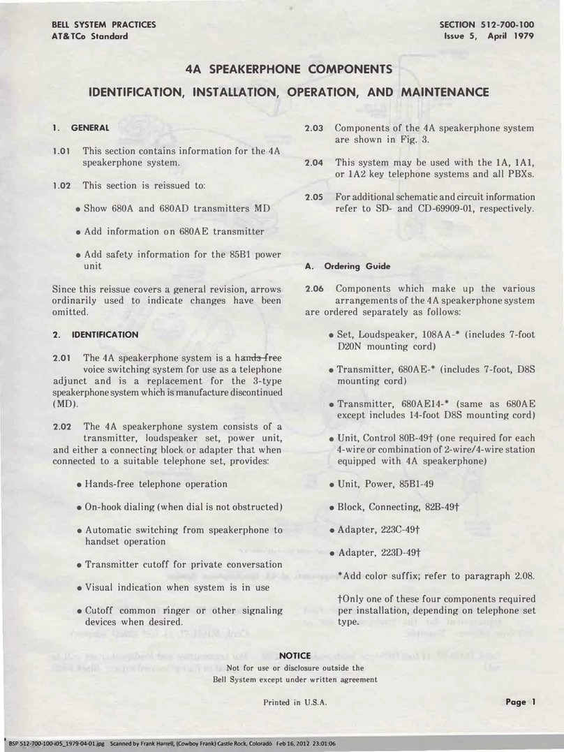
Bell System Practices 4A SPEAKERPHONE Owner's manual
Bell System Practices
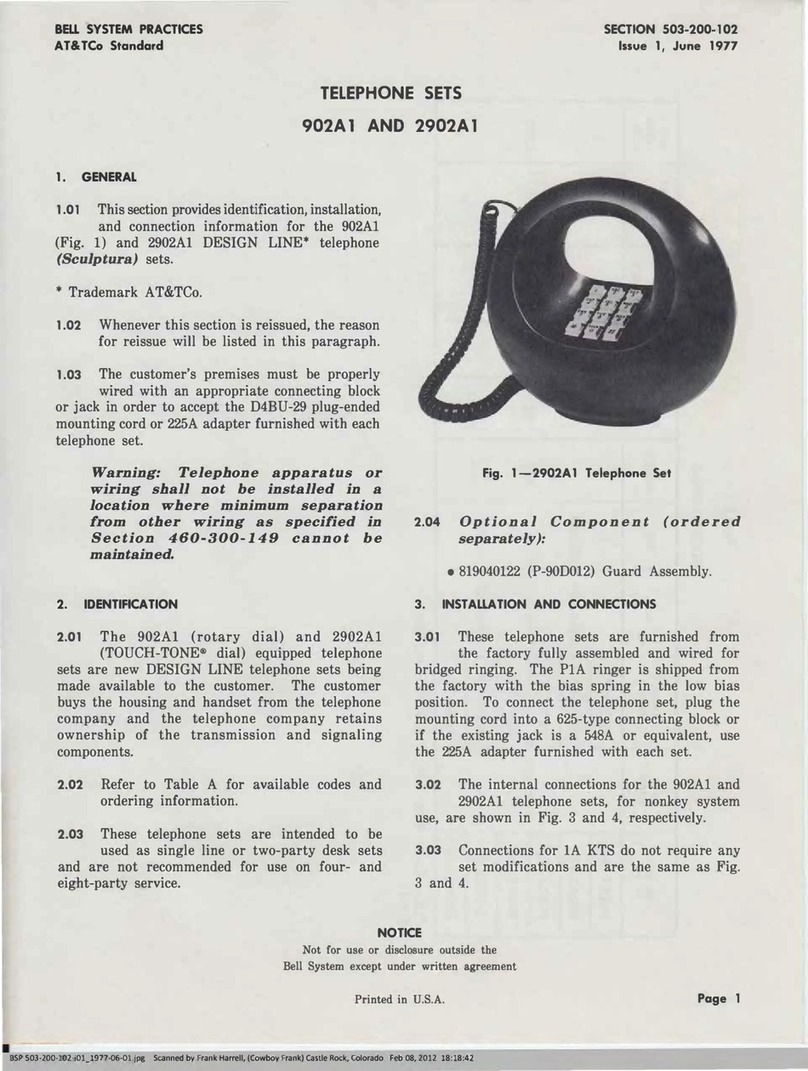
Bell System Practices 902A1 User manual
Bell System Practices
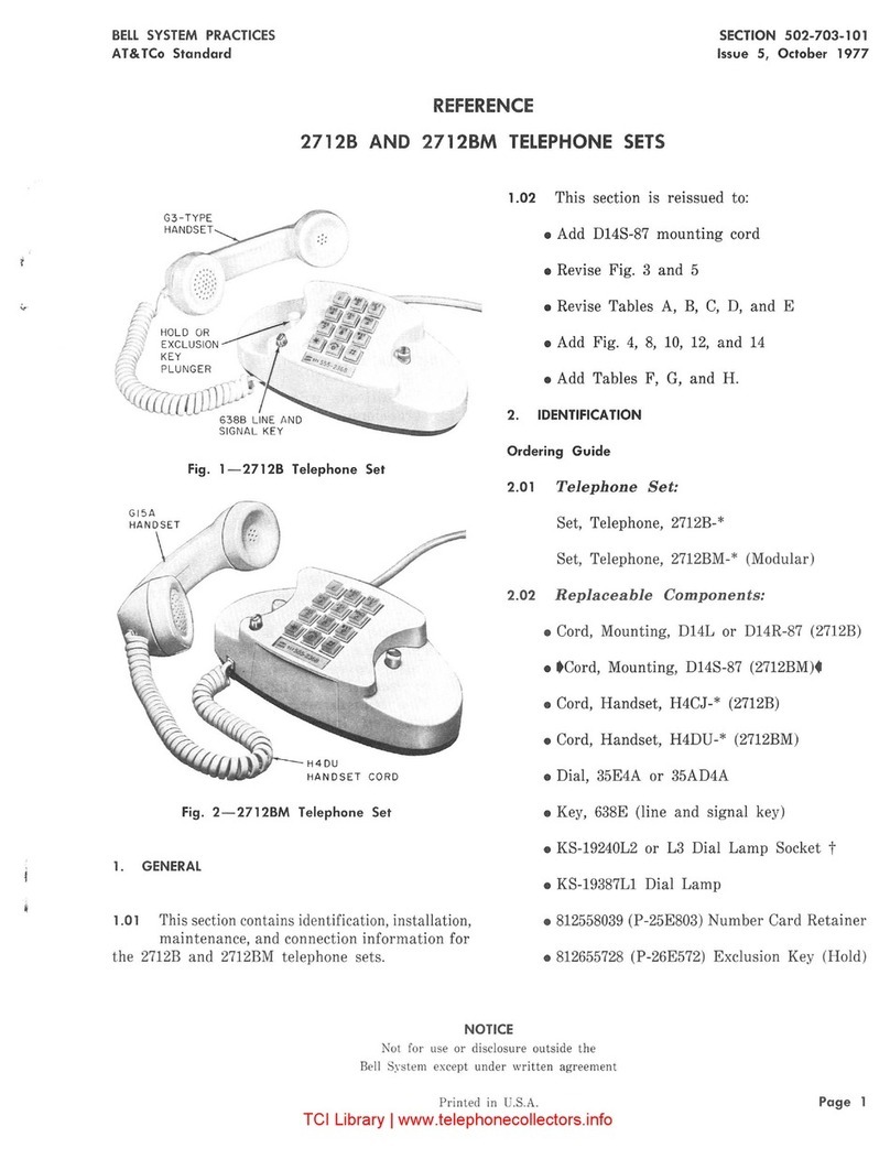
Bell System Practices 2712B Service manual
Bell System Practices
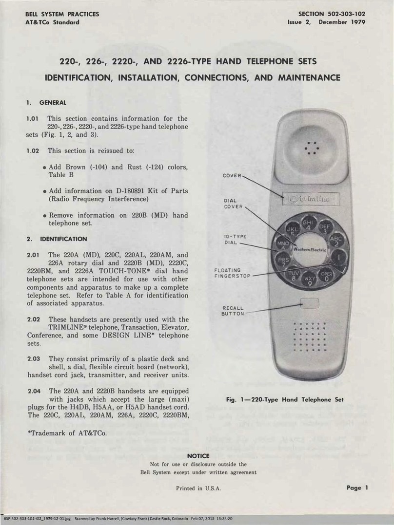
Bell System Practices 220 Guide
Bell System Practices
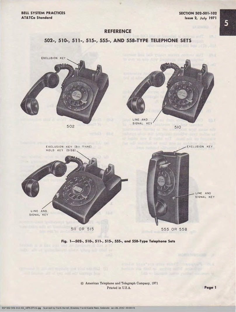
Bell System Practices AT&T 502 Service manual
Bell System Practices
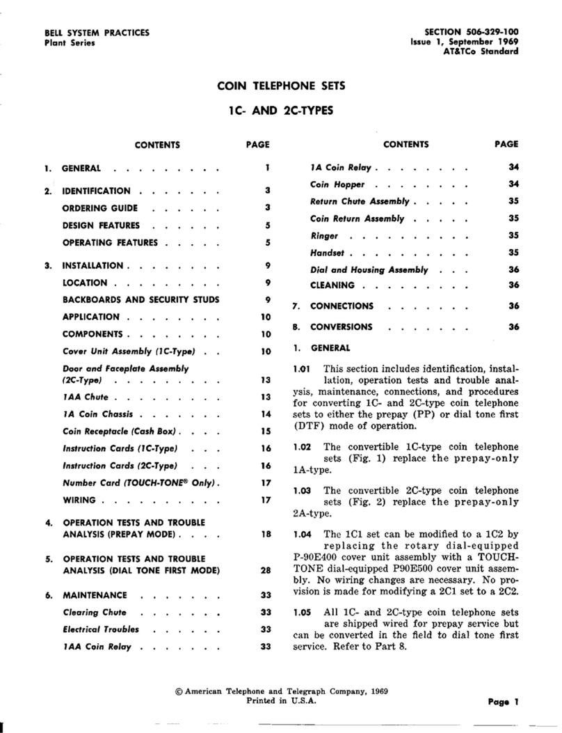
Bell System Practices 1C User manual
Bell System Practices
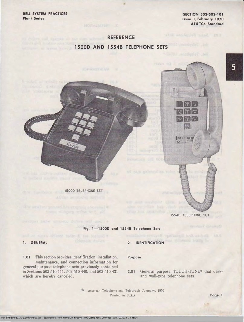
Bell System Practices 1500D Service manual
Bell System Practices
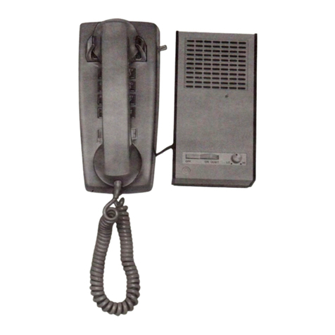
Bell System Practices TELEHELPER Instruction manual


