Bell System 220A Instruction Manual

BELLSYSTEM PRACTICES SECTION 502-320-100
Plant Series Issue 4, November 1967
AT&TCo Standard
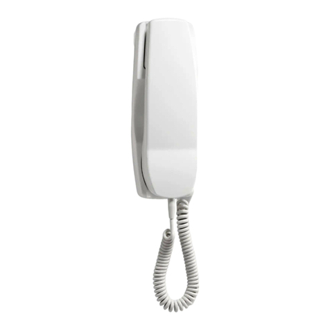
HAND TELEPHONE SET--220A AND 1220A
IDENTIFICATION, INSTALLATION, MAINTENANCE, AND CONNECTIONS
1. GENERAL • Dial, 80B2A (1220A)
1.01 This section is reissued to: • Form, E5002A (number card)
• Add piece part information for dial face • Lamp, 53A
cards (1220A only)
• Lamp, 53B
• Add piece part number for dial hub cover
(220A only) • Network, 854A (220A)
• Add ivory (-50) and red (-53) to color list
(Table A) • Network, 861A (1220A)
• Add information on 53A dial lamp • P-22F5* Card (1220A only)
• Show LB1 receiver unit replaces LA1 • P-25E803, Number Card Retainer
eRemove reference to 2160A dial lamp •P-28E320, Light Seal
transformer
• P-88E0* Cover (220A only)
Since this reissue covers a general revision, arrows
ordinarily used to indicate changes have been
omitted. • Receiver Unit, LA1 (early models)
2.IDENTIFICATION • Receiver Unit, LB1 (current models)
2.01 The 220A and 1220A hand telephone sets • Transmitter Unit, T1
(Fig. 1 and 2) are dial-in-handset type
telephone sets. These sets are complete telephones
except for the ringer and line switch which are (b) Associated ApparatusorEquipment (order
housed in a telephone base. separately)
ORDERING GUIDE •ACI-* Telephone Base
Set, Telephone, Hand 220A-* • ADI-* Telephone Base
Set, Telephone,Hand 1220A-*
02012A Transformer (for other suitable
(a) Replaceable Components transformers, see section on transformers)
• Cord, Handset H4DB-* • Cord, Handset H4DB
• Cord, Handset H5AA-* • Cord, Handset H5AA (required for tip party
• Dial,10A (220A) identification)
© American Telephone and Telegraph Company, 1967
Printed in U.S.A. Page I
SECTION 502o320-100
(c) Customer Instruction Booklet
• GN-2426(220A)
• GN-2433 (1220A)
* Refer to Table A for color selection.
/o ®
o •
@ •
••
P - 8 8EO -.X-- _{ CARD_
COVER ................ 80B2A
IOA
FLOATING RECALL SWIT
FINGERSTOP
g Ib ! I o o _/
RECALL *• • t, _ 2t
SWITCH _ _ SEE TABLE A • • • Q, • L
! :: 1::
".:::2: '\
...... i
-_ADDCOLORSUFEIX
'Fig.2--1220A Hand Telephone Set
Fig. 1--220A Hand Telephone Set
Page 2

ISS 4, SECTION 502-320-100
COLOR
TABLEA
COLOR SELECTION AND PIECEPART INFORMATION*
HAND TELEPHONE SET,
DIAL HUB COVERtAND DIAL FACE CARD
HANDSET CORD (1220A ONLY)
STANDARD COLOR SUFFIX COLOR PIECEPARTNO
Black --03 Slate P-22F570
Cinnamon
Ivory --50 Brown P-22F571
Dark
Green --51 Jade Gray P-22F5..72
Red --53 Burgundy P-22F573
Yellow --56 Gold 'P-22F574
White --58 Slate P-22F570
Rose Pink --59 Rose P-22F575
Lt. Beige --60 Sandalwood P-22F576
Lt. Gray --61 Slate P-22F570
Aqua Blue --62 Peacock Blue P-22F577
Turquoise --64 Turquoise Green P-22F578
* Refer to Section 500-120-100 for promoted colors
t 220A hand telephone set only
3.INSTALLATION (b) Installing
(a) Planning(1) Connect the 220A or 1220A hand telephone
set to a telephoile base by plugging the
5-1/2 foot H4DB cord (Fig. 3) into the jacks
• SaCety for yourself, customer, and maintenance on each component.
1__rsonnel.
(2) If tip party identification is required, an
• Location--desk, table, wall, etc. H5AA cord must be used. Check under
number card window to see that screw used
in tip party identification switch is tightened
• Space requirements, down (early models, Fig. 4). The absence of
a screw or screw hole in the identification
switch position (Fig. 5) indicates that the
• Distance between associated equipment or connection has been made in the network at
apparatus, the factory. The H4DB and H5AA handset
cords are also available in 9- and 13-foot
• General appearance of installation, lengths.
Page 3

SECTION 502-320-100
If it is necessary to use an H5AA cord
for other than tip party identification _.,,
service, disconnect the (BL) ringer lead
from B terminal onthe terminal board
in the base, insulate and store.i
(3) The 220Aand 1220Ahand telephone set
is factory equipped with a 53B diallamp;
power for lamp is supplied by a 2012A RECALL
TRANSMITTER SWITCH
transformer. DO NOT USE 2012B cup CONTACTS
TRA NSFORMER.
The illumination of the dial diminishes
with increased cord lengths.In
installations where the illumination
is considered inadequate,the 53B
lamp may be replaced by a 53A,
provided the lamp power is supplied
by a 2012A transformer and the IOADIAL
combined lengths of mounting and
handset cords are not less than 14-1/2 _,:
feet.Refer to Fig.6 for dial lamp
replacement. _:
TIP PARTY
'?,TCH
(ON EARLY
MC3DELS
DIAL LIGHT
P
I
'_o i__=_I/TELEPHONE
[, l.,!,*f BASE PLUG
- _$, [SQUARE GROMMET) ]o RECEIVER
"x HAND TELEPHONE
SET PLUG
(TAPERED GROMMET)
Fig.3--H4DB Cord Fig.4--854A Network
Page 4

ISS 4, SECTION 502-320-100
TIP PARTY
IDENT SWITCH
LOCATION
, q _ (EARLY MODEL)
i "* /
SCREWS
DIAL
L
FORM NO.
E-5OO2A
Fig.5--220A Hand Telephone Set, Number Card Removed
(4) Install Form E5002A (number card) in tone at conclusion of dialing a nutnber,he may
space provided above the dial. Use depress the recall switch for a few seconds; then
KS-16750L2 releaser to remove number card release. Dial tone will again be heard. This is
holder. Replace holder by inserting one end done in place of depressing line switch plunger
in the recess. Put light pressure on the on the telephone base.
other end to cause a slight outward bow and
snap into recess. Caution: If the recall switch is depressed
during conversation or dialing, central
office equipment may be disconnected.
INSTRUCTING THECUSTOMER(b) "'Floating"Finger Stop (220A only)
(a)Recall Switch (Fig.1 and 2): Point out
recall switch and explain advantages of •Demonstrate finger stop by dialing digit
switch. Example: If a person receives busy "1". Then depress recall switch.
Page 5

SECTION 502-320-100
• To prevent dialing errors, every digit dialed 4.02 Interior views of 220A and 1220A hand
requires rotation of fingerwheel until finger telephone sets are shown in Fig. 9 and 10.
is stopped. Refer to Fig. 5 to remove housing screws concealed
under the number card holder and dial light seal.
(c) AC1 Telephone Base: Show customer how
to place 220A or 1220A hand telephone set 5.CONNECTION INDEX
in waiting position as shown in Fig. 7.
Fig. 11 220A Hand Telephone Set Wiring
4. MAINTENANCE Diagram
4.O1 Limited field maintenance of the 220A and Fig. 12 1220A Hand Telephone Set Wiring
1220A hand telephone set is recommended. Diagram
Transmission trouble,defective dial or network
should result in replacing complete handset. Replace
defective dial .lamp and handset cord as follows:
(a) Dial Lamp: To replace a defective dial W'.t:,'iTING
lamp (Fig. 6),use 553A tool. To gain access .:
to the lamp, remove number card retainer, ""
number card, and light-seal plate.
(b) Handset Cor.d_ To replace a plug ended ,_ ;
handset cord (Fig.. 8),use a KS-16750L2 _::_ ,_
releaser. Insert tool in spaceprovided and apply
pressure agai_t spring clip toward body of _'_ o : "'
plug. When spring clip has been depressed,
pull plug out of jack.
Fig.7--220A Hand Telephone Set in Waiting Position
Fig.6--Replacing Dial Lamp on AC1 Telephone Base
Page 6

ISS 4, SECTION 502-320-100
=RESSURE
APP_ ED
TOWARD PLUG
/
/
/
J
f
J
J
,J
Fig. 8--Removing Cord From 220A Hand Telephone Set
Page 7

SECTION 502-320-100
r_ ' _:_...... ;;_ _ _," • _,• " o_'--:"............ ,_'_--
)/•
.o ,_. ._::_ •
FLEXIBLE......._" ....
PRINTED MOUNTING SCREW
WIRING DIAL LIGHT BLOCK
CORD DIAL IDA DIAL RECEIVER CUP
JACK CONNECTIONS CONNECTIONS
Fig. 9--Interior of 220A Hand Telephone Set
Page 8

ISS 4, SECTION 502-320-100
_80B2A DIAL
\z_56_34/
TOUCH-TONE DIAL
CONNECTIONS
Fig. 10--Interior of 1220A Hand Telephone Set
Page 9

SECTION 502-320-100
::i::!::::: 854A NETWORK
H4DBORHSAA iiiiiii!iii
CORDi;ii;i;iiil
:::::ii:i
i_:ili:i:i
:..:::
cY) [w] i!ii;ii:;i
< ">'>I []_) DIAL
iiiiiiiiii LIGHT
(BK) [BK]
<......... '_ 2 >_ DIAL PULSE
iiiii[ilil C O N TA C TS
iLiiii,i f,----_ o ]
(G) [G] i_iiiiiiii;
:::::2:::
iiii!iiii!: RECALL
ililiiiii SWITCH
iiiiiiiiii: C0 NTA CTS
!iii:i)::2
iiiiiii!il;
.:.::::::
.::.::.::
::::::::::
ii#iii;:
::::::::::
:::::::::::
::::::::::.
i!ili#
iiiiijii!i
ilililiiii:
::::::::::
::x..::::
!ii!i!i!!!
i!!!i!i!i! i
izi_i_ii!ii
i!iiiilili RCVR
::::::::::
::::::::::
:::.::::::
iiiiiiiii! TRMTR
iiiiii!i!i
i_i!i!i!iil
!i!!!i!!ii
_ili!i;!!i
x<.:+:
!:!8_:!:
::::::::::
!ii!!ii_!_:
::::::::::
::::::::::
..........
iiiii!#:
.:::::::::
!_iiiii_ili
:?:!:!8_:
i:!:i:_:i:i
iSi:i:!:!
::::::::::.
8i8!:!:
..........
iiiiiiiiill
iii#ii!
:.:::.::
iiiii!_!i!i
::::.:::.
::::::::::
::::::.:::
:::::::::::
::.:..::::
::::::::: i
::::::::::
:ii}ii:!i:
(R) [R] ii!;ii_ .> 3>o
<:!:i:!:!8
iiiiiii#! RECALL
)iiii!ili}i SWITCH
_i_i_i_i_i_ CONTACTS
•:::::.::i ( ) COLORCODE H4DB CORD
:!i!iiii!_:
ili!iiiiil[ ] COLOR CODE H5AA CORD
iii#i!:
°, . <...
_i#!i!!!
i:iii!i!!!
[Y] iiiiiiiiill
_-- ...............-- -->5>
:::::::.::
Fig. 11--220AHand Telephone Set--Wiring Diagram
Page 10

ISS 4, SECTION 502-320-100
:::::::::::::::::;::
H4DB!i!:!iiiil B61A NETWORK iii_i_i_il 80B2A DIAL
OR iiiiiiiiil _!i_i_
HSAA iiiiiiili_ ii!i!iiiii
CORD !iiiiiiiil !iii!iiiil
iiiiiiiii_ !!;iii!;!!
:::::::::
::::::::::
:::::::::: LIGHT ............... .......,.
<+:.::.,....,..
:::::::::_iii_iii:
(BK) [BK] _;iiiiiiii_ iiiiiiiiil
:::::::::: #ilili:
!iliiiiiil RECALL ;iiiiiiill
•:::::::::: SWITCH_ii_i_i_i
.......
(+)iiiiiiiiii,
........
IIG]..........
"'' CONTACTS
::::::::: :::::::::
iiigi!i!i][ [ j:i:!:i:! @.
•.,.....-::::::5::
......... ........
!i!_!;!!i:!_!_!iEi!:
...............
::::::::: ::::::::::
.:+:.:<........._
i;i!i_i_i (w) !i_iii!i_i
!iii!iiiii
::::::::::
:iii!!!iiii RCVR _ i:i:S:i:i:
:_!_!: TRMTR ::::::::::
:::::::::: l::::::::::
_ii!iiiiiil _iiiii_i;
-::::::::: ::::::::::
:+:,:.: ::::::::::
iiiiiiiii!: _ iiiiiiiii;
}iiiiiiiii: iiiiiiiii:
......, ........
::::::::: :::::::::
::::::::: i:i:i:i:i:
:::::::::: :::::::::.
:::::::::: .....,.,.
::::::::: :::::::::
:!!::!ii!_i iiiiii!ii
:iiiiiiiii i!i!iiiii:
:::::::::: i:i:_:_:_
.......... iiiilili_
iiiiiiiiii
iiiiiiiii,i
_!i!ii!iii
........
......
:::::::::
:iiiiilili
:::.:.::::
(R) [R] i!iiiiiiii
< i:!i!!i!i>
........
i!iiiiiii RECALL
iiiiiiili SWITCH
iiiiiiiiil CONTACTS
..........
_iiiiiill
........
::::::::::
iii_ili!_i
iii:ili_il
•.-..-.-......
_i_"_ 5 >( ) COLOR CODEH4DBCORD ..-......iiiiiiiiii
_!i!iiii!! [ ] COLOR CODE HSAA CORD iiiiiiiiii
Fig. 12--1220A Hand Telephone Set--Wiring Diagram
Page11
11 Pages
This manual suits for next models
1
Table of contents
Other Bell System Telephone manuals

Bell System
Bell System 500LM/MM Assembly instructions

Bell System
Bell System 500A Service manual

Bell System
Bell System 5100AM User manual

Bell System
Bell System 630A Assembly instructions

Bell System
Bell System Bellcall User manual

Bell System
Bell System 701B User manual

Bell System
Bell System 2636CA Assembly instructions