Bell System 5100AM User manual

BELL SYSTEM PRACTICES
AT &TCO Skmdad
5100AM TRANSACTION TELEPHONE SET BASE
SECTION 502-323-401
Issue 1, August 1976
WITH 220- OR 2220-TYPE
1. GENERAL
1.01 This section contains identification, installation,
connection, and maintenance information for
the Transaction II telephone set which consists of
a51OOAM base, faceplate and a220- or 2220-type
hand telephone set. For detailed information on
components, refer to CD- and SD-69926-01.
1.02 Whenever this section is reissued, the reason
for reissue will be listed in this paragraph.
1.03 For use behind akey system, Aand Al
leads are provided by the black (BK) and
yellow (Y) leads, respectively, in the mounting cord.
If common audible ringing is to be provided, a
separate ringer is required.
1.04 For additional information on the Transaction
telephone system, refer to Technical Reference,
PUB 41804, titled “Switched Network Transaction
Telephone System Interfacing With Audio Response
Units.”
2. IDENTIFICATION
2.o1 The 51OOAMTransaction telephone set base,
equipped with a220- or 2220-type hand
tele~hone set (Fig. 1) provides the standard features
of a
set. single line rotary or TOUCH-TONE” telephone
Note: If the customer elects to have the
dial of the hand telephone set made inoperable
(as covered by 3.33) then it can only provide
incoming service and card dialer service.
It can also automatically dial and electronically
transmit information read from amagnetic stripe
on acredit card, or keyed on a15-button manual
entry pad (Fig. 1), to adata center for immediate
credit authorization, check verification, or inventory
control. In addition, it is possible for atransaction
to be accomplished in ahands-free mode.
HAND TELEPHONE SET
2.02 Design Features:
●
●
●
●
●
●
●
●
●
b
2.03
●
●
●
●
NOTICE
Modular type
Magnetic stripe card reader (ABA Track 2)
Automatic dialer
Click-disc type 15-button manual entry pad
Operating instruction lamps (light emitting
diodes [LED])
Hands-free operation
Electronic switchhook and call progress
sounder
Volume control for call progress sounder
Green/yellow approval or referral lamps
(LED)
Data receiver and an 8-digit alpha/numeric
display.
optional Features:
TT/DP (TOUCH-TONE/DIAL PULSE) option
allows use of button pad and card reader
into arotary or aTOUCH-TONE dial office
15-button manual entry pad may be locked
inoperable for outgoing calls
TOUCH-TONE signal output level of set
from button pad or card operation may be
changed to compensate for loop loss
An auxiliary manual entry pad (5000A-50
dial) may be connected to allow use of a
Personal Identification Number (PIN).
Not for use or disclosure outside the
Bell System except under written agreement
Printed in U.S.A. Page 1

SECTION 502-323-401
8-DIGIT
CARD READER DISPLAY
\ICARD IN
STORAGE SLOT
/
..
.J
.“. ‘
220-OR 2220- a=
TYPE HAND
TELEPHONE SET. ‘i ‘
ON .50FF
BUTTONS
MANUAL
ENTRY PAD<
D4Bu-29/
MOUNTING CORD
-UPPER
K
HOUSING
VOLUME CONTROL
FOR CALL PROGRESS
d
SOUNDER
‘GREENI3 YELLOW
rIRESPONSE LAMPS
/
LOWER HOUSING
Fig. 1—51OOAM Transaction II Telephone Set Base Equipped With 220- or 2220-Type Hand Telephone Set
2.04 The 51OOAM Transaction II telephone set
base is available in Ivory (-50) only. These
bases will be shipped with adisposable protective
faceplate, so it is necessary to order the proper
faceplate separately (Table A).
2.05 Ordering Guide: (b)
(a) The 51OOAM Transaction II telephone set
base consists of all the necessary circuitry
including power unit and card reader and should ●
be ordered as:
●Base, Telephone Set, 51OOAM (includes the ●
following):
Cord, Handset, H4DU-50 (c)
Cord, Mounting, D4BU-29 (7 foot provided,
840996003 Test Card B(additional cards
may be ordered)
Subscriber Instruction Booklet (SIB-2482C)
One of the following is also required and
must be ordered separately
Set, Telephone, Hand, 220A-50 (Rotary dial)
Set, Telephone, Hand, 2220B-50 (TOUCH-TONE
dial)
If the auxiliary manual entry pad is to be
used, it will be necessary to order the
14- or 25-foot available) D-180687 Kit of Parts (which includes the 5000A-50
dial) and also an appropriate faceplate (Table
Adapter, 227A (for handset cord) A).
Page 2

1SS 1, SECTION 502-323-401
I. CONNECT RED (R) GREEN (G) YELLOW (Y), ANO
BLACK (BK) CONDUCTORS OF STATION WIRE
ALONG WITH (R), (G), (Y), AND (BK) JACK
LEADS OF 625C TO TERMINALS R, G,Y, AND
B, RESPECTIVELY, OF 42A CONNECTING BLOCK
2. PLACE 625C ONTO 42A AND SECURE
3. PLUG ONE END OF D4BU CORD INTO JACK OF
625C AND OTHER END INTO JACK IN BASE
OF TELEPHONE SET kSTATION
WIRE
‘42A
CONNECTING
BLOCK
CONNECTING
NOTE:
3. INSTALLATION
3.o1 Terminate the
block suitable
(SEE NOTE)
PLUG INTO BASE
OF TELEPHONE SET
D4BU
\
A625A CONNECTING BLOCK
MOJJNTING CONSISTS OF A625C AND
CORO A42A CONNECTING BLOCK
Fig. 2—installation of 625A Connecting Block
modular connecting blocks or adapters, refer to
Section 503-100-100.
local loop into aconnecting
for the D4BU-29 mounting Warning: Any magnetic stripe card
cord, but do not connect the mounting cord at this may have its encoding destroyed if
time. The use of a625-type connecting block (Fig. the card is carried or stored near a
2) is recommended. For information on other magnet or magnetized object.
Page 3

ISECTION 502-323-401
TABLE A
TRANSACTION II
FACEPLATE ORDERING GUIDE
[
FACEPLATE
TEL SET CODE LETTERING INTENDED USE
NUMBER
138C1-* Blank Without
51OOAM
Tel Set
Base
138C5-* Standard Auxiliary Manual
Instructions Entry Pad
*Add appropriate color suffix from Table B.
TABLE B
coLoR ORDERING GUIDE (SEE NOTE)
HAND
TEL FACEPLATES
SET
ISUFFIX iCOLOR ISUFFIX ICOLOR I
-1oo Avocado
-108 Teak
-109 Walnut
-50 Ivory -111 Gold
-112 Orange
-113 Brown
-114 Red
-115 Blue
-118 Black
Note; The 51OOAM telephone set base is avail-
able in Ivory only and the hand telephone set
should also be Ivory. The faceplate must be
ordered separately.
3.02 Connect the TRIMLINE@ handset to the
51OOAMtelephone set base using the handset
cord and adapter. (A 616P jack is provided on
the front of the base.)
3.03 Insure that there is an available 110-volt,
3-wire AC receptacle, not controlled by a
switch, within reach of the 6-foot power cord.
A3-wire outlet is required for safety
K
andproper operationof the set. Third
!/ conductor must be grounded. If third
wire is not provided and grounded,
the resistance of the set to
electrostatic damage is 10wered
and the probability of failure is
greatly increased.
3.o4 To intall 138-type faceplate, proceed as
follows:
(1) Remove disposable faceplate by lifting at
the midpoints of the left and right edges.
When faceplate is bowed slightly, the locking
tabs at top and bottom will release.
(2) Install new faceplate by inserting bottom
tab into housing and slightly bowing the
faceplate enough to insert upper tabs into slots
of housing.
Note: If auxiliary manual entry pad is to
be installed, do not install faceplate at this
time.
TRANSMISSION MEASUREMENTS (INSERTION LOSS)
3.05 The signal output level of the TOUCH-TONE
frequencies transmitted by the Transaction
11 set must be adjusted to match the loop being
used. Make aloop insertion loss measurement
using a23D Transmission Measuring Set, or the
equivalent, and a900 ohm termination. Dial the
milliwatt supply (1000 Hz) of the serving central
office, read and record the loss of the loop.
Page 4

3.06 It is recommended that at this time the set
should be opened up (3.07) and all option
plugs on main printed wiring board (PWB) and
control board checked to insure that they are in
their “when shipped” positions as shown by Tables
Cand Dor Fig. 4and 5. Check wiring terminations
and if any loose connections are found, reterminate
per Fig. 11.
3.07
(1)
(2)
3).
(3)
any
(4)
3.08
(3.05)
(1)
(2)
To open set in order to access option plugs
and/or terminals proceed as follows:
Disconnect power plug from AC outlet, if
connected.
Invert set and loosen the two captive screws
holding the upper housing and chassis (Fig.
Lay the upper housing and chassis to the
right, as shown by Fig. 6, without disconnecting
cables.
To reassemble, reverse procedure.
Set the TOUCH-TONE signal output level
for the actual measured loss of the loop
as follows:
Place the options on their proper positions.
See Fig. 4and Table C.
If the loss of the loop is 3.9 dB, or less,
resistors R2 and R3 on the control board
should be placed in the circuit. This is done
by moving the option pins from B-C to A-B as
shown by Fig. 5.
(3) If 10SS of 100P exceeds 12 dB the quality of
the service may be impaired. Defer, according
to local procedures, until an acceptable loop is
made available.
3.09
block.
3.10
Connect the set to the telephone line by
inserting the mounting cord into the connecting
Remove the gum-backed “OPTIONS” sticker
which is pa~ked with the base and attach
it to the bottom of the base near the front. If
the service order does not call for the implementation
of any options (Dial Pulse, Lockout, or disconnection
of the ringer) at this time, reassemble set and
proceed to 3.12.
1SS 1, SECTION 502-323-401
Note: If the order calls for making dial of
hand telephone set inoperable, do not disable
dial until all testing is completed.
OPTIONS
3.11 If the service order specifies that the Dial
Pulse and/or Lockout options be activated,
or that ringer be disconnected, access the main
PWB (3.07) and proceed as follows:
(a) If both Dial Pulse and Lockout options are
called for:
(1)
(2)
(3)
Place TT/DP option plug for DP per Table
D.
Place upper housing and chassis back on
set and reconnect AC power cord.
Go off-hook and, using manual entry pad,
dial any test number and verify that the
call is completed. This tests the dial pulse
feature.
(4) Disconnect power cord, lay upper housing
and chassis aside, and move Lockout
option plug to lockout position per Table D.
(5) Reassemble set and reconnect AC power
cord.
(6) Test lockout by going off-hook and
depressing any button on manual entry
pad to verify absence of TOUCH-TONE
frequency signals.
(b) If
(1)
(C) If
(1)
(2)
(3)
pad
only Dial Pulse option is specified:
Proceed as in (a) Steps (l), (2), (3) and
(5).
only Lockout option is specified:
Move Lockout option plug per Table D.
Reassemble set and reconnect AC power
cord.
Test lockout by going off-hook and
depressing any button on manual entry
to verify absence of TOUCH-TONE
frequency signals.
Page 5

SECTION 502-323-401
TABLE C
ADJUSTMENT OF TOUCH-TONE OUTPUT LEVEL (NOTE)
OPTION PLUG POSITIONS
WIRING ON CONTROL BOARD NOMINAL
oUTPUT
LOOp oN MAIN PWB RESISTOR -R2$ RESISTOR -R3$
LOSS IN LEVEL
DBs REMOVE CONNECT REMOVE CONNECT IN DBM
R-34 R-36 R-36 FROM TO FROM TO
E31-E32 E28-E29 B-C~ A-B B-C? A-B -13.5
() to 1.9* E33-E34
E30-E31 E28-E29 B-C~ A-B B-C~ A-B -11.5
2.0 to 3.9* E34-E35
E34-E35T E30-E31-t E27-E28T --9.5
4.0 to 5.9
E30-E31 -7.5
6.0 to 7.9 E34-E35 E28-E29 -
E31-E32 E27-E28 --5.5
8.0 to 10.4 E34-E35
E31-E32 E28-E29 --3.0
10.5 to 12 E34-E35
*If lmm IOSS is 3.9 dB or less, resistors R2 and R3 should be connected into the circuit as shown.
TPlug positions when shipped from factov.
$Designations are not on board, see Fig. 5.
Note: See Fig. 4for location of option plugs on main PWB.
See Fig. 5for location of wiring option on control board.
TABLE D
PLACEMENT OF OPTION PLUGS (SEE NOTE)
OPTION pLUG POSITION RESULT
Key Pad E42-E43* Not locked (can dial out from key pad)
Lock E43-E44
out Locked (cannot dial out from key pad)
TT/DP E21-E22* Key pad dials in TT frequencies
Dialing E22-E23 Key pad sends out dial pulses
Power
up E39-E40* Resets terminal to ON-HOOK condition
Reset following commercial power failure.
*Option plug positions when shipped.
Note: See Fig.4for location of option plugs.
(d) To disconnect P2B ringer: Note: Indicate on the sticker on the base
of the set any options that are implemented.
(1) Remove red (R) and black (BK) ringer
leads from terminal P1 and T, respectively, 3.12 With handset on-hook, plug in power cord
on control board, insulate and store. and then go off-hook momentarily to reset
Transaction II telephone set.
(2) Reassemble set and reconnect AC power
cord.
lVote: If no lamps light when handset is
taken off hook, either AC receptacle is defective
Page 6

MOUNTINGCORO ENTRANCEFOR5000A OIAL
~~:~::’=1 \ ,
STRAIN RELIEF MOUNlING CARD
623E4
JACK>
$WTIJ:
FOR
HOLOING
UPPER
HOUSING
\
P
VOLUME
CONTROL
FOR CALI
PRoGRESS
SOUNOER
1i\ /
o0
‘b
o0
L
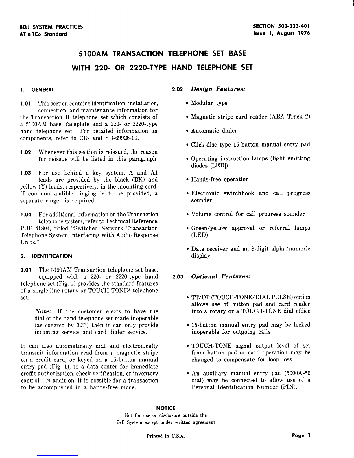
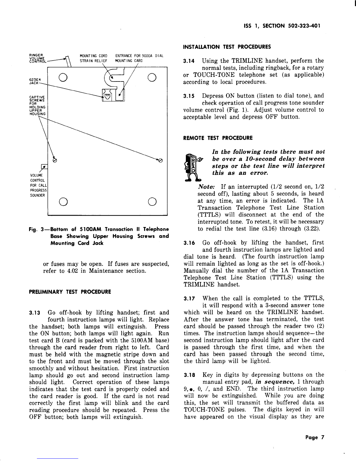
Fig. 3—Bottom of 510OAM Transaction II Telephone
Base Showing Upper Housing Screws and
Mounting Cord Jack
or fuses may be open. If fuses are suspected,
refer to 4.02 in Maintenance section.
PRELIMINARY TEST PROCEDURE
3.13 Go off-hook by lifting handset; first and
fourth instruction lamps will light. Replace
the handset; both lamps will extinguish. Press
the ON button; both lamps will light again. Run
test card B(card is packed with the 51OOAM base)
through the card reader from right to left. Card
must be held with the magnetic stripe down and
to the front and must be moved through the slot
smoothly and without hesitation. First instruction
lamp should go out and second instruction lamp
should light. Correct operation of these lamps
indicates that the test card is properly coded and
the card reader is good. If the card is not read
correctly the first lamp will blink and the card
reading procedure should be repeated. Press the
OFF button; both lamps will extinguish.
INSTALLATION TEST
1SS 1, SECTION 502-323-401
PROCEDURES
3.14 Using the TRIMLINE handset, perform the
normal tests, including ringback, for arotary
or TOUCH-TONE telephone set (as applicable)
according to local procedures.
3.15 Depress ON button (listen to dial tone), and
check operation of call progress tone sounder
volume control (Fig. 1). Adjust volume control to
acceptable level and depress OFF button.
REMOTE TEST PROCEDURE
!!lr
In the following tests there must not
be over a10-second delay between
!steps or the test line will interpret
this as an error.
3.16
Note: If an interrupted (1/2 second on, 1/2
second off), lasting about 5seconds, is heard
at any time, an error is indicated. The 1A
Transaction Telephone Test Line Station
(TTTLS) will disconnect at the end of the
interrupted tone. To retest, it will be necessary
to redial the test line (3.16) through (3.22).
Go off-hook by lifting the handset, first
and fourth instruction iamps are lighted and
dial tone is heard. (The fourth instruction lamp
will remain lighted as long as the set is off-hook.)
Manually dial the number of the 1A Transaction
Telephone Test Line Station (TTTLS) using the
TRIMLINE handset.
3.17 When the call is completed to the TTTLS,
it will respond with a3-second answer tone
which will be heard on the TRIMLINE handset.
After the answer tone has terminated, the test
card should be passed through the reader two (2)
times. The instruction lamps should sequence–the
second instruction lamp should light after the card
is passed through the first time, and when the
card has been passed through the second time,
the third lamp will be lighted.
3.18 Key in digits by depressing buttons on the
manual entry pad, in sequence, 1through
9, ●,O, /, and END. The third instruction lamp
will now be extinguished. While you are doing
this, the set will transmit the buffered data as
TOUCH-TONE pulses. The digits keyed in will
have appeared on the visual display as they are
Page 7

SECTION 502-323-401
DATA RECEIVER BOARO
/
/
~E84
E83
c1
OPTION O
E82
/$: 5;]R34
E3Z
;;:fl o 0
J
E42
E43 1
LOCKOUT
oE44
>..\IoEZ7 1
J<
EZ8 R36
oEZ9
Y)
00
.Nwl
NNP4
UJLULU
\A/
AI
rI/
MAINPuB TTIOP POUER UP RESET
NOTE: OUE TO SPACE LIMITATION ONLY THO PINS HAY BE IOENTIFIEO ON EACH OPTION PLUG
Fig. 4—Main PWB and Data Receiver
keyed and the display will clear when
is completed.
Board Showing Option Plug Locations and Plug Positions as Shipped
transmission
3.19 The green (G) response lamp will then flash
and the display shall be filled with 8’s.
3.20 Press the ERASE button. The display
should fill with decimal points, and the (G)
response lamp will continue to flash.
3.21 Key in 1, 2, 3, END. The display should
erase and the yellow (Y) lamp should light.
If the (Y) lamp does not light and the display
Page 8
shows E-O-O, reenter 1, 2, 3, END (you have 7
seconds to do this) and the (Y) lamp should light.
3.22 Press ATTN. Amuted 3-second response
is heard and the TTTLS will disconnect.
Place handset on-hook. The (Y) lamp may be
extinguished by momentarily going off-hook.
AUXILIARY MANUAL ENTRY PAD
3.23 If the auxiliary manual entry pad is
used, it should be installed at this to be
time.

SPEAKER BOARO
tlOUNTING SCREHS
AooA 1
E33 B
c c
1SS 1, SECTION 502-323-401
is bowed slightly, the locking tabs at top and
bottom will release.
Note: An 138D-type faceplate (ordered
separately, Table A) will also be required.
(2) Install 841934946 mounting plate and 651G
IIR3 RZ \)\ ~key (Fig. 8) as follows: -
/
1.~
/VI TERMINAL
‘. UNOER SPEAKER
\
L
Y
BOARO
\,-.
P
t,
1; .-
---- /
/
(S) SPADE
TIPPEO LEAO
/
‘~ \
SPEAKER BOARO CONTROL BOARO
NOTE: A, B, ANO CDESIGNATIONS ARE NOT
SHOUN ON BOARO. FOR REFERENCE ONLY
Fig. 5—Centrol Board and Speaker Board Showing
Location of R2 and R3 Option Plugs and
Terminal Y1
To install the D-180687 Kit of Parts (Fig. 7)which
includes:
1-5000A-50 dial
1-841934946 mounting plate
1-651G key (push-to-lock, push-to-unlock)
4-840694194 screws
1-840713366 label
2-D-161488 connectors (provided with kit
of parts manufactured after 1st quarter of
1976).
(1) Remove faceplate bylifting at the midpoints
of the right and left edges. When faceplate
(a) Remove screw holding static arrester
spring (Fig. 8) and slide mounting plate
under the spring. Replace the screw holding
the spring and the associated lead. This
should secure right side of mounting plate.
(b) Secure left side of mounting plate with
(2) 840694194 screws.
(c) Insert 651G key with cut-out portion of
key mounting to right and the two indexing
or alignment holes over tabs on the mounting -
plate to the left.
(d) Secure right side of key using the other
(3)
(4)
(5)
the
(2) 840694194 screws provided.
Install new 138D-type faceplate.
Open the set (3.07); lay the upper
and chassis to the right (Fig. 6). housing
Hold the lower housing up on its side and
feed the mounting cord of the dial through
cord entrance hole in the base pan. Using
Fig. 6, make connections as follows:
(a) Plug multipin connector of mounting cord
into connector on flex ribbon cable.
Note; Apolarizing key in the female connector
assures proper mating of connectors.
(b)
(c)
Connect 508 plug to 651G key.
Connect the black (BK) spade-tipped
mounting cord conductor to terminal E8A
on the main PWB.
(d) Connect the spade-tipped blue-black (BL-BK)
mounting cord conductor to the spade-tipped
(BL-BK) lead from terminal E79 on the main
PWB using aD-161488 connector. Insulate the
connection.
Page 9

SECTION 502-323-401
/
5000A DIAL P2B
FuSES TERMINAL EEA MOUNTING CORD RINGER ‘“”-ii
3ATA REC~l VER BOARD MU LTIPIN CHASSIS UPPER ;2~~:OL SPEAKER
(MAIN PWB IS UNDER CONNECTOR HOUSING BOARD
DATA RCVR BOARD) FROM 5000A
DIAL
Fig. 6—5 10OAM Transaction II Telephone Set Base With Upper Housing and Chassis Laid Aside, 5000A Dial
Connected
JVote: In later production models there is a
push-on terminal at E79 instead of aspade-
tipped lead. Connect the (BL-BK) mounting
cord conductor to this terminal.
(e) Connect the spade-tipped slate (S) mounting
cord conductor to the spade-tipped (S)
lead from terminal Y1 on the control board
using aD-161488 connector. Insulate the
connection.
Note: In later production models, terminal
Y1 is accessible at the lower right corner of
the control board. Connect the (S) mounting
cord conductor to terminal Y1.
Page 10
(f) Insulate and store any unused mounting
cord leads.
(6) Pull slack out of mounting cord as upper
housing and chassis are replaced. Invert set
and tighten captive screws holding the upper
and lower housing together.
(7) Place jacketed portion of mounting cord
under strain relief as shown in Fig. 3.
3.24 To test the auxiliary manual entry pad, press
the Personal Identification Number (PIN)
key to enable the pad. Observe that both Light
Emitting Diodes (LED) light, one on the PIN key
and one on the 5000A-50 dial. Depress PIN key
again and observe that both LED’s are extinguished.

1SS 1, SECTION 502-323-401
_“-—- ..-. .._a
841934936 840694194
MOUNTING PLATE SCREWS
Fig. 7—D-180687
3.25 Repeat 3.16 and 3.17 and then press the
PIN key to enable the pad.
3.26 Key in by depressing, in sequence, digits
1through 9,., and Oon the 5000A-50 dial.
(None of the entries from the 5000A-50 dial should
appear on the display.) Depress /(slash) on the
51OOAMbase and then depress END on the 5000A-50
dial. The third instruction lamp shall be extinguished.
3.27 The (G) response lamp shall flash and the
display shall be filled with 8’s. Depress
the PIN key and observe that the LED’s (on both
the 5000A-50 dial and the 51OOAM base) shall be
extinguished. Hang up the hand telephone set.
3.28 Depress the PIN key and then the ON
button. The first and fourth instruction
lamps should light. Depress the END button on
the manual entry pad of the 51OOAM telephone set
base and then depress the END button on the
5000A-50 dial. First instruction lamp is extinguished
Kit of Parts
and second lamp is lighted. Depress OFF button
and then the PIN key. All lamps should now be
extinguished. This completes the testing procedure
of the auxiliary manual entry pad.
3.29 If the customer has adialing card, ask him
to use his card and place acall to his data
center to verify that he can reach it.
3.30 This completes the test procedures. Write
the telephone number of the TTTLS on the
test card for customer’s future reference and give
test card to customer along with the Subscriber
Instruction Booklet. Explain to the customer the
use of the test card per Subscriber Instruction
Booklet.
DIAL RESTRICTION OF HAND TELEPHONE SET
3.31 Some customers may want the dial of the
hand telephone set restricted from making
outgoing calls. This feature is not recommended
Page 11

SECTION 502-323-401
841934946
MOUNTING 651G
PLATE KEY
i38D-TYPE
FACEPLATE
\
Fig. 8—5 10OAM Transaction
and will only be incorporated
insistence.
Note: If dial restriction
all installation tests must
II Telephone Set With Faceplate Removed for Installation of 651 GKey
at the customer’s
is to be provided,
be completed prior
to making the modification.
K
If dial is restricted, the set can no
longer be used as anormal telephone
Eset since calls can only be initiated
by adialing card.
3.32 Only the 220-type hand telephone set may
be restricted. If dial restriction is requested
at alocation that has been equipped for TOUCH-TONE
service, the 2220-type hand telephone set should
be replaced with a220-type hand telephone set
that has been modified per 3.33.
3.33 To restrict the dial in a220-type
telephone set, proceed as follows:
(1) Remove handset cord from handset
KS-21107 releaser or equivalent.
Page 12
hand
using
(2) Remove cover or number card retainer
located just above dial using KS-21107 releaser
or equivalent.
(3) Remove light seal plate and the 2screws
located under retainer. This will release
the cover from the handset.
(4) Place astrap between the pulsing contacts
as shown in Fig. 10. The dial will remain
in the handset.
(5)
(6)
3.34
Reassemble handset and reconnect handset
cord.
Note this modification on the option sticker.
Outgoing calls may now be made only by
using adialing card.
4. MAINTENANCE
K
Before attempting to make any
Rmaintenancetests, check option sticker
sunder base of set, to see what options
(all or 3S3) may have been implemented

1SS 1, SECTION 502-323-401
Fig. 9—Transaction II Telephone Set With 5000A Dial Installed
Fig. 10—Restricting Dial of 220A Hand Telephone
Set
4.01 In case of commercial power failure, Transaction
telephone sets can be used as standard
telephone sets using the TRIMLINE handset. All
other functions of the Transaction telephone set
are rendered inoperative by the loss of AC power.
If dial of hand telephone set has been
R
restricted (3.33), the set can not be
Eused as astandard telephone set. The
restricted handset may be unplugged
and replaced for maintenance
testing purposes. Be sure to
reinstall customer’s handset when
testing is completed.
4.02 There are two fuses, (FI for -12 volt and
F2 for +5 volt circuitry) housed in plastic
“in-line” holders and located at the left rear corner
of the main PWB. If afuse failure is suspected,
the fuses may be removed (access per 3.06), and
checked visually or observe the following indications:
(1) If fuse F1 is open:
(a) Depressing the ON button will not take
set off-hook, (no dial tone heard on call
progress sounder).
Page 13

SECTION 502-323-401
(b) No TOUCH-TONE signals may be heard
on handset when buttons are depressed
on manual entry pad.
iVote; If Lockout option has been activated
this would be an inconclusive test.
(c) Lights on set may or may not be operable.
(2) If F2 fuse is open, there will be no lamps
operable on set. These are Bussman MDL
two (2) ampere fuses and may be obtaind locally.
4.03
WARNING: FOR CONTINUED
PROTECTION AGAINST FIRE HAZARD,
REPLACE FUSES ONLY WITH 2
AMP SLO-BLO (BUS MDL) OR
EQUIVALENT .
Other field maintenance of the sets shall
consist of the following.
(a) Check for line continuity (dial tone).
(b) Check for proper connection of cords and
jacks.
(c)
(d)
(e)
(f)
(g)
4.04
Check for loose wire or
PWB or control board connections on main
(Fig. 11).
Replacement of H4DU-50 handset cord and/or
227A adapter.
Replacement of D4BU-29 mounting cord.
Replacement of TRIMLINE handset.
Replacement of auxiliary manual entry pad.
If the loss of the loop changes due to cable
activity, etc. and/or difficulty is encountered
in communicating with the remote data center,
the loop loss should be measured and the
TOUCH-TONE signal output level adjusted per 3.08.
4.o5 Field repairs on the 51OOAM base shall not
be attempted. Return defective base to
Western Electric Service Center in accordance with
local procedures. If base is being replaced, return
disposable faceplate from new base with the used
base.
Page 14

(BL) TO CARO READER
(R-G)
3-3
RINGER 623E4 JACK
M04JNTING RINGER IMOUNTING CORD I
SCREW IP2EII
=g~E := m
—
JII
BRAID TO STATIC ARRESTER
(R-G) SPRING FOR FACEPLATE
-%r
DISPLAY
BOARD
K.
[BL)
JR& ●B●G. [R)
VOL LIME
CONTROL
}
“.IBK)
(SK) [0) ●CSPKR
c‘QBo:’o E““L’
i-d
SPKR D
.●(
(w-o]
SPEAKER
(Y-G)
LEGENO’
@SCREW TERMINAI
IR-Y)
(G)
(8K)
[R)
i?
—.
II I
1IiI I I I I I I II
f
.————
(0-BKI
SHI
I\(0-BR)
,& 0
+5
\-12
GRD
0
(BR-YI
@PUSH-ON TUBULAR FITTING OVER ROUNO PIN
D“SPANISH” TERMINALS THAT RECEIVE CORO SPADE
●SOLOEREO CONNECTION
Fig. 11—Partial
IPs 1
J-----------
-— J
1
F
Schematic Showing Conductors Attached by Screws or Push-On
G
VI
.
Table of contents
Other Bell System Telephone manuals

Bell System
Bell System 220A Instruction Manual

Bell System
Bell System Bellcall User manual

Bell System
Bell System 500A Service manual

Bell System
Bell System 630A Assembly instructions

Bell System
Bell System 2636CA Assembly instructions

Bell System
Bell System 500LM/MM Assembly instructions

Bell System
Bell System 701B User manual