Bell System Bellcall User manual

PD-083 Issue 3A April 2009
Bell System (Telephones) Ltd.
Bellcall
Digital Door Entry System
Installation & Operation Manual
This manual applies to : -
BCP1 – Version 3
BSD-DIG – Version 2 Build 3 & 4
BSC4-AD – Version 2 Builds 4 to 7
BSSW – Version 2 Build 1

Bellcall Digital Door Entry System
PD-083 Issue 3A Installation and Operating Manual Page 2 of 46

Bellcall Digital Door Entry System
PD-083 Issue 3A Installation and Operating Manual Page 3 of 46
TABLE OF CONTENTS
TABLE OF CONTENTS......................................................................................................3
INTRODUCTION .................................................................................................................4
DESCRIPTION .....................................................................................................................4
MAIN FEATURES.................................................................................................................4
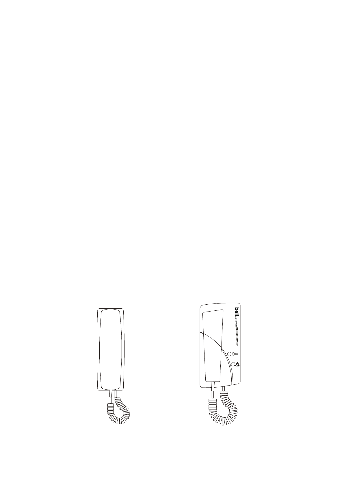
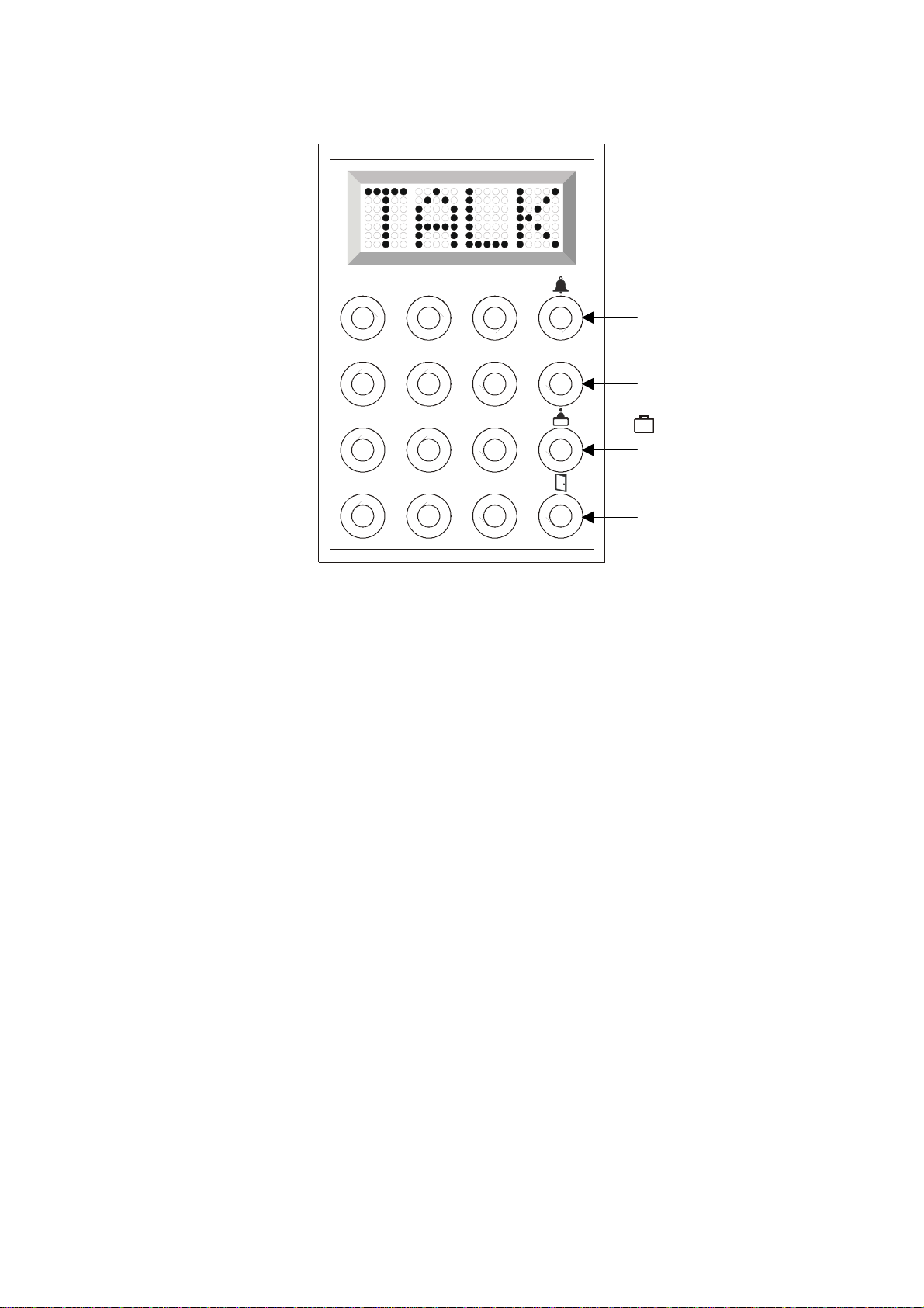
PHONE DETAILS .................................................................................................................5
BASIC SYSTEM OPERATION............................................................................................6
DESIGN CONSIDERATIONS..............................................................................................8
EQUIPMENT LIST.................................................................................................................8
POWER SUPPLY REQUIREMENTS .........................................................................................9
CABLE DISTANCES............................................................................................................11
INSTALLATION & COMMISSIONING ..............................................................................12
WIRING............................................................................................................................13
COMMISSIONING...............................................................................................................14
PROGRAMMING THE PHONES – BS-A OR BC801 NOT BC801-P OR BS-A-P........................15
PROGRAMMING THE PANEL – BCP1 ..................................................................................16
PROGRAMMING THE PANEL – BSD-DIG.............................................................................18
BSD-DIG DOOR CONTROLLER JUMPER SETTINGS .............................................................21
BS-A AND BC801 PHONE SWITCH SETTINGS.....................................................................22
BSC4-AD AUDIO ISOLATOR SETTINGS ..............................................................................23
TROUBLESHOOTING ......................................................................................................25
QUICK FAULT REFERENCE.................................................................................................25
SPECIFICATIONS.............................................................................................................29
DIAGRAM A – SYSTEM WIRING – BCP1 PANELS........................................................31
DIAGRAM B – SYSTEM WIRING – BCP/VR PANELS ....................................................32
DIAGRAM C – SYSTEM WIRING – BCP/VR PANELS ....................................................33
DIAGRAM D – SYSTEM WIRING – BCP/VR PANELS ....................................................34
DIAGRAM E – SYSTEM WIRING – BCP/VR PANELS ....................................................35
DIAGRAM F – SYSTEM WIRING – BCP/VR PANELS.....................................................36
DIAGRAM G – BCP1 DETAIL WIRING ............................................................................37
DIAGRAM H – BSD-DIG VR OR LCP PANEL DETAIL WIRING .....................................38
DIAGRAM I – PHONE DETAIL WIRING...........................................................................39
DIAGRAM J – BSC4-AD...................................................................................................40
DIAGRAM K – BSC4-AD DETAIL WIRING......................................................................41
DIAGRAM L – OPTION DETAILS.....................................................................................42
DIAGRAM M – BELLISSIMO COMBINED SYSTEM CONNECTIONS ............................43
DIAGRAM N – ACT INTERCONNECTIONS.....................................................................44
SAFETY INFORMATION AND DECLARATIONS ............................................................45

Bellcall Digital Door Entry System
PD-083 Issue 3A Installation and Operating Manual Page 4 of 46
Introduction
Description
Bellcall is a digitally signalled phone system with keypad style flat number entry.
A Bellcall door entry system consists of a door panel, positioned at the entrance of a
building, door entry phones, placed inside of the building for the convenience of the
occupants, a power supply and controller which are usually located inside an electrical
cupboard. The door panel comprises of a two-way speech unit, an LED display and
sixteen push buttons – which are used by a visitor to initiate a call. The phone, which rings
in response, allows a two-way conversation via a handset. The operator can selectively
allow visitors access to the building by pressing a button on the phone and so electrically
releasing the door.
The Bellcall digital door entry system is suitable for any building requiring to address more
phones than considered practical for a conventional pushbutton panel.
The Bellcall digital system is supplied with a dedicated door controller, for each entrance
(the standard unit includes this in the panel assembly). The basic system supports 1
phone per address and a number of extension phones, consideration must be given to
cabling and power supply’s for the extra ringing current. Multiple entrances can be
supported with the addition of one panel (and one door controller if vandal resistant) for
each entrance.
Main Features
12V d.c. operation
BCP1 surface or BCP1F flush mounted panel with integrated controller.
BCP1/xxx vandal resistant panel types with separate controller for security.
BS-A audio version of bellissimo videophone with ringer volume, ringer mute and
door left open indicator.
BC801 digital version of the popular 801 phone.
High quality full-duplex speech amplifier.
Inherent privacy of speech.
Coded access facility built in (single 4 digit code).
Facility for exit button.
Timed lock release, fail safe or fail secure and magnetic locks (maglock).
Reception (Porter) facility built in.
Simple parallel wired system with a 6 wire bus.
Simply add door controllers onto the bus for multiple entrances.
Systems with over 1000 phones possible.
Trades facility built in (requires external time clock).

Bellcall Digital Door Entry System
PD-083 Issue 3A Installation and Operating Manual Page 5 of 46
The standard BCP1 integrated version needs no other control equipment, just the required
number of entrance panels, phones and a power supply. (Extra doors may need extra
power supplies). The system works on a 6-wire bus (6 common wires) with only the
requirement to take care of power supply distribution on larger systems (see table later in
this document). The use of standard Cat5 or CW1308 phone cable makes cable
installation extremely economic.
The vandal resistant version of the panel uses a separate controller which normally needs
to be positioned within 50m of the panel. This has added security as opening the panel
gives no access to door lock circuitry.
Clear and concise display messages are presented to the visitor. Simple commissioning
with user-friendly display messages.
The Bellcall system is very flexible and can be as simple as the system detailed above to
larger systems with BSC4-AD group isolators and possibly BSSW gate switchers. It is
also feasible that other bellissimo BSD8 or BSD72 controllers may be used in mixed
systems to provide small blocks with 1 button per flat panels. See ‘Design Considerations’
for more detail.
N.B. The term “Flat” is used generically to mean Flat, House or Office etc.
Phone Details
The BC801 phone is identical in style to our popular model 801 phone but contains the
necessary electronics for connection onto the Bellcall digital bus. The phone is
manufactured in white and grey high-impact ABS plastic that imparts high durability and
compliments most wall furnishings. It incorporates a ‘lock release’ push-button discreetly
positioned on the base, and under the handset, to prevent inadvertent use. It has an
Electronic Ringing Tone.
The BS-A phone is styled like our bellissimo videophone for audio only digital systems.
The phone is manufactured in white and grey high-impact ABS plastic that imparts high
durability and compliments most wall furnishings. It incorporates both mute and lock
illuminated buttons. It has an Electronic Ringing Tone with rotary preset volume.
Diagram 1: BC801 Phone BS-A Phone

Bellcall Digital Door Entry System
PD-083 Issue 3A Installation and Operating Manual Page 6 of 46
Basic System Operation
Number and Letter Buttons
The numbers 0 to 9 are used to enter numbers. The letter button >A enters letters
beginning with A and each press advances through the alphabet, while the letter button <Z
does the reverse starting with Z. For example pressing >A three time will give C then
pressing <Z once will give B, or starting with pressing Z 5 times will give V and then
pressing >A twice will give X. To end the entering of a character is done by pressing a
number button or call.
The call button is used to call flats or end sequences, in effect OK.
The cancel button cancels the current entry leaving a blank display.
The reception or Porter (Suitcase) button calls a phone dedicated to that location.
The door or Trades button is used to gain direct access either directly or via a code.
Call sequence
When the callers address entered and the call button is pressed at the entrance panel it
causes the phone to ring and the red mute lamp to flash. The phone will continue to ring
for up to 30 seconds or until the resident responds by picking up the handset. The green
lock lamp will flash to highlight the lock button.
The call may be terminated by replacing the handset or more usually by pressing the lock
button to allow the visitor access through the entrance.
Phone Controls
Diagram 1 shows the BS-A phone and its controls.
The ringer volume setting is inside.
The use of the mute, and lock buttons are described below.
Porter
or
Reception Button
Call Button
Cancel Button
Door Button (Trades)
1
2
3
4
5
6
X
7
8
9
>A 0
<Z

Bellcall Digital Door Entry System
PD-083 Issue 3A Installation and Operating Manual Page 7 of 46
Call Mute – BS-A Only
The resident can mute the phones ringing sound when they do not wish to be disturbed.
Call mute is activated by pressing the mute button on the phone, which illuminates in red
as a reminder. Pressing the mute button a second time will disengage the mute function.
During installation it is possible to set a time limit for the mute function in various values
from 2 minutes up to 10 hours or indefinitely. When this time period has elapsed the mute
function will automatically disengage. (See ‘mute timer’, page 18).
The mute feature stops the audible ring, but the red mute light will still flash to indicate a
call and all other functions work normally. Ringer mute will continue for the preset time
even if a call is answered.
Door Status Indication – BS-A Only
The green lock lamp on the phone will illuminate to warn the resident that a door has been
left open following a call. This feature requires a door monitor contact to be fitted.
Call Privacy
Once a call has been made from an entrance panel only the phone(s) which is/are ringing
may answer the call. Once answered, if another phones handset is picked up, the phone
will not activate (including extensions of the active phone).
Extension Phones
Additional phones may be added to each ‘flat’. The number of extensions is limited only
by power supply and cabling considerations. All phones for that ‘flat’ will ring when called.
Once a phone is ‘picked-up’ the conversation will only be with that phone.
Lock Type and Operation
The door controller supports both fail-secure and fail-safe locks including magnetic locks of
up to 0.5A rating (1A BSD-DIG). The lock output is provided by a relay contact (transistor
on BSD-DIG) switching Lock -, which in the event of power failure does not drive.
On pressing the lock button the lock timer will start and the door will unlock. For Lock
Time settings see page 19.
Exit Button
An input is provided for an exit button, which can be installed on the inside of the door and
allow residents to exit freely. Momentary operation of this button will operate the lock
release for the programmed lock time.
Trades Facility – Timed
Use of a time clock in conjunction with the door button allows free or coded access during
the programmed time. Without the time clock coded access can be used or disabled.
DDA Functionality
The vandal resistant version of Bellcall has a range of options for entrance panels to help
meet the requirements of the Disability Discrimination Act (DDA), including Illuminated
Tactile buttons and reassurance tones to indicate phone ringing and door released.
Contact your sales representative for further details.
Multiple Entrances
The Bellcall system allows multiple entrances to be catered for by the addition of a door
controller and entrance panel for each entrance and additional power supplies.

Bellcall Digital Door Entry System
PD-083 Issue 3A Installation and Operating Manual Page 8 of 46
Design Considerations
Equipment List
A Bellcall digital audio systems can vary in content significantly, but comprise of the
following items: -
A number of phones, either the new BS-A phones or the older BC801
None or more BSC4-AD Audio controllers as required to break up the wiring into 4
smaller segments each.
Then for each door:- Either
BCP1(F) Integrated door panel and controller.
Or a door panel and controller.
BCP1/LCP Vandal resistant panel LCP option.
BCP1/VR(S) Vandal resistant panel standard VR option.
BSD-DIG Door controller.
61 speech unit.
And common items
Power supply, see below for alternatives.
203 Fail-secure lock release, alternate types available.
DDA panels (Contact sales for further information).
Equipment Options
At the simplest all the door controllers and phones can be connected on a single bus, and
this works for smaller systems. However there is a data limitation of 128 items (phones or
controllers) on a single bus, and a total cable length limitation of about 1000metres.
BSC4-AD audio controller. This controller performs group isolation and allows both of the
above limits to be overcome. Each controller can split the phones into 4 groups which are
isolated from each other. Installation and maintenance are also improved in that if a fault
develops in a group of common wired phones, the fault is already isolated to just those few
phones.
Full Isolation. This is achieved by using the above BSC4-AD controllers with just one flat
per output. When doing this it becomes more efficient to use the BSC4-AD’s ability to use
unprogrammed or programmed phones with the BSC4-AD decoding the address.
BSSW Gate switcher block isolator. This controller is used wherever 2 or more blocks of
phones share a common door or gate and independent operation of the blocks is required.

Bellcall Digital Door Entry System
PD-083 Issue 3A Installation and Operating Manual Page 9 of 46
That is in a fully common wired system only 1 door can make a call at a time, in a block
isolated system there can be a call in every block simultaneously.
BSD8 and BSD72. These one button per flat controllers can be used to ring phones with
addresses of 1 to 8 and 1 to 72 respectively and would normally be used for a small block
in conjunction with a BSSW which can translate phone addresses. The bellissimo
manuals for these controllers would be used to determine switch settings. Application
would normally be as a result of contacting the technical department.
Mixed Audio Video Systems. A Bellcall system can be connected to a bellissimo video
system where there are shared entrances, the BSSW would be the recommended method.
All wiring carrying video must be installed to the requirements of the relevant bellissimo
installation manuals, however the Bellcall wiring may be added to any convenient point.
Do not connect the video signal into the Bellcall wiring.
Power Supply Requirements
The system is powered by 12V power supplies only: -
PS4 12V 4A Standard Supply
340C 12V 1.5A Standard Supply
840 12V 4A Battery backed supply
640 12V 1A Battery backed supply
Exact power supply requirements depend upon many factors. The number of power
supplies included for a system may assume that all boxed controllers are installed in one
location and that there are no extensions. More equipment may be required for distributed
installations.

Bellcall Digital Door Entry System
PD-083 Issue 3A Installation and Operating Manual Page 10 of 46
Cable Specification.
DO NOT USE Alarm cable.
All system wiring must be carried out using either Cat5 signal or CW1308 telephone cable
and where necessary 1mm² (or greater) power cable as tabulated below. Cat5 cable is
strongly recommended as it has a better performance and may allow future upgrades with
less re-cabling.
Bell System will be unable to offer any warranty or support for systems installed
using incorrect cables.
Cat5 Cable Specification
Cat5 is our short reference for EIA standard UTP Category 5 Unshielded Twisted Pair data
cable. This is a standard 0.5mm diameter 0.2mm² solid core twisted pair cable having 4
pairs (8–cores) and no shield. The cores are in pairs where Blue and ‘Blue with a White
stripe’ are twisted together as the first pair. The other three pairs are similar with main
colours Orange, Green and Brown.
Also available and acceptable are:
UTP Category 5e (Cat5e)
UTP Category 6 (CAT6)
UTP Category 6e (CAT6e)
The exact cable can be chosen from the above on cost and availability grounds.
STP (Shielded Twisted Pair) cables are not recommended.
NOTE: Cat5 cable is easily identifiable as the specification is printed on the sheath.
UTP Patch cable is normally more expensive, but is otherwise suitable for audio and data
use.
CW1308 Cable Specification
CW1308 is the international standard for telephone cable which is available in sizes from 1
pair to in excess of 25 pair. The standard CW1308 has 0.5mm diameter 0.2mm² cores.
Different grades are available including a cheaper 0.4mm diameter 0.12mm² core and a
1.38mm diameter 1.5mm² core for long distance, though these are not normally available
through common outlets. All our calculations are based on the 0.5mm diameter cores
which are the same as Cat5 cores.
Cable Dimensions
Cable Types
0.5mm dia. = 0.2mm2Solid core twisted pair, Cat5 or BT Spec. CW1308
1.12mm dia = 1.0mm21.0mm2, e.g. ‘Twin & Earth’ or flexible cord

Bellcall Digital Door Entry System
PD-083 Issue 3A Installation and Operating Manual Page 11 of 46
Cable Distances
Volt drop along the 12V DC + and – power connections is the limiting factor. Where
needed these are increased to 1mm2. Please check the table below.
Phones may need either larger power cores or doubling up depending on the distance
involved. E.g. when using 4 pair cable (8 cores) instead of 3 pair cable (6 cores), the
distances would be double those indicated for 6 cores below.
Connections to the junction box - refer to diagram ?
Connection No. of
Cores Cable Length Core Size
Power Supply to junction box 2 2m 1mm2
TS2000 Time Clock 4 50m 0.5mm dia.
Phones per branch: 1 80m
2 70m
5 50m
10 30m
20
6 (3 pairs)
20m
0.5mm dia.
Phones per branch: 1 165m
2 140m
5 100m
10 65m
20
8
(4 power
+ 2 pairs) 40m
0.5mm dia.
5 150m
10 125m
20
2 + 4
(2 power
+ 2 pairs) 75m
2 @ 1mm2
+ 4 @
0.5mm dia.
BCP1 Entrance Panel Connections
Connection No. of Cores Cable Length Core Size
10m 0.5mm dia.
Junction Box (see diagram 1) 6 (2 + 2pairs) 40m 2 @ 1mm2+ 4
@ 0.5mm dia.
If using a TS2000 Time Clock 2 50m 0.5mm dia.
Exit Button (optional) 2 50m 0.5mm dia.
Lock Release (0.5A) 2 5m 0.5mm dia.
Panel to BSD-DIG Door Controller
Connection No. of Cores Cable Length Core Size
BCP1/LCP (16 VR
buttons + LED display) 18 50m 0.5mm dia.
BCP1/VR(S) (16 VR
buttons + LED display) 18 50m 0.5mm dia.
2 10m 0.5mm dia.
Lock Release (1A) 2 50m 1mm2
Option: Exit button 2 50m 0.5mm dia.
Option: Door Monitor Switch 2 50m 0.5mm dia.
Power supply to controller 2 3m 1mm2

Bellcall Digital Door Entry System
PD-083 Issue 3A Installation and Operating Manual Page 12 of 46
Installation & Commissioning
The following checklist is a reminder of what is required. Refer to the relevant pages for
further details.
●Review the section headed ‘Important Safety Information’ on page 45.
●Ensure that ‘Design Considerations’ on page 8 have been understood.
●Confirm that Cat5 cable (or CW1308) has been specified.
●Install the system according to instructions in this section.
●Check/set the audio controller BSC4-Ax switch settings.
●Check/set each phone dipswitch and or jumper settings.
●Check/set the door controller BCP1 or BSD-DIG settings.
●Program the phones/phones if required.

Bellcall Digital Door Entry System
PD-083 Issue 3A Installation and Operating Manual Page 13 of 46
Wiring
Refer to Diagrams A through E as appropriate for the equipment you have.
All wiring is carried out using a mixture of Cat5 or telephone cable for the signal wiring and
1mm² (or greater) cores for the power wiring; refer to Page 11 for further details. It is
strongly recommended that a consistent colour code be used throughout such as that
indicated on the connection diagram. Certain signals must be interconnected using a
twisted pair from the Cat5 cable. These are clearly marked on the connection diagram
and should be strictly observed.
Entrance Panel
The panel should be mounted at an optimum height of 1.6 m, measured between the
ground and top of panel. With flush mounting panels it is advisable to apply mastic to the
top and side edges of the panel to prevent water ingress behind the panel, but not the
bottom edge. On construction sites the panel must be protected from corrosive
substances such as ‘brick acid’. The panel should be cleaned only with a damp cloth
containing dilute detergent.
Phone
The phone is designed to be wall mounted onto plasterboard or other masonry, DDA
considerations may dictate a lower height. It should be fixed with No 6 screws (not
supplied). If the cable is to be feed from the wall cavity then make a hole for this at the
same time. The top cover of the BS-A phone is secured by clips at both sides. Before
replacing the Front Cover check that the DipSwitch settings are correct or change as
necessary (see Page 18).
Electric Door Release
Both fail-secure and fail-safe lock releases (including magnetic locks) use the same
terminals. To set the lock type, refer to the ‘Door Controller Settings’. When installing lock
releases please allow a little movement on the door, as operation will be impaired if fitted
too tight.
NB. Magnetic locks (maglocks) must be fitted with a suppressor at the lock terminals.
Some manufacturers fit an acceptable internal suppressor.
Fail Safe Exit Notes
Fail safe exits require an exit button and this should be normally open so that the controller
can be used to give a timed exit. If the exit button has both normally open and normally
closed contacts, then the normally closed contact can be wired in series with the release /
maglock along with the break glass in case of equipment failure.
A not uncommon problem with maglocks is being locked out of the building due to
equipment failure, lost codes or fobs. So consider an alternate building entrance, or an
externally accessible secure keyswitch, or a reliable method of disabling the system during
overnight secure lockup.
Fail Secure Exit Notes
Commonly fail secure exit doors incorporate a thumb-turn, door handle or mini push bar
rather than use of an exit button. Fire officers usually require a minimum of door handle or
push bar to open a door on a fire exit route – not thumb-turn.
Most fail safe locks are not continuously rated and if an electrical hold open system is used
for say busy times, then a continuously rated release must be used.

Bellcall Digital Door Entry System
PD-083 Issue 3A Installation and Operating Manual Page 14 of 46
Powered bolt, shoot-bolt or other more secure door locking systems may require the use
of separate power supplies or having suppressors fitted. Shoot-bolt systems for instance
tend to require at least 1.5A peak current and this will require the use of an isolation relay
and normally a separate power supply for the lock.
Exit Button Input
The exit button is used to unlock the door for the lock operating time. The input is only for
a normally open push button. ‘Exit +’ is the input and ‘Exit –’ is internally connected to 0V.
The input can also be used for connection to other equipment to open the door as shown
in the interconnection diagrams K and L.
Door Open Switch – BSD-DIG only
The door open switch is used to provide an indication at the phone that the door has been
left open. This switch can have closed contacts when the door is closed or open contacts
when the door is closed, the choice being made in Panel Programming. The default of
‘contacts open when door closed’ must be selected when this feature is not required.
Time Clock Sharing
In a large system the time clock can be shared between distributed entrances by using
one of the Cat5 common wires for the common time clock signal. Se the detailed diagram
on page 42.
Commissioning
The many components of the Bellcall Digital system are fitted with high quality pluggable
screw terminal blocks. This enables all the connections to the system to be fully
completed, whilst easily isolating individual pieces of equipment during testing and
commissioning.
When powering up for the first time, it is highly recommended that only the most basic
system be connected. i.e. 1 phone, 1 door controller and panel, the remaining equipment
can be isolated by removing terminal blocks at the video and door controllers.
Proceed to test the system by calling the phone from the door panel in the usual way. Any
problems can be resolved by rechecking wiring and connections, assisted by the various
suggestions and tests in the section “Troubleshooting”. Once the basic system is fully
functioning, continue to reconnect and test the remaining equipment item by item until
completed.

Bellcall Digital Door Entry System
PD-083 Issue 3A Installation and Operating Manual Page 15 of 46
Programming the Phones – BS-A or BC801 not BC801-P or BS-A-P
Each phone on a Bellcall system must be programmed with a unique 1-4 digit flat number,
including one or two alphabetic characters.
Valid numbers: 6, 23, 2001, A47, 103G, B1A, 1A1A, A1A1.
Adjacent alphabetic characters cannot be programmed: LG, 1AA, AA1, 1AB2, 21AA.
Alphabetic Characters are selected by first pressing A> or <Z, subsequent presses of A>
will step through the alphabet in a positive direction (A, B, C, …), whilst the <Z button will
step in a negative direction (Z, X, Y, …).
BC801-P phones are supplied pre-programmed.
Program procedure: (Two man operation)
1. Ensure phones to be programmed are on the hook.
2. Enter Phone Security Code at any panel (default 1212) followed by CALL.
3. Display says WAIT.
4. Pick-up Handset to be programmed ; Display says TALK. Panel and handset may
talk to each other; confirm phone new identity.
5. Type new number followed by CALL; Display says OK to confirm.
Program procedure: (One man operation)
Prepare a power supply controller and phone connection either in situ or at a convenient
location and follow the above procedure one phone at a time. Mark each phone with its
address and then install them.
Test procedure:
1. Instruct second man to hang-up phone.
2. Call phone from panel using new address e.g. 123 CALL
3. Second man awaits phone ringing then pick-ups to talk.
4. Second man Presses Lock button; first man confirms lock is released at panel.
5. Hang-up and repeat Program procedure for next phone.
It is strongly recommended that the Phone Security Code (TSEC) be changed from its
factory setting to prevent unauthorised access (see next page). Record the new number
carefully as it cannot be easily changed if lost.

Bellcall Digital Door Entry System
PD-083 Issue 3A Installation and Operating Manual Page 16 of 46
Programming the Panel – BCP1
The BCP1 is programmed from the panel for all settings.
Security
It is strongly recommended that the Panel Security Code (PSEC) be changed from its
factory setting to prevent unauthorised access. Record the new number carefully as it
cannot be easily changed if lost. It is also recommended that the Phone Programming
Code (PPRG), and Coded Access Code (ACOD) are all changed from default even if not
used.
To access panel programming without the code requires physical access to the controller.
Now pressing the test button will enter panel programming for 10S when the panel security
code can be read or set..
Panel Programming
To use Panel Programming Mode :-
firstly type the Panel Security Code (initially 3434) followed by the call button.
The display will show the first programmable parameter (MODE).
Press the door button to alternate between the current value of the parameter and the
name of the parameter.
Press the porter button to step through the programmable parameters:
To change a parameter simply type a new 4-digit value and then press call.
To exit Panel Program Mode press cancel.
If no button is pressed for 10S then programming mode will auto-cancel.
Code Action Default Action Description
MODE 5003 Multi-Function (See Below)
CODE 1234 Access Code
PORT 0101 Reception/Porter’s Phone Number
PSEC 3434 Panel Security Code
TSEC 1212 Phone Security Code – Program Phone

Bellcall Digital Door Entry System
PD-083 Issue 3A Installation and Operating Manual Page 17 of 46
MODE parameter
Enter a 4-digit number ABCD, Where:-
A is the Trade Mode 0-9 (see table).
B is the lock type; 0= fail secure, 1=fail-safe.
C is unused, set to 0.
D is the lock duration 0-9 secs.
Default 5003; Trade Mode 5, Fail-Secure Lock, Lock Duration 3 seconds
A Trade Mode:
Code = Pressing the door button prompts for the access code to open the door.
Door = Pressing the door button opens the door.
None = No function pressing the door button is ignored.
E.g. 5105; Trade Mode 5, Fail-Safe Lock, Lock Duration 5 seconds
Trade Mode SettingTime
Input 0123456 7 8 9
Open None Door Code None Door Code None Door Code None
Closed None None None Door Door Door Code Code Code None
CODE – Access Code
Code to open the door. Valid whenever the display indicates CODE. The Trades mode
needs to be set to Code as per the table above. The default is 1234 and it is
recommended that this is changed for security.
Letters cannot be used in this code, and 4 digits must be used, leading 0 is OK.
PORT – Porter Phone Address
The porter button is used to call a porter or reception desk or similar. The number is that
of the called phone. The default is 101 which is unlikely to be used by a flat.
PSEC – Panel Security Key
The security key is required to gain access to panel programming.
The code is entered then pressing the call button, the default is 3434 and it is
recommended that this be changed for security.
This code can contain letters and numbers for added security.
TSEC – Phone Programming Security Key
The phone programming security key is required to gain access to flat number
programming of telephones. The default is 1212 and it is recommended that this be
changed for security.
This code can contain letters and numbers for added security.

Bellcall Digital Door Entry System
PD-083 Issue 3A Installation and Operating Manual Page 18 of 46
Programming the Panel – BSD-DIG
The BSD-DIG is programmed from the panel for all settings.
Security
It is strongly recommended that the Panel Security Code (PSEC) be changed from its
factory setting to prevent unauthorised access. Record the new number carefully as it
cannot be easily changed if lost. It is also recommended that the Phone Programming
Code (PPRG), Coded Access Code (ACOD) and Trades Access Code (TCOD) are all
changed from default even if not used.
To access panel programming without the code requires physical access to the controller
PCB, borrow a jumper from say video gain (remember the setting) and place it on the 5 pin
programming header between pins 1 & 2. Now pressing the test button will enter panel
programming for 30S when the panel security code can be read or set. When the
programming is finished replace the jumper back to its original location.
Panel Programming
To use Panel Programming Mode :-
First type the Panel Security Code (initially 3434) followed by the call button.
The display will show the first programmable parameter (ACOD), and then alternating
at 1S intervals will be the data and the parameter name.
Press the door button to step down through the programmable parameters.
Press the reception button to step up through the programmable parameters.
The list rolls over bottom to top and vice versa.
To change a numeric parameter simply type a new 1-4-digit value and then press call.
To change other values simply press call to choose the next value.
To exit Panel Program Mode press cancel.
If no button is pressed for 30S then programming mode will auto-cancel.
Code Default Access Description
ACOD 1234 Coded access code – must be 4 digits
TCOD 6789 Trade access code – must be 4 digits
LTIM 0003 Lock Time: 1-99 seconds
LOCK Secr Lock Type: Secr (fail secure), Safe (fail safe)
CAM2 No Camera 2: No (absent), Yes (present)
TRAD 0005 Trade Function: 0-9 – see table
DMON Cwo Door Monitor Polarity: Cwo, Owo
RECP 9898 Reception / Porter phone number
PSEC 3434 Panel security code
PPRG 1212 Phone programming security code
RING 0015 Ring Time – see table
TALK 0015 Talk Time – see table
TONE Both Ring and Lock Buzz-Tone enable, 4 settings
CANC Yes Allow Cancel button to terminate Call
BCAL No Bellcall BCP1 compatibility mode
12A? No Allows user entry of 12A to call BSC4 output 13

Bellcall Digital Door Entry System
PD-083 Issue 3A Installation and Operating Manual Page 19 of 46
ACOD – Primary Access Code
Main code to open the door. Applies whenever the display indicates [Code]. The Trades
mode (TRAD) needs to be set to ‘Code’ or ‘Trade’ as per the table below.
The code must be 4 digits and no letters, leading 0 is OK (e.g. [0246]).
TCOD – Secondary Access Code or Tradesmen’s Code
Secondary ‘tradesmen’s’ code to open the door. Valid only when the display indicates
[Code] and the time clock selects the Trade option as per the table below.
The code must be 4 digits and no letters, leading 0 is OK (e.g. [0137]).
LTIM – Lock Release Operating Time
Door unlocked duration. Range 1 to 99 seconds. Only the last 2 displayed digits are
used. A value of 0 will default to 1 second and a value containing alpha characters will
default to 3 seconds.
LOCK – Lock Type
[Secr] = Fail secure lock: - Requires alternate mechanical means, key or thumb-turn
to open on power failure.
[Safe] = Fail safe lock: - Lock opens on power failure.
CAM2 – Second Camera Present?
[No] = Only 1 camera,
[Yes] = Second camera present.
TRAD – Door Button Trades Mode
‘None’ = No function; pressing the door button is ignored.
‘Door’ = Pressing the door button opens the door.
‘Code’ = Pressing the door button prompts for the [ACOD] access code to open the
door.
‘Trade’ = Pressing the door button prompts for either the [ACOD] or [TCOD] code to
open the door
DMON – Door Status Switch
[Owc] = Contacts open when door is closed: - The default allows for no switch fitted.
[Cwc] = Contacts closed when door is closed: - Standard normally closed switch.
RECP – Reception Phone Address
The reception button is used to call a reception desk or similar. The number is that of the
called phone. The default is [9898] which is unlikely to be used by a flat.
Setting [0] [1] [2] [3] [4] [5] [6] [7] [8] [9]
Time Clock OffNone None None None Code Code Code Trade TradeDoor
Time Clock OnNone Door Code Trade Trade Door Code Trade Door Door

Bellcall Digital Door Entry System
PD-083 Issue 3A Installation and Operating Manual Page 20 of 46
PSEC – Panel Security Key
The security key is required to gain access to panel programming.
The code is entered then pressing the call button, the default is [3434] and it is
recommended that this be changed for security.
This code can contain letters and numbers for added security.
PPRG – Phone Programming Security Key
The phone programming security key is required to gain access to flat number
programming of telephones. The default is [1212] and it is recommended that this be
changed for security.
This code can contain letters and numbers for added security.
RING – Ringing Time/Call Time and Ring Effect
Enter from 0 to 15 as per the table
Setting Ring Time Ring Cadence or Sound Effect
0 5s 1 in 3 – 1 ring every 3 seconds
1 8s 1 in 3 – 1 ring every 3 seconds
2 10s 1 in 3 – 1 ring every 3 seconds
3 15s 1 in 3 – 1 ring every 3 seconds
4 20s 1 in 3 – 1 ring every 3 seconds
5 30s 1 in 3 – 1 ring every 3 seconds
6 40s 1 in 3 – 1 ring every 3 seconds
7 45s 1 in 3 – 1 ring every 3 seconds
8 50s 1 in 3 – 1 ring every 3 seconds
9 60s 1 in 3 – 1 ring every 3 seconds
10 30s 1 in 3 (Reserved For future use)
11 30s 1 in 3 (Reserved For future use)
12 30s 2 in 15 – 2 rings, 15S silence, repeat
13 30s 1 in 15 – 1 ring, 15S silence, repeat
14 30s 1 in 5 – 1 ring every 5 seconds
15 30s* 1 in 3* – 1 ring every 3 seconds
Default setting
TALK – Talking Time/Phone Active
Enter from 0 to 15 as per the table
Setting Talk Time Setting Talk Time Setting Talk Time Setting Talk Time
0 15s 4 60s 8 150s 12 60s
1 20s 5 75s 9 180s 13 60s
2 30s 6 90s 10 60s 14 60s
3 45s 7 120s 11 60s 15 60s*
Table of contents
Other Bell System Telephone manuals

Bell System
Bell System 630A Assembly instructions

Bell System
Bell System 500LM/MM Assembly instructions

Bell System
Bell System 2636CA Assembly instructions

Bell System
Bell System 500A Service manual

Bell System
Bell System 701B User manual

Bell System
Bell System 5100AM User manual

Bell System
Bell System 220A Instruction Manual