manuals.online logo
Brands
  1. Home
  2. •
  3. Brands
  4. •
  5. Bell System
  6. •
  7. Telephone
  8. •
  9. Bell System 701B User manual

Bell System 701B User manual

BELLSYSTEM PRACTICES SECTION C38.670.00
Station Operations Manual Issue 1,October, 1960
Station Sets AT&TCo Standard
TELEPHONESETS
701 AND 711 TYPES
IDENTIFICATIONAND ASSEMBLY OF PARTS
1.00 INTRODUCTION 2.02 The 701B telephone set (Fig.1)is fur-
nished wired for individual and 2-party
This section covers the 701B, 701D, and flat-rate service. Changes may be made for other
711B telephone sets (see Fig. 1 through 9). These services as follows:
telephone sets are referred to as Princess sets. •Tip-party,message rate, flat rate with
automatic ticketing, zone registration,and
2.00 GENERAL automatic message accounting (a cord con-
ductor is moved to a different terminal as
2.01 These common battery desk-type telephone shown in the section on connections. When
sets are equipped with a lamp to illuminate no ringer is used, a coil for tip-party
the dial when the handset is removed. In addition, identification is installed in the base of the
this lamp acts as a night light under the control of telephone set. The 1610A inductor is
a switch. The 701B telephone set may be rewired expected to be available about October,
for use with 1A1 key telephone systems with 1960.
Alead control. This requires wiring changes
within the set.
Fig. 1- 701B Telephone Set
OAmerican Telephone and Telegraph Company, 1960
Printed in U.S.A.Page I
SECTION C38.670.00
Fig. 2-701D Message-Waiting Telephone Set
•4-party selective and 8-party semi-selective 2.04 The 711B telephoneset(Fig. 3)is fur-
service require a cold cathode tube. (See nished wired for 2oline pickup,exclusion,
Table A.) and signaling service. Wiring changesare made to
provide additional services as shown below:
• Use with 1A home interphone.
2.03 The 701D telephone set (Fig. 2) is the same
in design and circuitry as the 701B with the • Use with 2A farm interphone.
added feature of a message-waiting lamp. This set • Use with speakerphone systems.
is intended for use in hotels and motels which are
provided with the associated message-waiting See C section pertaining to the respective system
equipment, for specific changes required.
_E 4 IN.
LINE SWITCH JPUSH BUTTON
SWITCH
e i/2 iN.
Fig. 3- 711B Telephone Set
Page 2
ISS 1, SECTION C38.670.00
2.05 The 700-type telephone sets are available 3.00 DESCRIPTION
in the following colors" 3.01 Components of the 700-type telephone sets
White (--58) Aqua blue (--62) are shown in Table A and Fig. 4 through 9.
Rose pink (--59) Turquoise (--64) Descriptions of these items may be found in the
Light beige (--60) appropriate C sections.
SWITCHHOOK PLUNGER
HOUSING P-81M200 HAND GRIP
6-CONDUCTOR \FINGER STOP
MOUNTING CORD -';(_(GOLD FINISH)
495A NETWORK
DIAL LAMP RUBBER BASE PAD GOLD FINISH
Fig. 4- 701B Telephone Set with Housing Removed
Page 3
SECTION C38.670.00
TABLE A
COMPONENTS AND ASSOCIATED APPARATUS FOR 700-TYPE TELEPHONESETS
Type Dial Hand Mounting Network Dial Light Message Identifica- Tube for
Polarized
Set Set Cord Lamp Socket Waiting Lamp tion Coil Ringing
701B D6AB 1610A
Inductor 425A or 426A
701D 8A G3AR D6AB 495A GE _46 P-11E410 KS-16893, L1
711B D14H
3.02 The transmission circuit for the 700-type 3.04 The fingerwheel of the 8A dial requires
telephone set is the same as for the 500-type the use of the modified station number card
telephone set. However, since the ringer is always as covered in the C Section entitled Station Num-
external with a 700-type telephone set, there is no ber Cards and Holders.
ringing capacitor in the network.
3.05Aslide switch located inthe base of theset,
3.03 The 8-type dialused in the 700-type set has at the rear, controls the night-light circuit
a translucent number plate which is indi- (see Fig. 8 and 9). This circuit provides a steady,
rectly lighted by the dial lamp (see Fig.4 and 7). reduced illumination of the dial.
This lamp operates when the handset is removed
or the night-light switch is operated. Current for
the dial lamp is furnished by a 2012A or KS-16184
transformer.
1610A INDUCTOR--_
1610A
INDUCTOR -7
WEDGE-
/
BASE BASE
'WEDGE LIP UNDER TERMINAL STRIP;; .,:_;_._,.
,;,,¢,.
Fig. 5--1610A Inductor Showing Components Fig. 6-1610A Inductor installed in
701B Telephone Set
Page 4
ISS 1, SECTION C38.670.00
!
-. 03,
_,":HANDSET _'=_ "
_:_ P- 81K300 "_SWlTCHHOOK
EXCLUSION PLUNGER
PLUNGER
14-
CONDUCTOR
MOUNTING CORD HAND GRIP
._..-- 8A DIAL 5A
WORK
O.
/'T_V
'_,'_RUBBER
" .... _ BASE PAD
_w, ,oo_o_,_,s.,
Fig. 7-711B Telephone Set with Housing Removed
3.06 The lamp socket assembly, with the lamp, is easily removed through
the base of the set. It is not necessary to open the set for lamp
replacement. (See Fig. 8 and 9.)
Page 5
SECTION C38.670.00
LIGHT GUIDE :;
OFF-NORMAL CONTACTS
PULSING CONTACTS
I I
m !.... I
I_I
I.I
OPERATING _ I
SWITCHHOOKi
ARM SWlTCHHOOK CONTACTS SWITCHHOOK OPERATING
NIGHT-LIGHT
SWITCHON REAR
HOUSING
SCREW
|
I
I
.,,--- LAMPPILOT MINIATURE
SCREWBASE 6.8 VOLTS
0.25 AMP G.E. NO. 46
.q-.--LAMP SOCKET
ASSEMBLY P-IIE410
SLOT
Fig. 8-701B Telephone Set with Dial and Lamp Socket Removed
Page 6
ISS 1, SECTION C38.670.00
OFF-NORMAL CONTACTS
_u_o_o_,__i__.___ .,,c_oo_
SWITCHHOOK OPERATING IGHT-LIGHT
ARM ISWITCH ON REAR
TERMINAL ,_ .............. .... II lJ .. _
STRI P _ _ ......... ....
_ PUSH BUTTON "
___.SWITCH
LINE SWITCH
LAMP PILOT MINATURE
SCREW BASE 6.8VOLTS
0.25 AMP G.E.NO.46
__q_- LAMP SOCKET
;L_ ASSEMBLY P-lIE410
_SLOT
Fig. 9-711B Telephone Set with Dial and Socket Removed
Page 7
7 Pages

This manual suits for next models

2

Other Bell System Telephone manuals

Bell System 630A Assembly instructions

Bell System

Bell System 630A Assembly instructions

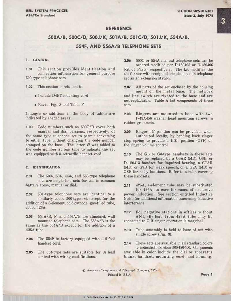
Bell System 500A Service manual

Bell System

Bell System 500A Service manual

Bell System 2636CA Assembly instructions

Bell System

Bell System 2636CA Assembly instructions

Bell System 500LM/MM Assembly instructions

Bell System

Bell System 500LM/MM Assembly instructions

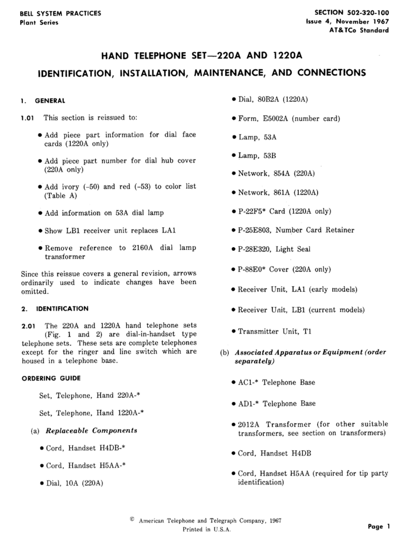
Bell System 220A Instruction Manual

Bell System

Bell System 220A Instruction Manual

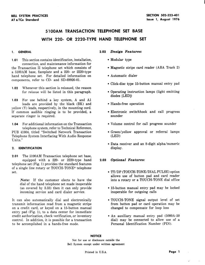
Bell System 5100AM User manual

Bell System

Bell System 5100AM User manual

Bell System Bellcall User manual

Bell System

Bell System Bellcall User manual

Popular Telephone manuals by other brands

Panasonic KX-TGP600 user guide

Panasonic

Panasonic KX-TGP600 user guide

Bosch Integral TH13 operating instructions

Bosch

Bosch Integral TH13 operating instructions

Digitmat Technology GP1266 user guide

Digitmat Technology

Digitmat Technology GP1266 user guide

Platon Yealink T30P instructions

Platon

Platon Yealink T30P instructions

ClearSounds CSC40 Installation guide & user manual

ClearSounds

ClearSounds CSC40 Installation guide & user manual

Nokia 6150 Service & Repair Hints

Nokia

Nokia 6150 Service & Repair Hints

British Telecom INPHONE Sceptre 120 Operating instructions & user guide

British Telecom

British Telecom INPHONE Sceptre 120 Operating instructions & user guide

Jabra CRUISER datasheet

Jabra

Jabra CRUISER datasheet

DAC Limited 711 Series user guide

DAC Limited

DAC Limited 711 Series user guide

Lucent Technologies 6225 quick reference

Lucent Technologies

Lucent Technologies 6225 quick reference

Barco Encore quick start guide

Barco

Barco Encore quick start guide

Phone Labs Cell Phone user guide

Phone Labs

Phone Labs Cell Phone user guide

LG LG-D405n user guide

LG

LG LG-D405n user guide

BT Featureline user guide

BT

BT Featureline user guide

Gigaset Gigaset DA410 overview

Gigaset

Gigaset Gigaset DA410 overview

Radio Shack ET-893 owner's manual

Radio Shack

Radio Shack ET-893 owner's manual

Polycom VVX 600 series Long format guide

Polycom

Polycom VVX 600 series Long format guide

Htek UC912G Configuration guide

Htek

Htek UC912G Configuration guide

manuals.online logo
manuals.online logoBrands
  • About & Mission
  • Contact us
  • Privacy Policy
  • Terms and Conditions

Copyright 2025 Manuals.Online. All Rights Reserved.